Note: Descriptions are shown in the official language in which they were submitted.
CA 02217727 1997-10-08
W 096/32020 PCTnUS96104166
APPARATUS AND METHOD FOR TREATING FLUENT MATERIAL
BACKGROUND OF THE INV~NTION
,.
Field of the Invention
The present invention relates to an
apparatus and method for sterilizing fluent
materials while m;n;m;zing alteration of the natural
flavor of the material and increasing the stability
of these materials. The present invention is
specifically directed to processing of a fluent
product and, more specifically, milk and to a method
where a major portion of the sterilizing medium is
derived from the fluent product by evaporation, is
condensed, reheated in a closed loop system and then
reintroduced into a sterilizing chamber thereby
isolating the fluent product from a source of
possible cont~;n~tion
Backqround of the Invention
A number of processes and apparatus have
been developed in recent years for the purpose of
heat treating fluent material, such as a dairy
product, to improve the shelf life of the product
without adversely affecting the organoleptic
properties of the food product or its nutritional
value. Included in the parameters of primary
concern to early workers in this field were the
maintenance of aseptic conditions while guaranteeing
the thoroughness of the sterilization process as
well as control of the flow parameters so as to
assure the effectiveness of the sterilization. For
certain fluent food products such as milk, careful
CA 02217727 1997-10-08
W096/32020 PCT~S~6/04166
hAn~ling of the product throughout the processing is
~ n~tory not only for health reasons but also for
the preservation of the desirable taste and other
organoleptic properties of the fluent food product.
As a consequence, the expense of sterilization has
been a prominent factor in the marketability of the
treated product.
Representative of the prior art in this
regard are U.S. Patents Nos. 4,310,476, Reissue
32,695 and 4,591,463.
While the prior art has succeeded in
providing effective and safe sterilization of the
fluent food and other products discussed in the
foregoing prior art patents, it has been difficult
to maintain the cost of the product to the consumer
on a level competitive with non-sterilized products
of a comparable type. Also, the process of
sterilizing with a medium foreign to the type of
fluent product has created the misapprehension on
the part of some consumers that the product could be
adulterated by the sterilizing medium. This has been
particularly true where the food product is milk
~ since, as noted in the references, this product has
shown significant sensitivity to sterilizing
techniques as well as sensitivity in the market
place to price variations of even a small amount.
Accordingly, it has been apparent that improvements
would be required in the manufacturing process and
apparatus in order to enable a producer to place on
the market a sterilized fluent product such as milk
which is safe, of high, consistent quality and at a
competitive price. It is to this end that the
present invention is directed.
SUMMARY OF THE INVENTION
CA 02217727 1997-10-08
PCTnUS96/04166
W 096/32020
According to the present invention,
several modifications of the basic sterilizing
process and apparatus such as disclosed in United
States Patent 4,310,476, the disclosure of which is
incorporated herein by reference, have been made
which either singly or in combination will
appreciably reduce the production costs while
preserving or enhancing the integrity of the fluent
food product. These benefits come as a result of
increased precision in the control of the flow of
the product through the system while reducing the
energy consumed to effect the transport and
sterilization steps of the process. In a preferred
form, a closed loop system will be employed to
manage the sterilization medium thereby preserving a
substantial portion of the energy used to raise the
medium to the sterilizing temperature as well as to
isolate the product from any possible cont~m;n~tion
from external sources. Also, savings in terms of
product costs are effected by the use of a specific
type of heat exchanger to condition the fluent food
product prior to and subse~uent to the sterilization
step. Additionally, by appropriate extraction of
non-condensable gases from the sterilizing chamber,
it has been found that the heat transfer efficiency
of the process can be remarkably increased.
The foregoing and other advantages will
become apparent as consideration is given to the
following detailed description taken in conjunction
with the accompanying drawings, in which:
BRIEF DESCRIPTION OF THE DRAWINGS
Figures lA, lB and lC are schematic
illustrations in flow chart form of the process of
the present invention;
CA 022l7727 l997-l0-08
PCTnUS96/04166
W O 96/32020
Figure 2 is an enlarged view, partly in
section, of the sterilizing chamber of the present
invention;
Figure 3 is an enlarged detailed view of
the circled portion of Figure 2;
Figure 4 is an enlarged view of a flow
control device of the present invention; and
Figure 5 is an enlarged detailed view of
the steam generator of the present invention.
DETAILED DESCRIPTION OF THE INVENTION
Turning now to the drawings wherein like
numerals designate corresponding parts throughout
the several views, there is shown in Figures lA, lB
and lC a schematic, flow chart view of the process
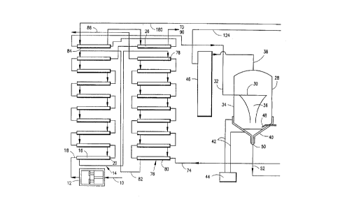
and apparatus of the present invention. Referring,
in particular, to Figure lA, there is shown an inlet
conduit 10 which is connected upstream to a source
of supply for the fluent product which may be a
liquid food or other type of fluent material
re~uiring sterilization. Conduit 10 is connected to
a pump 12 which preferably is of the multiple
piston, high pressure type rather than the turbine
or blade type since a piston type pump has been
shown to be more efficient in moving without
slippage a fluent food product through a system such
as is used in the present invention and will also
provide better control of the velocity of the fluent
food product in the system while minimizing damage
to the product. The piston pump 12 shown is of the
type having a chamber in which the piston
reciprocates and which carries one or more flow
passages closed on one side by one way valve
members. Other types of piston pumps may be used.
It will be understood that the process of this
CA 02217727 1997-10-08
PCT/U~/0~166
W 096/32020
invention may be used with a wide variety of
different fluent food products with little or no
modification of the apparatus and in the following,
milk will be referred to as the fluent food product
by way of example.
From pump 12, the milk is fed to a bank of
heat exchangers 14. According to the present
invention, the heat exchanger bank 14 comprises a
plurality of connected heat exchanger elements such
as at 16. Each element 16 will preferably comprise
central multi-tubular passageways for the milk food
product entering at one end 18 and exiting the tubes
at the opposite end 20. Along the tubes and
surrounding the tubes is a chamber through which
heated liquid such as hot water is passed from a
downstream set of heat exchangers as described
below. With this arrangement, the heating medium is
continuously recirculated through the system to
conserve energy and a gradual step up in temperature
of the fluent food product will be achieved until
the final heat exchange elements 26 and 84 are
traversed by the food product before being
introduced to the sterilizing chamber 28.
As has been disclosed in the earlier
patents of the assignee and particularly U.S. Patent
4,591,463, the sterilizing chamber will include one
or more film-forming heads 30 which will receive the
fluent food product from a conduit 32 which in a
sealed manner passes through the wall 34 of the
sterilizing chamber 18.
As has also been explained in the above-
noted patents, the head 30 will deliver the fluent
food product in a thin film by gravity flow from the
distributing head generally in a free-falling film
36 which has proven to be particularly effective in
terms of the interaction of the fluent food product,
CA 02217727 1997-10-08
W 096/32020 PCT/U~5~10~166
such as milk, with sterilizing steam which is
introduced from a conduit 38, as discussed below.
In this embodiment, the lower conical portion of the
sterilizing chamber 28 is provided with a cooling
jacket 40 which may be supplied with circulating
cooling medium such as water, vegetable oil or air
through conduits 42 supplied from a source 44.
The conduit 38 delivers sterile steam from
a steam generator 46 which will be described in more
detail below.
As explained in U.S. Patents 4,310,476 and
4,591,463, it is important to the preservation of
the organoleptic properties of milk as well as other
fluent food products that the exposure to heat be
maintained in as short a possible interval
consistent with the desired level of sterilization
which is defined generally in terms of reduction in
active bacteria level. Baffle means as disclosed in
the above noted patents may be mounted within said
pressure vessel for reducing the flow velocity of
the heated gas within said vessel to achieve rapid
heating of the film of fluent material while
subjecting the film to minimum physical
perturbation. In the present invention, it has been
discovered that the heat transfer efficiency between
the fluent food product such as milk and steam can
be significantly increased by the removal of inert
gases particularly those that are non-condensable
and which are generated in the sterilizing chamber
from the steam source but which may also be
generated as the milk is heated. To counteract
this, the present invention provides a vent 48
through the lower half of the sterilizing chamber 28
as shown in Figure lA and in more detail in Figure
2. This will be in addition to the vent located in
the upper portion of the chamber. It is estimated
CA 02217727 1997-10-08
PCTrUS96/04166
W O 96132020
that the increase in hëat transfer efficiency will
be on the order of 50% upon the removal of the non-
condensable gases in the lower portion of the
chamber 28 thus significantly reducing the time and
the steam pressure the milk need be exposed to in
the ~h~ h~ 28.
The bottom of the chamber 28 is provided
with an outlet 50 connected to a conduit 52 through
which the now heated liquid food product is fed, as
shown in Figure lB, through a holding tube as
indicated at 54 for the purpose of retaining the
milk product in the conduit 52 for a specified and
controllable period. By insulating the conduit 52,
heat will be retained in the fluent food product
during its passage through the section 54 until the
conduit 52 terminates at a flow control device 56
which is preferably of the variable orifice type 58
which operates in stepped transitions and may be
followed by a fixed orifice flow control device 56
which is located immediately upstream of a vacuum
chamber 60. The purpose of the variable orifice
control device 58 is described in prior U.S.Patent
4,591,463 and which will be summarized below. The
opening of the orifice 58 is selected to provide the
dwell time necessary to complete sterilization to
the desired level in the conduit 52 upstream of the
variable orifice flow control device 58. In some
circumstances, the fixed orifice 56 may be
eliminated which is desirable since it has been the
practice to provide cooling water to this orifice to
maintain its constant cross sectional flow area.
With a variable orifice flow control device 58 which
is shown in more detail in Figure ~, as discussed
below, this necessity is eliminated.
Downstream of the device 58 is the vacuum
chamber 60 which is maintained at approximately 250
CA 02217727 1997-10-08
W O 96/32020 PCTrUS96/04166
millibar absolute. As a re~ult, any water taken up
by the fluent food product, such as milk, will flash
to steam upon exposure to the vacuum in the chamber
60. This will also have the effect of rapidly
cooling the fluent food product. Under these
conditions, the steam will be drawn off through a
collector 62 located adjacent to the top 64 of the
chamber 60 while the fluent product will collect in
the bottom neck portion 66 of the chamber 60. A
cooling jacket 68 is preferably provided about the
bottom neck portion 66 of the chamber 60 to prevent
reboiling of the fluid. Water will be supplied to
the jacket 68 by conduits 70 from a supply 72. Fr~m
the portion 66, a conduit 74 is provided to connect
the fluent product to a piston type homogenizing
pump (not shown) which will deliver the fluent
product to a bank of heat exchange tubes 76 which
are preferably also of the tubular form. The heat
exchange fluid may be process, i.e. non sterile,
water from a suitable source which is delivered to
the topmost tube 78 of the bank 76. The lowermost
tube 80 has the heat exchange fluid such as water
delivered by a conduit 82 to the uppermost heat
exchange tube 84 of the heat exchange bank 14. With
this arrangement, the residual heat in the fluent
food product will be used to warm the incoming fresh
fluent product from line 10 in a gradual, stepwise
manner and makes use of the recirculation of the
heating medium acheiving, as will be apparent, a
useful energy s~aving in the arrangement of the dual
heat exchange banks 14 and 76 as described above.
From the uppermost heat exchange tube 78,
the cooled fluent food product is fed by conduit 86
to an aseptic storage or directly to packaging
equipment.
With reference now to Figure lC, there is
CA 022l7727 l997-l0-08
W 096/32020 PCT/U~ 1166
shown an arrangement of heat ~h~n~e elements 88,
90 and 92. Element 88 is used to recapture the
clll in~y steam used to sterilize the ~ood product
and is fed by con~--;t 62 from the vacuum çhA~er 60.
The steam is cQn~ in heat ~Y~h~e element 88
which is cooled by process water ~rom source 102.
Passage of the cooling fluid will be vertically
upwardly from the inlet 105 to the outlet 106
adjacent the upper portion of heat ~Yc-h~nger 88
where the now warmed cooling fluid is returned by
c~ll;t 108 to the supply 102. The condensed steam
is fed as water back through conduit 124 and a
filter 125 to the steam generator 46. Heat exchange
elements 90 and 92 are used to capture the non-
condensable gases which are removed from the lowerend of heat exchange element 88. The cooled gases
are drawn off from the element 88 through tube 98
and delivered to the inlet end of heat exchange
element 90. The now cooled gas stream is passed
through the tube 98 to a Venturi pressure
recompressor 110 which is fed through conduit 112
with saturated steam from a source 118 and this will
have the effect of drawing off the gases from the
heat exchanger 88 and facilitate passage through
conduit 114 to the inlet of the second heat exchange
element 9o. The subsequent heat exchanger 92 is
similarly equipped with an upstream located Venturi
pressure recompressor 116 fed from the saturated
steam source 118. A separate water supply 120 may
be employed as the cooling ~luid in the downstream
heat exchangers 9o and 92. The cooled non-
condensable gases are removed at 123 for optional
use in other processes The heat in the steam
extracted from the heat exchange elements 90 and 92
is passed through conduit 180 to heat exchanger 26
thereby effecting a 10 to 15% energy saving in the
CA 02217727 1997-10-08
W 096/32020 PCT~US96/04166
operation of the system.
once the system is charged, the
sterilizing heating medium, culinary steam, is
utilized in a closed loop without cont~ in~tion from
any external source except by contact with the food
product in the sterilizing chamber 28. Moreover,
water naturally present in some fluent food products
such as milk will provide a quantity of the liquid
to generate steam in the vacuum chamber 60 and which
will be reintroduced into the food product in the
sterilizing chamber 28. As a consequence, the cost
of purifying the liquid introduced into the steam
generator 46 is significantly reduced while the
sterile handling of the food product is greatly
facilitated. Any make-up water that is required as
a result of heat losses to the atmosphere and due to
removal of non-condensable gases can be supplied
from a potable source 125 which intercepts line 124
at a convenient junction upstream of the steam
generator 46.
With reference to Figure 2, there is shown
in enlarged detail view, partly in section, the
sterilization chamber 28 which has the exterior
coated with an insulating jacket 126 and the non-
condensable gas vent tube 48 installed in the lowerconical portion of the chamber 28.
The free-falling film distributor head 30
is constructed preferably as in U.S. Patent
4,419,301 although other constructions may be
employed so long as a thin, free-falling film is
achieved in operation.
In Figure 4, there is shown a detailed
view of the variable orifice flow control device 58.
This is preferably of a type that is commercially
available and includes a L path 128 having an inlet
130 and an outlet 132 and a seat 134 against which
CA 02217727 1997-10-08
W O 96132020 PCTrUS96/04166
is movable a closùre plug 136 which is preferably of
the type having a sealing member 138 provided about
its periphery to engage the seat 134 in a sealing
manner. The plug 136 is mounted on a movable piston
140 which may be actuated by a pressure actuator 152
to move toward and away from the seat 128. In the
illustrated embodiment, the signal arm 144 is
connected by a pin 146 to a collar 148 slidably
mounted on a rod 150. Movement of the arm 144
transverse to the axis of the rod 150 will send a
signal to the control box 142 which reports to the
pressure actuator 152 to effect control of the
opening and closing of the passage through the L
path 128. This arrangement which is commercially
available will compensate for air pressure
variations and other process variations by comparing
a detected value to intended positions. If not in
agreement, the control box actuates the pressure
actuator 152 to compensate. With this arrangement,
movement of the collar 148 will effect the
corresponding movement of the plug 136 to adjust the
size of the opening about the plug 136 and, as a
consequence, the flow through the device 58 to the
vacuum chamber 60. The control device 58 may be
connected to the pressure sensors 152 for the vacuum
chamber 60 to correlate the size of the opening
through the device 58 to the vacuum chamber 60.
In Figure 5, there is shown schematically
the steam generator 46 which is in the form of a
pressure vessel which includes an inlet 156 which
feeds an annular chamber 158. A second annular
chamber 160 includes a plurality of closely spaced
tubes, some of which are indicated at 162. Each
tube has an upper end in communication with chamber
158 and a lower end in communication with a chamber
or plenum 164. Chamber 160 is fed with a heat
CA 022l7727 l997-l0-08
W 096/32020 PCTnUS96/04166
exchange medium through inlet 166 in the illustrated
embodiment. This may be hot oil or high pressure
steam. With this operation, the liquid from heat
exchanger 88 which is usually at a somewhat elevated
temperature of approximately 65~C is introduced
through the inlet 156 and passes from chamber lS8
down through tubes 162 where the liquid is heated
and evaporated by the heat exchange medium 166. Due
to liquid recirculation, much of the liquid
introduced through the inlet 156 will enter the
plenum 164 as liquid. Another source of water for
the plenum may also or in the alternative be
provided. With this arrangement, the steam that is
generated as a result of heat exchange relationshi~
through the walls of the tubes 162 with the medium
166 will always be saturated steam which rises
through the central vertically extending chamber 168
to chamber 170 where the steam is passed through an
outlet 172 to conduit 38 and then to the sterilizer
28. While the heat exchange medium introduced at
166 may be steam or a hot fluid, other means for
heating the fluent material introduced through 156
may be employed including a gas fire, electrical
current or the like. It will be apparent, however,
that the medium entering through inlet 156 is kept
separated from the medium introduced through inlet
166 so that the integrity of the culinary steam will
be preserved.
Having desribed a preferred embodiment, it
will be apparent that various modifications may be
made thereto without departing from the scope of the
invention as described in the appended claims.