Note: Descriptions are shown in the official language in which they were submitted.
CA 02217735 1997-10-08
WO 97/30940 PCT/ITS97/02393
WATER SOFTENING SYSTEM WITH
SELF AD.1USTING RINSE CYCLE
FIELD OF THE INVENTION
S The present invention concerns a novel water softening system
and, more particularly, a system for determining when the rinse cycle of the
regeneration of a water softener has been completed.
BACKGROUND OF THE INVENTION
In Rak et al. U.S. Patent No. 4,299,698, issued November 10,
1981, an apparatus is disclosed for regenerating the ion exchange bed of a
water softener. The apparatus includes an electronic control circuit using a
probe carrying two pairs of spaced electrodes which are connected in a bridge
circuit. The upper pair of electrodes comprise a sensor cell and the bottom
1S pair of electrodes comprise a reference cell. A control signal and a
reference
signal are obtained from the sensing cell and reference cell for closing an
energizing circuit and latching it until it is time for regeneration, which
will
occur at preset times to avoid interfering with normal water usage.
Although Rak et aI. U.S. Patent No. 4,299,698 discloses a circuit
for determining when regeneration is necessary, I have discovered a system in
which a spaced reference cell and a spaced sensing cell can be utilized to
determine whether the rinse cycle of the regeneration has been completed or
is abnormal. I have discovered that the impedance difference of the solution
in the water tank between the reference cell and the sensing cell goes through
2S three stages during the slow rinse portion of regeneration. At the
beginning
of stage one of the slow rinse, the entire bed is in a sodium ion rich state
immediately after the brine draw. During stage two of the slow rinse, raw
water enters the top of the tank and the excess sodium brine is drawn out of
the drain tube at the bottom. A high sodium ion -- low sodium ion front
CA 02217735 2004-03-26
forms and gradually advances down through the tank as it reduces the sodium
ion
concentration. The third stage occurs when the sodium ion concentration is
uniformly reduced
in the zone between the sensing cell and the reference cell. I have discovered
that the slow
rinse is not complete or is abnormal if these three stages do not occur.
Accordingly, the invention seeks to provide a system utilizing my discovery
of the three stages and determining whether the slow rinse cycle of a
regeneration on a water
softener has been completed or is abnormal.
Other aspects and advantages of the present invention will become apparent as
the description proceeds.
SUMMARY OF THE INVENTION
In accordance with the present invention, a water softening method is provided
which comprises the steps of providing a reference cell in a water tank and a
spaced sensing
cell in the water tank. The impedance difference of the solution in the water
tank between
the reference cell and the sensor cell is sensed. If the impedance difference
is a first state,
then after a predetermined period of time a determination is made if the
impedance difference
is a second state. If the impedance difference is a second state, then after a
predetermined
period of time a determination is made if the impedance difference is a third
state. If the
impedance difference is a third state, then after a predetermined period of
time the rinse cycle
is completed.
In the illustrative embodiment of the invention, the first state is when the
sensor
cell impedance is less than or equal to the reference cell impedance. The
second state is when
the sensor cell impedance is greater than the reference cell impedance, and
the third state is
when the sensor cell impedance is less than or equal to the reference cell
impedance.
In the illustrative embodiment of the invention, a bridge is provided
with the reference and sensor cells as branches of the bridge. The
2
CA 02217735 1997-10-08
WO 97/30940 PCT/US97/02393
first state is when the bridge is balanced; the second state is when the
bridge
is unbalanced; and the third state is when the bridge is balanced.
In accordance with one embodiment of the present invention,
a water softening apparatus is provided. The water softening apparatus
comprises a water tank, a brine tank, a conduit for providing brine from the
brine tank to the water tank, a conduit for providing water to the water tank,
and a conduit for providing a path for water discharge from the water tank.
A reference cell is provided in the water tank and a spaced sensing cell is
provided in the water tank. A circuit is provided for sensing the impedance
difference of the solution in the water tank between the reference cell and
the
sensor cell. A microprocessor is provided for aiding in determining if the
impedance difference is a first state, then determining if the impedance
difference is a second state, and then determining if the impedance difference
is a third state. If the impedance difference is in the third state, the rinse
cycle is completed thereafter.
In the illustrative embodiment, the rinse cycle is completed after
a predetermined time after the occurrence of the third state.
A more detailed explanation of the invention is provided in the
following description and claims, and is illustrated in the accompanying
drawings.
BRIEF DESCRIPTION OF THE DRAWINGS
Fig. 1 is a an elevational view of a water softening system in
accordance with the principles of the present invention, with certain portions
cut away for clarity;
Fig. 2 is a circuit and block diagram of a control circuit for the
water softening system of Fig. 1;
3
CA 02217735 1997-10-08
WO 97/30940 PCT/US97/02393
Figs. 3a-3e comprise a flow chart showing the microprocessor-
controlled regeneration; and
Figs. 4a-4c comprise a flow chart showing the microprocessor- '
controlled self adjusting slow rinse subroutine.
DETAILED DESCRIPTION OF THE ILLUSTRATIVE EMBODIMENT
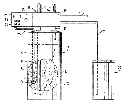
Referring to Fig. 1, a water conditioning or softening apparatus
or device 10 is illustrated having a control unit 11. The water conditioning
apparatus 10 includes a water tank 12 containing a bed 13 of suitable ion
exchange resin. In order to provide water to the tank, a water supply line 14
is connected via valve housing 16 which passes the water through a pipe 17
extending to the tank 12. The water passes down through the bed 13 and is
removed via pipe 18 through the valve housing 16 to a line 19 which supplies
the softened water to the water system. A conduit 21 extends from the valve
control to a brine tank 22 which contains salt for forming the brine. A drain
conduit 23 is also connected to the valve housing 16 and is connected to a
suitable drain.
The control valve structure 16 may be of a type that is well
known to those skilled in the art, and the specific control valve structure
does
not form a part of the present invention. A recycling control 24 controls the
recycling of the system and is controlled by a microprocessor-controlled
circuit
26, which is illustrated schematically and in block form in Fig. 2. Control
circuit 26 is connected via lines 25 to two pairs of vertically mounted
electrodes RS and Rr, which are mounted in a suitable holding probe unit 27
(Fig. 1) which extends down into the water tank 12. Electrodes RS and R~ are
vertically spaced relative to each other for detecting the impedance
difference
of the solution in the water tank between the electrodes RS which form ,
sensing cell Rs and electrodes R~ which form reference cell RT.
4
CA 02217735 1997-10-08
WO 97/30940 PCT/LTS97/02393
In Rak et al. U.S. Patent No. 4,299,698, spaced electrodes RS
~ and Rr are used for determining when regeneration of the water softener
should occur for energizing a latching circuit. The present invention
' contemplates utilizing the spaced sensing cell and reference cell for
detecting
the three stage phenomena in order to determine when the slow rinse cycle
is completed and thereby to utilize the three stage phenomena for water
conservation, diagnostics, and to eliminate any source of possible error in
the
setting of the slow rinse time. In this manner, variations in water pressure
are
compensated for. Further, by utilizing the three stage phenomena, in the
present invention the rinse time can be adjusted to be precise. This is in
sharp contrast to typical prior art softening systems which utilize a fixed
slow
rinse cycle. The fixed time is typically based on a look-up table that is
based
on the salt dosage and the hardness of the water.
In the process of water softening, there are a number of steps.
The first step is the backwash step in which the water enters the unit in
reverse. The water flows from the bottom to the top of the water tank and
the purpose of the backwash is to remove any large particles and to loosen the
bed so that it is not overly compacted.
The next step is the brine/draw and brine/rinse. This step has
two functions. Its first function is to introduce brine into the water
softener
tank 12 from brine tank 22 via conduit 21. Microprocessor control circuit 26
decides how much brine should be drawn in and that is programmed through
a salt dosage setting. The number of pounds of salt is entered via keypad 28,
displayed on display 29, and the software decides how much water should be
put into the brine tank based on the entered number of pounds of salt.
Brine is drawn in for a number of minutes until a specific gravity
detector valve at the bottom of the brine tank causes the brine/draw cycle to
. discontinue and the cycle is then changed to a slow rinse cycle. In
accordance
with the present invention, the three stage phenomena is utilized to determine
5
CA 02217735 1997-10-08
WO 97/30940 PCT/US97/02393
when the slow rinse cycle should be discontinued. To this end, when the rinse
cycle begins, the bed of the water softener is surrounded totally by sodium
ions. As hard water enters into the water tank 12, it enters from the top of
the tank via conduit 17 and it starts to form a low sodium/high sodium front '
at the top of the tank. This front will gradually advance downward towards
the bottom of the tank and end up in the middle of the cells RS and Rr. This
is the second stage. Thereafter, the low sodium/high sodium front moves
down the tank beyond the lower, reference cell indicating that the water in
the
bed is now fresh and that the slow rinse can be discontinued. This is the
third
state and the slow rinse cycle can be discontinued a short predetermined time
after the third state is achieved.
The circuit for controlling the cycles is illustrated in Fig. 2.
Referring to Fig. 2, reference cell Rr and spaced sensing cell RS carried by
. probe 27 (Fig. 1) are connected via lines 30, 31 and 32 to pins 1, 2 and 3
of
plug 34. Pin 4 is connected to the microprocessor 26 via line 35 with a
resistor 36 present to prevent the microprocessor 26 from any latchup
condition. Resistor 38 and capacitor 39 operate as an indicator to indicate to
microprocessor 26 that the probe is present (i.e., it has been plugged in) and
this provides the appropriate signal to the microprocessor. When the probe
27 is not plugged in there will be a 5 volt signal and when the probe is
plugged in the pins 4 and 5 of plug 34 will be shorted so there will be a zero
volt signal.
Reference cell R,. forms one arm of a wheatstone bridge circuit.
. Sensing cell RS forms another arm of the wheatstone bridge circuit. The
probe is excited with an AC voltage across points 40 and 41. The AC voltage
prevents scaling in that if a DC voltage were used, scaling could be present
on
the cells Rr and R5. Resistor 42 forms another arm of the wheatstone bridge
and resistor 43 forms the fourth arm of the wheatstone bridge. Capacitor 44 ,
is used as a filter capacitor to prevent RF noise from affecting the circuit
or
6
CA 02217735 1997-10-08
WO 97/30940 PCT/US97/02393
. false signals. The output of the wheatstone bridge is connected to
comparator
w 46, the output of which is an open collector device that can be either off
or
on depending on whether the probe is in balance or out of balance.
' Comparator 46 itself has an internal transistor. When the comparator is off,
S the output of the comparator is a half wave rectified signal resembling a
trapezoid signal. When the comparator is on, the output of the comparator
is a DC voltage.
Thus when the comparator 46 is off, there is a DC voltage at the
output of diode 48 and wheel the comparator is on, the output of diode 48 is
at ground. When the comparator is on the cells are balanced and when the
comparator is off the cells are unbalanced. At states 1 and 3 the comparator
is on and at state 2 the comparator is off.
A diode 50 and resistor 51 are connected in series to point 52
between the output of comparator 46 and the anode of diode 48. The phase
relationship at point 53 is critical to the phase relationship of the AC
signal
at points 40 and 41.
The output of diode 48 is coupled through resistor 54 to an
NPN transistor 56. Transistor 56 operates to turn the DC voltage at the
output of diode 48 into a zero to 5 DC volt signal for the microprocessor 26.
Thus the circuit of Fig. 2 operates to determine whether the
probe with cells Rr and RS is balanced or unbalanced. In the first stage, the
probe is balanced, and in the second stage the probe is unbalanced; and in the
third stage the probe is balanced again.
A flowchart showing the microprocessor-controlled regeneration
is illustrated in Figs. 3a-3e and a flowchart showing the microprocessor-
controlled self-adjusting slow rinse subroutine is illustrated in Figs. 4a-4c
Referring to Figs. 3a-3e, after start (60) a determination is made
whether the regeneration is armed (61). This determination is made based
upon the impedance difference of the solution in the water tank between the
7
CA 02217735 1997-10-08
WO 97130940 PCT/US97/02393
reference cell Rr and the sensing cell RS. If regeneration is armed, a
determination is made whether it is the time of day for regeneration to occur
(62). As an example, the system may be set so that regeneration can only
occur between 2:00 a.m. and 6:00 a.m. If it is regeneration time, then '
regeneration is started (63) and the motor is turned on (64). A determination
is made whether the motor is at backwash (65). If it is set to backwash,
backwash time is loaded (66) and backwash will continue until the timer times
out (67). Once the timer times out the motor is turned on (68) and a
determination is made whether the motor is at brine draw/slow rinse (69). If
it is at brine draw/slow rinse, the chlorinator time is loaded (70) and the
slow
rinse time is also loaded {71). The chlorinator relay is turned on (72) and a
determination is made when the chlorinator timer times out (73). Once the
chlorinator timer times out, the chlorinator relay is turned off (74).
A determination is made whether the probe is attached (75).
If it is attached, the self adjusting slow rinse subroutine is called (76).
A flowchart showing the slow rinse subroutine is set forth in
Figs. 4a-4c. This flowchart will be discussed below but first a completion of
the discussion of the flowchart of Figs. 3a-3c will be completed.
Referring now to Fig. 3d, after the slow rinse subroutine is
performed (77) (which will be described below in association with Figs. 4a-4c)
the motor is turned on {78) and a determination is made as to whether the
motor is at fast rinse position {79). Once the motor is at fast rinse
position,
the motor is turned off (80) and the fast rinse time is loaded into the timer
(81). When the fast rinse timer times out (82), the motor is turned on (83)
and a determination is made whether the motor is at home position (84). If
the motor is at home position the motor is turned off (85) and regeneration
is complete (86).
Referring to Figs. 4a-4c, a flowchart of the self adjusting slow ,
rinse subroutine is illustrated. First, as set forth in Fig. 3b, when the
motor
8
CA 02217735 1997-10-08
WO 97130940 PCT/US97102393
is at brine draw/slow rinse, a maximum slow rinse timer is loaded (71). This
timer can be loaded with, for example, 99 minutes (a longer time than the
entire cycle should take) so that if the maximum slow rinse timer times out
' and this upper time limit of 99 minutes is reached, the system shuts off
S indicating that there is an aberration.
Referring back to Fig. 4a, a state timer is loaded (90) and
started (91). A determination is made whether the probe is in state 1 (92).
If the probe is not in state 1, the state timer is reloaded (90) and it
continues
to be reloaded until a determination is made that the probe is in state 1.
Once the determination is made that the probe is in state 1, a determination
is made whether the maximum slow rinse timer has time out (93). If it has
timed out (meaning the upper time limit has been reached), the cycle is
discontinued because there is a problem. If the upper time limit (in this
example 99 minutes) has not been reached, a determination is made whether
15the state timer has timed out {94).
In the illustrative embodiment {although no (imitation is
intended), the state timer for state 1 may be five minutes. Thus once five
minutes has expired since the probe is in state 1, the state timer is loaded
for
the state 2 time (96) (Fig. 4b) and the state timer is started (97). A
determination is made if the probe is in state 2 (98). So long as the probe is
not in state 2, the state timer is reloaded {96) until the probe is in state
2.
Once the probe is in state 2 a determination is made whether the maximum
slow rinse timer has timed out (99) and if it has timed out and the upper time
limit has been reached (100), the cycle is discontinued (101), indicating that
there is a problem. If the upper time limit has not been reached, a
determination is made whether the state timer has timed out (102). If the
state timer has timed out the state timer is loaded with the time for state 3
(104). In the illustrative embodiment, the state 2 time is preferably about
five
minutes although no limitation is intended.
9
CA 02217735 1997-10-08
WO 97/30940 PCT1US97/02393
Referring to Fig. 4c, the state timer is loaded {104) and started
(105) and a determination is made if the probe is in state 3 (106). So long as
the probe is not in state 3, the state timer is reloaded (104). Once the probe
is in state 3, a determination is made if the maximum slow rinse timer has
timed out (107) and if so, the cycle is discontinued indicating a problem
(I08).
So long as the upper time limit has not been reached, a determination is made
whether the state timer has timed out (110). If the state timer has timed out,
this indicates that state 3 has been completed and then the motor will be
turned on (Fig. 3d) and a determination will be made if the motor is at a fast
rinse position. In the illustrative embodiment, the timer for the third state
is
set to 15 minutes although no limitation is intended.
It is to be understood that the particular times set forth above
can be varied and no limitation is intended by the specific times set forth
herein. Further, flip flops could be utilized so that the first state could be
an
unbalanced state, the second state could be a balanced state and the third
state could be an unbalanced state. Further, instead of determining whether
the probe is in a particular state and reloading the state timer if it is not
in
the particular state, the state timer could be loaded and then not started
until
the determination is made that the probe is in the particular state.
Although an illustrative embodiment of the invention has been
shown and described, it is to be understood that various modifications and
substitutions may be made by those skilled in the art without departing from
the novel spirit and scope of the present invention.