Note: Descriptions are shown in the official language in which they were submitted.
CA 02217788 1997-10-29
TITLE
QUICK-ERECTING TENT
FIELD OF THE INVENTION
The present invention relates to tents, and more
particularly, to tents that can be quickly and easily
erected by one person and stored compactly.
From the perspective of campers, ease of erecting
and breaking down the tent is very important because
campers are often eager to continue with their planned
activities, and do not want to waste time and effort
building tents. This is particularly important to
campers who arrive at their campsite after dark or in
inclement weather. Ease of set-up by a single person
is also advantageous.
Another very important factor is the compactness
of the tent when it is collapsed. Tents are very often
carried to a camping ground, and a small package makes
this much easier to do. Small packages are also easier
to store.
CA 02217788 1997-10-29
DESCRIPTION OF RELATED ART
Tents that can be disassembled and stored in a
compact configuration have been available for some
time. Typically, these tents use support poles that
can be detached from the tent canopy and then either
disassembled into multiple parts or folded upon
themselves. However, to erect these tents, the pole
segments must be sorted and properly reassembled or
unfolded, and each pole must then be connected to the
tent canopy. It would be preferable to minimize the
number of separate parts that must be assembled,
thereby reducing the number of steps required to set up
the tent.
U.S. Patent No. 4,945,936, to Surrendi, which is
incorporated herein by reference, is directed to an
attempt to address this problem with a collapsible, or
"umbrella", tent frame. In Surrendi, a tent frame 1
includes four legs, each of which includes a lower
section 2 and an upper section 3. The two sections are
pivotally connected by a pivot connector 4, and the
upper section is pivoted to an upper clevis member of a
clevis assembly 5.
The clevis assembly 5 comprises identical upper
and lower clevis members 10, 11 and a center post 12.
As best seen in Figures 2 and 5 of Surrendi, the center
post 12 has a main body 18 diameter and smaller
diameter upper and lower portions 19, 21. The lower
end is secured to the lower clevis member 11.
Each upper leg section 3 is provided with a pivot
member 27 at a point intermediate its length. Radial
brace members 28 each have one end pivoted to one of
members 27 and the other end pivoted to the lower
clevis member 11. The positions of members 27 and the
CA 02217788 1997-10-29
length of members 28 are such that when the tent is
erected, as seen in Figure 1, the lower clevis member
11 is forced upwardly, so that the upper portion 19 of
the center post 12 is received in a through-bore 14 of
the upper clevis member.
While this frame provides umbrella-like
collapsibility, numerous problems remain. First,
because the frame is disposed within the tent canopy,
it is relatively inaccessible, which can make it
difficult to raise and lower the tent. Further, with
Surrendi's configuration, it would be difficult to
incorporate a rainfly (i.e., an outer canvas) that is
separated from the inner canopy to increase water and
wind resistance.
Yet another drawback of Surrendi is that it relies
only on the tension of the canvas to hold the center
post 12 in the bore 14 of the upper clevis member.
Because no other mechanism is used to hold the center
post 12 in the bore 14, if the center post were to be
pulled away from the bore with sufficient force to
overcome the tension of the canvas, the tent would
collapse. Since the tent is intended for use in
unpredictable environs, this can cause serious
problems.
SUMMARY OF THE INVENTION
The present invention advantageously provides a
tent which can be stored in a compact configuration and
can be erected quickly and easily by one person.
According to one aspect of the present invention,
a tent that includes a collapsible frame is provided.
A plurality of fasteners are slidably connected to the
frame, and a canopy is connected to the fasteners so
CA 02217788 1997-10-29
-- 4
that the canopy is supported by the frame when the
frame is erected. The bottoms of the legs of the frame
are connected to respective locations on the canopy,
and stake rings are elastically connected to the
canopy.
According to another aspect of the invention, a
tent is provided. The tent includes a primary support
frame having at least three support legs extending from
and pivotally secured to a primary hub. Each support
leg has an upper leg portion and a lower leg portion.
The tent also includes a secondary support frame
including at least three leg braces extending from and
pivotally secured to a secondary hub, with each leg
brace having an outer end pivotally secured to a
corresponding support leg. A canopy is disposed within
these two support frames, and slidably attached to at
least one of the support frames. A plurality of straps
with an opening, a stake ring, and an elastic portion
therebetween extend from the bottom of the canopy. The
opening receives the bottom of a leg, which is held in
place by a fastener, and the stake ring receives a
stake to secure the tent. The primary hub and the
secondary hub have mating structures that mate when the
hubs are moved together.
According to another aspect of the invention, a
tent is provided. The tent includes a primary support
frame having at least three support legs extending from
and pivotally secured to a primary hub. Each support
leg has an upper leg portion and a lower leg portion.
The tent also includes a secondary support frame
including at least three leg braces extending from and
pivotally secured to a secondary hub, with each leg
brace having an outer end pivotally secured to a
corresponding support leg. A canopy is disposed within
CA 02217788 1997-10-29
these two support frames, and slidably attached to at
least one of the support frames. A lower end of each
leg is secured to peripheral locations of the canopy.
The primary hub and the secondary hub have mating
structures that mate when the hubs are moved together,
and a fastener keeps the hubs together when the mating
structures are mated.
According to another aspect of the invention, a
tent is provided. The tent includes a primary support
frame having at least three support legs extending from
and pivotally secured to a primary hub. Each support
leg has an upper leg portion hingedly attached to a
lower leg portion. The tent also includes a secondary
support frame including at least three leg braces
extending from and pivotally secured to a secondary
hub, with each leg brace having an outer end pivotally
secured to a corresponding support leg. A canopy is
disposed within these two support frames, and slidably
attached using C-shaped clips to at least one of the
support frames. A lower end of each leg is secured to
peripheral locations of the canopy. The primary hub
and the secondary hub have mating structures that mate
when the hubs are moved together.
BRIEF DESCRIPTION OF THE DRAWINGS
The present invention will be explained in
conjunction with an illustrative embodiment shown in
the accompanying drawing, in which:
Figure 1 is a partial perspective view of a tent
formed in accordance with a preferred embodiment of the
present invention;
Figure 2 is a detailed perspective view of the top
of the tent shown in Figure 1;
CA 02217788 1997-10-29
Figure 3 is a detailed perspective view of
portions of a support leg and the tent canopy, and two
slidable support clips, of the tent shown in Figure l;
Figure 4 is a perspective view of the tent shown
in Figure 1, collapsed and rolled up for storage;
Figure 5 illustrates an early step of erecting the
tent shown in Figure l;
Figure 6 illustrates the tent of Figure 1,
partially erected;
Figure 7 is a detailed view of a portion of the
tent as illustrated in Figure 6;
Figure 8 illustrates the tent of Figure 1 with
partially raised primary and secondary support frames;
Figure 9 illustrates the tent of Figure 1 with a
fully raised primary support frame and the secondary
support frame in a below-horizontal position;
Figures 10, 11, and 12 sequentially illustrate
movement of the secondary frame from the below-
horizontal position shown in Figure 9 to an above-
horizontal position;
Figure 13A is a detailed, disassembled perspective
view of a corner of the tent canopy and an end of a
support leg of the tent shown in Figure l;
Figure 13B is a detailed, disassembled perspective
view of a corner of the tent canopy and an end of a
support leg of a tent in accordance with another
preferred embodiment of the present invention;
CA 02217788 1997-10-29
Figure 14 illustrates the attachment of the end of
the support leg and the corner of the tent canopy shown
in Figure 13; and
Figure 15 is a sectional view taken along the line
15-15 of Figure 3.
DETAILED DESCRIPTION OF THE PREFERRED EMBODIMENTS
Figure 1 illustrates a tent 20 of a preferred
embodiment of the present invention in its erected
position. The tent includes a canopy 21 and a
supporting frame 22. The canopy 21 can be formed from
conventional tent fabric including, for example, nylon
and canvas. The illustrated canopy includes a
substantially dome-shaped top 23 and a floor 24.
Preferably, the top includes four substantially
triangular panels 25 connected along seams 26 which
converge at an apex 27. The bottom edges 28 of the
panels are connected to the floor 24, forming a
substantially rectangular bottom periphery. The panels
and bottom are preferably stitched together, but can
also be connected by any other conventional means. One
of the panels is provided with an opening 29 that can
be closable by a flap 30. This four panel canopy is
preferred for use with the four leg supporting frame 22
discussed herein. It will be appreciated that the
canopy 21 can be varied to accommodate supporting
frames 22 having different dimensions or a different
number of legs.
The tent canopy 21 is supported in the erected
position shown in Figure 1 by the supporting frame 22.
The frame 22 includes a primary support frame 31 and a
secondary support frame 32. As best seen in Figures 2,
3 and 15, the canopy 21 is slidably attached to the
primary and secondary support frames 31 and 32. In the
CA 02217788 1997-10-29
preferred embodiment, clips 34 slidably attach the
canopy to the support frames and allow sliding along
the direction of the frame members. The clips 34 are
preferably formed of plastic, but can be also be formed
of metal, wood, or other appropriate materials. As
best seen in Fig. 15, the preferred clips 34 are C-
shaped to provide the added advantage of being snap-
fittable onto and off of the frame 22. These C-shaped
clips facilitate the initial assembly of the tent by
the manufacturer. Of course, this can be alternatively
achieved by any of a number of chips or like devices
which can be snapped onto the frames for slidable
engagement.
The chips in this embodiment are secured to the
canopy by tabs 33, which may be formed from woven
fabric. The tabs may be inserted through the clips 34
and stitched into the seams 26 of the canopy 21.
Alternatively, the clips 34 may each be provided with
an integral base tab which can be affixed directly to
the canopy 21, whether stitched into a seam or inserted
through a specially provided opening.
Alternatively, the canopy 21 can be secured to the
supporting frame 22 by means other than the tabs and
clips shown. For example, the canopy 21 could be
secured by complementary tabs which snap or hook
together around the frame 22, hooks or clips attached
directly to the canopy, or sleeves or loops disposed on
the outside of the canopy. Other suitable arrangements
can be readily envisioned. It is important, however,
for the connection between the canopy 21 and the frame
22 to be slidable.
The primary support frame 31 includes four support
legs 36, with which the seams of the canopy 21 are
preferably aligned. The upper end of each support leg
CA 02217788 1997-10-29
36 is pivotally attached to a primary hub 41 (in this
embodiment, a clevis) by a pin 42 or the like. Other
suitable means of pivotal engagement can be used,
including, but not limited to, ball joints and sturdy
flexible straps.
The bottom end of each support leg 36 is connected
to a respective corner of the canopy 21. Preferably, a
strap 44 (best seen in Figures 13A, 13B and 14) for
receiving the support leg extends from each corner of
the canopy 21. Each strap 44 is preferably formed of a
suitably sturdy material, such as woven fabric. Each
strap 44 can be provided with an opening 45, which can
be reinforced by a metal grommet 46 or the like. It
will be appreciated that alternate structures can be
provided to serve the function of the grommetted
opening 45.
The bottom end of each support leg 36 preferably
includes a cylindrical enlargement 48 and a reduced
diameter end portion 49 which fits through the opening
45 in the strap. An E-ring 50 or other suitable clip
can snap into an annular groove 51 in the end portion
49 to secure the grommet 46 between the enlargement 48
and the E-ring 50. Alternatively, the support legs 36
can be secured to the corners of the canopy 21 by other
means. For example, an additional E-ring or the like
can be used in place of the enlargement 48, or screw-on
end cap could be used in place of the E-ring 50.
Preferably, a stake ring 47 is provided at the end
of each strap 44 (shown in Figure 13A). In the
embodiment shown, a D-ring is employed as the stake
ring 47. A tent stake can be driven through this stake
ring to secure the canopy 21 to the ground or other
support surface. Alternative configurations of stake
rings 47 may also be used in place of the D-ring shown
CA 02217788 1997-10-29
-- 10 --
in the drawings. For example, a circular ring may be
provided at the end of the strap 44. As yet another
alternative, a second opening can be provided in the
strap itself and reinforced with a grommet or the like,
similar to the opening 45 and grommet 46. Numerous
other stake ring configurations can be readily
envisioned, including stake rings with non-circular
shapes, such as squares or rectangles. The important
thing is that the stake ring must be able to secure the
tent when a stake is driven into the stake ring.
Optionally, as shown in Figure 13B, an elastic
span 44A can be disposed at each corner of the tent
between the opening 45 and the stake ring 47. This
permits the bottom end 49 of each support leg 36 to
move around even though the tent corners are staked in
place, which eases the erecting and collapsing of the
tent. The elastic span 44A may be sewn to the end of
strap 44, or connected in another suitable way. The
elastic span 44A may be constructed of a suitably
strong fabric with rubber strands woven into the
fabric. The elastic span 44A stretches when the tent
is being erected, and eventually returns to
approximately its original length.
When an elastic span 44A is used, a second stake
ring 52 may be added to the strap on the canopy side of
the elastic span. This second stake ring 52 can then
be used if a non-elastic stake connection is desired.
The camper can drive a stake through the first stake
ring 47 when initially erecting the tent, and then
drive a stake through the second stake ring 52 to
further secure the tent after the tent has been
erected.
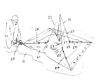
Figure 4 shows a compact configuration in which
the tent is stored. To erect the tent, the camper
CA 02217788 1997-10-29
unrolls the canopy 21, and raises the tents to the
position shown in Figure 5. He then unfolds the tent
to the position shown in Figure 6. It is apparent from
this view that each support leg 36 includes an upper
leg portion 53 hinged to a lower leg portion 54. As
discussed, the canopy 21 is connected to the bottom of
the lower leg portions 54. Thus, unfolding the support
legs 36 in this manner will spread the canopy 21 on the
ground G.
In the position shown in Figures 6 and 7, the
upper leg portions 53 form a self-supporting pyramid.
Preferably, the lower leg portions 54 are hingedly
connected to the upper leg portions 53 using hinges 55.
These hinges permit the upper and lower leg portions 53
and 54 to pivot relative to one another within a range
of between about 0~ and about 180~, but do not let the
leg portions rotate beyond about 180~.
With the tent in this position, before erecting
the tent further, the corners of the tent may be staked
to the ground G by driving stakes 68 through the stake
rings 47 (shown in Figure 13A and 13B).
As discussed, the upper end of each upper leg
portion 53 is connected to the primary hub 41, and the
lower end of each lower leg portion 54 is attached to a
respective corner of the canopy 21. These leg portions
53 and 54 are preferably glass-filled nylon rods, but
can be formed of other suitable material, including,
but not limited to, metal and wood.
A secondary support frame is provided inside the
pyramid of the primary support frame. The secondary
support frame includes four leg braces 57, each
corresponding to one of the support legs 36 of the
primary support frame. The leg braces may be formed of
CA 02217788 1997-10-29
- 12 -
the same materials as the support legs 36. The inner
end of each leg brace 57 iS pivotally connected to a
central secondary hub 61 (in this embodiment a clevis).
The outer end of each leg brace 57 iS pivotally
connected, by way of a connector 58, to a respective
one of the upper leg portions 53 of the support legs
36. Preferably, each connector 58 includes a pin that
allows the leg brace 57 to pivot.
Figures 8 and 9 show the tent being raised
further. To accomplish this, the secondary hub 61 (not
visible in these views) is lifted with one hand, which
raises the inner ends of the leg braces 57. Meanwhile,
the primary hub 41 (not shown) is steadied with the
other hand. As the inner ends of the leg braces 57 are
raised, the outer ends of the leg braces 57 will be
spread apart, pushing the support legs 36 apart.
When the leg braces 57 arrive at the position
shown in Figure 8, the leg braces 57 are approximately
perpendicular to the upper leg portions 53. In this
position, the secondary hub 61 iS spaced a maximum
distance from the support legs 36, the canopy hook 34
on each leg brace 57 iS still located near the inner
end of the leg brace, and the support frame is not yet
self-supporting.
As the inner ends of the leg braces 57 are raised
further, the upper leg portions 53 are pushed further
apart. This will cause the upper and lower leg
portions 53 and 54 to pivot at the hinges 55,
straightening the support legs 36. Once the support
legs 36 are approximately straight, the hinges 55 will
not open any further, as explained above. The clips 34
attaching the canopy to the support legs 36 will slide
along the upper and lower legs 53 and 54 due to the
tension created between the legs and the canopy 21.
CA 022l7788 l997-l0-29
- 13 -
Because the bottoms of the lower leg portions 54 are
connected to the canopy 21, which is connected to a
non-elastic floor 24, as the upper leg portions 53 are
forced further out by the leg braces, the support legs
36 will bow out as illustrated in Figure 9.
Figures 10, 11, and 12 show a more detailed view
of the upper portion of the support frame as it is
being moved into its erect position.
The sliding attachments between the canopy 21 and
the two support frames are an important aspect of the
present invention. The clips 34 are free to slide
along the support legs 36 and the leg braces 57. This
allows the canopy 21 to slide with respect to the
frame, which permits the legs to be folded and unfolded
without interference from the canopy 21. Preferably,
starting from the center of the canopy, one clip 34 iS
attached to each leg brace 57, one clip 34 iS attached
to each upper leg portion 53 between the hinge 55 and
the connector 58, and three clips 34 are attached to
each lower leg portion 54.
As the inner ends of the leg braces 57 are raised
closer to the upper ends of the support legs 36, the
inner ends will rise above the outer ends of the leg
braces 57. As soon as this occurs, the tension from
the canopy squeezing the support legs 36 together will
start to urge the secondary hub 61 upwards, towards the
primary hub 41. In addition, as the secondary hub 61
approaches the primary hub 41, the tension from the
canopy 21 causes the canopy clips 34 on the leg braces
57 to slide outward on the leg braces.
A tube 37 depends from the primary hub 41.
Preferably, the tube 37 iS a three part telescoping
tube including a top tube 38 having a closed top, an
CA 02217788 1997-10-29
- 14 -
intermediate tube 39, and a bottom tube 40. An
elongated pin 60 extends upward from the secondary hub
61. The pin 60 and telescoping tube 37, which can be
formed of metal, plastic, or another suitable material,
are engageable with each another.
The telescoping tube 37 extends downwardly from
the center of the primary hub 41 for a substantial
distance to receive and guide the pin 60 as the pin is
raised. As the pin 60 moves upwards, the tube 37
collapses, as shown in Figure 12. In this position,
the support frame is self-supporting. The telescoping
tube 37 retains the pin 60 and keeps the leg braces 57
centered with respect to the support legs 36. The
telescoping feature of the tube 37 aids in the mating
with the pin 60, but it is not required.
While the drawings show a pin 60 mating with a
tube 37, alternative male and female mating structures
may also be used. For example, a slot may be mated
with a matching ridge, or a convex dome may be mated
with a concave bowl. Numerous other mating structures
can be readily envisioned. In addition, while the
drawings show a male pin 60 attached to the secondary
hub 61, and a female tube 37 attached to the primary
hub 41, the male and female structures can be
interchanged so that the male structure is attached to
the primary hub 41 and the female structure is attached
to the secondary hub 61.
When the tent is erect as illustrated in Figures 1
and 2, the pin 60 is seated in the telescoping tube 37.
The tension from the tent canopy 21 is translated to
the leg braces and the support legs 36 through the tabs
33 and sliding clips 34. The leg braces 57 of the
secondary support frame extend out and down from the
secondary hub 61 from which the pin 60 extends.
CA 022l7788 l997-l0-29
- 15 -
In this position, the leg braces 57 push outward
against the support legs 36 and prevent the support
legs 36 from collapsing inwardly. The leg braces 57
are retained in the raised position by tension from the
canopy 21 which squeezes the support legs 36 and the
outer ends of the leg braces 57 together, while the
telescoping tube 37 holds the secondary hub 61 and the
inner ends of the leg braces 57 in place. As long as
the secondary hub 61 remains in place next to the
primary hub 41, the frame will remain erect and support
the canopy 21.
Figure 2 depicts the top of the support frame when
the tent is assembled in its self-supporting position.
Optionally, to ensure that an unforeseen force does not
pull the secondary hub 61 away from the primary hub 41,
which would cause the tent to collapse, a fastener can
be added to hold the hubs 41 and 61 together. For
example, straps 64 and 65 can be permanently secured to
the apex of the canopy 21 and tied around the
interconnected pin 60 and telescoping tube 37. This
would prevent the pin 60 from separating from the
telescoping tube 37, holding the leg braces 57 in their
bracing position. Alternative fasteners may also be
used in place of straps 64 and 65. For example, a
cotter pin may be inserted into a hole drilled through
the hubs, or the two hubs may be clamped together.
Numerous other alternative fasteners can be readily
envisioned.
Tents in accordance with the present invention can
be erected quickly and easily by one person. It is
possible to erect these tents from the position shown
in Figure 4 to the position shown in Figure 1 in under
60 seconds, including time for staking the corners of
the tent.
CA 022l7788 l997-l0-29
- 16 -
Once the tent has been erected, as described
above, it can be used just like any conventional tent.
After the tent is used, it can be collapsed and folded
for storage by reversing the procedure used to erect
the tent. More specifically, the straps 64 and 65 are
untied, and the pin 60 and the inner ends of the leg
braces 57 are pulled downwardly away from the
telescoping tube 37. Once the leg braces 57 pass below
horizontal, the tension from the canopy 21 transmitted
through the leg braces 57 will tend to push the inner
secondary hub 61 downward, away from the primary hub
41. In this position, the leg braces 57 no longer
support the support legs 36, and the support legs 36
will collapse under the weight of the canopy 21.
The primary and secondary support frames can then
be collapsed for storage by folding the pivoting leg
portions 53 and 54 of the support legs 36 against one
another and against the leg braces 57. As this is
done, the canopy clips 34 slide relative to the support
legs 36 and leg braces 57.
Once the frame is collapsed, the canopy 21 can be
wrapped around the frame so that the tent can be stored
2 5 in the compact configuration shown in Figure 4.
While the present invention has been described
above with reference to the specific embodiments, it is
to be understood that the invention is not limited to
those precise embodiments. Changes and modifications
can be effected without departing from the scope or
spirit of the present invention.