Note: Descriptions are shown in the official language in which they were submitted.
CA 02217805 1997-10-07
IRI03621 CA
METHOD AND INTELLIGENT DIGITAL BEAM FORMING SYSTEM
RESPONSIVE TO TRAFFIC DEMAND
Field of the Invention
This invention relates to the field of phased array
antennas and in particular to digital beam forming.
Background of the Invention
Satellite communication systems have used phased
array antennas to communicate with multiple users through
multiple antenna beams. Typically efficient bandwidth
modulation techniques are combined with multiple access
techniques and frequency separation methods are employed
to increase the number of users. However, with the
electronic environment becoming increasingly dense with
the proliferation of wireless personal communication
devices such as cellular telephones and pagers, even more
information and sophistication are required for these
wireless communication systems. For example, with all the
users competing for the limited frequency spectrum, the
mitigation of interference between the various systems is
a key to the allocation in the spectrum to the various
systems.
Furthermore, the concept of spectral sharing, e.g.,
the ability of multiple systems to simultaneously use
common spectrum, is of major importance to governmental
bodies such as the Federal Communications Commission (FCC)
granting communication licenses to satellite system
operators.
Thus what is needed is a communication system that
mitigates interference between other systems while sharing
spectrum with those other systems. Thus, what is also
needed are an apparatus and method that can share and
provide for the sharing spectrum with other communication
systems.
-1-
CA 02217805 1997-10-07
IRI03621 CA
Although a variety of techniques for beam forming
have been developed, current digital beam forming antenna
systems lack the computational performance required by
many communication system applications. Consequently,
there is a need for a digital beam forming system that
provides high-performance computational power at low cost.
Brief Description of the Drawings
The invention is pointed out with particularity in
the appended claims. However, a more complete
understanding of the present invention may be derived by
referring to the detailed description and claims when
considered in connection with the figures, wherein like
reference numbers refer to similar items throughout the
figures, and:
FIG. 1 shows a block diagram of satellite receiver
and transmitter portions incorporating a digital beam
former in accordance with a preferred embodiment of the
present invention;
FIG. 2 shows a block diagram of a ground terminal
and an array antenna including a digital beam former in
accordance with the preferred embodiment of the present
invention;
FIG. 3 illustrates a geostationary satellite using a
digital beam former in accordance with a preferred
embodiment of the present invention sharing spectrum with
a non-geostationary satellite;
FIG. 4 illustrates a satellite providing individual
antenna beams using a digital beam former in accordance
with the present invention;
FIG. 5 illustrates antenna beam projections on
earth's surface using a digital beam former in accordance
with a preferred embodiment of the present invention that
are responsive to demand for communication services;
FIGS. 6 and 7 are flow charts illustrating an
interference mitigation and antenna beam assignment
-2-
CA 02217805 1997-10-07
IRI03621 CA
procedure in accordance with a preferred embodiment of the
present invention;
FIG. 8 is a flow chart illustrating a procedure for
providing antenna beams to geographic regions in response
to demand for communication services;
FIG. 9 shows a block diagram of a digital beam
former in accordance with a preferred embodiment of the
present invention;
FIG. 10 shows a block diagram representing a first
embodiment of a computing unit suitable for use in the
digital beam former of the preferred embodiment of the
present invention;
FIG. 11 shows a block diagram representing a second
embodiment of a computing unit suitable for use in the
digital beam former of the preferred embodiment of the
present invention;
FIG. 12 shows a block diagram representing a third
embodiment of a computing unit suitable for use in the
digital beam former of the preferred embodiment of the
present invention;
FIG. 13 shows a block diagram representing a first
embodiment of a summing processor suitable for use in the
digital beam former of the preferred embodiment of the
present invention;
FIG. 14 shows a block diagram representing a second
embodiment of a summing processor suitable for use in the
digital beam former of the preferred embodiment of the
present invention; and
FIG. 15 shows a block diagram of a digital beam
former that is in accordance with a second embodiment of
the present invention;
The exemplification set out herein illustrates a
preferred embodiment of the invention in one form
thereof, and such exemplification is not intended to
be construed as limiting in any manner.
-3-
CA 02217805 1997-10-07
IRI03621 CA
rSUMMARY OF THE INVENTION
The present invention provides, among other things,
a digital beam former suitable for use in array antennas.
In the preferred embodiment the digital beam former
provides a method of mitigating interference from
interfering signals. The present invention also provides
a method of tracking the location of interfering signals
and readjusts the digital beam forming coefficients to
create nulls in the antenna pattern directed towards that
interfering signal. The present invention also provides a
digital beam former that mitigates interference from
interfering signals.
The present invention also provides a method of
communicating with communication terminals, subscriber
units, relays or aircraft using an array antenna having a
digital beam former. In a preferred embodiment, digital
beam forming coefficients are adjusted to improve or
maximize the signal quality of communication signals
received from the communication terminals. In one
embodiment of the present invention, the communication
terminal provides the satellite with quality indicators
which indicate the quality of the signals received by the
communication terminal. In response to received link
quality indicators, the digital beam former on board the
satellite dynamically adjusts its antenna beam pattern to
help optimize the signal transmitted to the communication
terminal. In another embodiment of the present invention,
the digital beam forming coefficients are readjusted to
continually help maintain and help improve or maximize the
signal quality of the received signals as the
communication terminal and the satellite change their
relative positions.
The present invention also provides a method of
communicating with communication terminals using a digital
beam former on board a satellite based array antenna.
The digital beam former coefficients are adjusted to
-4-
CA 02217805 1997-10-07
IRI03621 CA
provide more antenna beams to geographic regions having
high demand for communication services and also adjusted
to provide fewer antenna beams to regions having a low
demand for communication services. In the preferred
embodiment, as the demand for communication services
changes with respect to geographic location, the digital
beam former of the present invention dynamically assigns
antenna beams or assigns additional beams in response to
the changes in demand for communication services. The
present invention also provides a communication terminal,
such as a subscriber unit, that communicates with
satellites, communication stations or other communication
terminals using an array antenna configured with a digital
beam former.
Detailed Description of the Drawings
Analog array antennas are well known in the art.
Antenna beam characteristics are controlled by adjusting
the amplitude and phase of the received or transmitted
signal of each array element. Through these controls,
each antenna beam can be shaped, its pointing direction
can be defined, antenna nulls can be directed, etc.
Multiple amplitude and phase adjustments can be used to
create multiple antenna beams. Because of the complexity
of these systems, most analog array antennas that generate
multiple beam patterns are phased arrays that use a butler
matrix to combine the signals from each array element. In
general, once a butler matrix and combining network is
built the characteristics of the antenna beams remain
fixed. In the present invention a digital beam former is
used to dynamically control the amplitude and phase of
each of the radiating elements to form multiple antenna
beams. Characteristics of the beams such as pointing
direction of the main beam, pointing direction of any of
the other beams, the bandwidth, location of nulls,
corrections for aperture irregularities and other
-5-
CA 02217805 1997-10-07
IRI03621 CA
characteristics of the beams are all controlled through
the use dynamic adjustment of the beam coefficients. Such
flexibility is not possible in analog phased array
implementations.
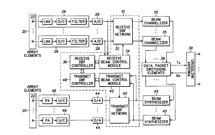
FIG. 1 shows a block diagram of satellite receiver
and transmitter portions incorporating a digital beam
former in accordance with a preferred embodiment of the
present invention. Digital beam former 10 includes a
receive digital beam forming (DBF) network 32, receive
beam control module 34, receive DBF controller 36,
transmit DBF network 40, transmit beam control module 42
and transmit DBF controller 48. The receiver portions
include receive portion of array-antenna 20, one or more
receiver modules 26, and one or more analog-to-digital
(A/D) converters 28.
Beam former 10 implements beams steering and control
functions necessary to form antenna beams with the desired
characteristics. The digital outputs that beam former 10
provides to each beam channelizer 35 are preferably
equivalent to the output of either a signal single antenna
beam. These digital outputs are routed through the packet
switching elements to either appropriate cross-link or
down-link communication paths. In the case of down-links
the process is reversed.
The transmit digital beam forming network 40 applies
the appropriate beam steering and beam control vectors to
each of these signals forming down-link beams with the
prescribed characteristics. These baseband signals are
converted back to analog signals and translated to down-
link frequencies. Power amplifiers preferably drive each
of the individual array elements. The transmitter portion
includes one or more digital-to-analog (D/A) converters
44, one or more transmitter modules 46, and transmit
portion of array-antenna 20.
The array-antenna 20 includes elements 22 preferably
arranged in a two-dimensional array, however other array
configurations are suitable. Received radio frequency
-6-
CA 02217805 1997-10-07
IRI03621 CA
(RF) signals are detected and digitized at the element
level. In the absence of fading, the received signals
have generally equal amplitudes, but different phases at
each element. The signals can represent any number of
communication channels.
In response to the received signals, the receiver
modules 26 generate analog signals. The receiver modules
26 perform the functions of frequency down-conversion,
filtering, and amplification to a power level commensurate
with the A/D converter 28. The phase information of the
radiated signals is preserved via an in-phase (I) and
quadrature (Q) component included in the analog signal.
The I and Q components respectively represent real and
imaginary parts of the complex analog signal. There is
preferably a one-to-one correspondence between the
elements 22 and receiver modules 26.
The A/D converters 28 sample and digitize the analog
signals to produce digital signals. Each A/D converter is
preferably dedicated to processing the signals produced by
a respective array element. After the A/D conversion, the
digital signals go to the receive digital beamforming
network 32 which computes weighted sums representing
inner-product beams. Typically, an inner-product beam
represents a single communication channel.
Weight values are passed to receive digital
beamforming network 32 by the receive beam control module
34. Using a suitable algorithm, receive beam control
module 34 adaptively determines the proper weights for
each radiating element 22. This can be done a relatively
slow rate compared to the overall data throughput of the
antenna system. Receive DBF controller 36 analyzes
incoming signals and performs procedures and processes
discussed below.
Receive DBF network 32 provides digital signals
received from each radiating element 22 to beam
channelizers 35. The digital signals includes amplitude
and phase information (I and Q) from the radiating
CA 02217805 1997-10-07
IRI03621 CA
elements. Each beam channelizer module converts these
digital signals to a digital data stream for one
particular antenna beam or channel. Preferably, each
channelizer module corresponds with one antenna beam.
Beam channelizer modules 35 provide this digital data
stream to data packet switching elements 38 from which the
data is packetized and the packets are routed accordingly.
In the preferred embodiment, the data packets are routed
over crosslinks antennas 39 to other satellites, over
downlinks to gateways or earth terminals, or over
downlinks provided by the satellite to communication
terminals. Preferably, array-antenna 20 provides both
uplinks and downlinks for the communication terminals.
Incoming de-packetized data from data packet
switching elements 38 are provided to beam synthesizer
modules 45. Data packet switching elements 38 provide a
digital data stream representing one individual antenna
beam to each beam synthesizer module 45. The incoming
digital signals preferably include phase information (I
and Q components) for each channel/antenna beam. Beam
synthesizer modules 45 convert this digital data stream to
a digital output signal that represents the analog
waveforms for each transmit radiating element 22. Each
beam synthesizer module 45 provides its digital output
signal to both transmit digital beam forming network 40
and the transmit beam control module 42. Transmit beam
control module 42 provides weighted sums to transmit
digital beam forming network 40. Preferably, a weighted
sum is provided to correspond with each of the transmit
radiating elements 22 of the array-antenna 20.
The weights are passed to the digital beam forming
network 40 by transmit beam control module 42. Using a
suitable algorithm, the transmit beam control module 42
adaptively determines the proper weights.
D/A converters 44 convert the digital output signals
for each radiating element of the beam forming network 40
into corresponding analog signals for each radiating
_g_
CA 02217805 1997-10-07
IRI03621 CA
element 22. Transmitter modules 46 generate signals
suitable for transmission by the radiating elements and
preferably perform the functions of frequency up-
conversion, filtering, and amplification.
The digital beam forming antenna system shown in
FIG. 1 has advantages over conventional fixed beam
antennas because it may, among other things, separate
closely spaced users, adaptively adjust beam patterns in
response to incoming data, provide antenna beams to
individual users, provide antenna beams in response to
demand for communication services and improve pattern
nulling of unwanted RF signals. These features are
implemented through appropriate software embedded in
controllers 36 and 48.
FIG. 2 shows a block diagram of a communication
terminal and an array antenna including a digital beam
former in accordance with the preferred embodiment of the
present invention. Communication terminal 90 may be a
mobile terminal, a ground station, a relay station or a
communication terminal such as a mobile or cellular
telephone, and may be mobile or fixed in location.
Communication terminal 90 may also be on board an
aircraft. Communication terminal 90 is coupled to array
antenna 89. Array antenna 89 is comprised of a plurality
of radiating elements, preferably arranged in a two-
dimensional array configuration. Each array element
preferably provides for reception and/or transmission of a
RF signals. Because of the properties of antennas, the
description herein is equally suitable to transmission and
reception.
Communication terminal 90 includes isolators 91,
which separate the received and transmitted signals from
array antenna 89. Isolators 91 provide a transmit signal
from transmit modules 93 for each array element by
transmit modules 93. Isolators 91 provide received
signals from each array element to receive modules 92.
Ground terminal 90 also includes a digital beam former 10
_g_
CA 02217805 1997-10-07
IRI03621 CA
(DBF) which preferably includes transmit digital beam
forming network 94, receive digital beam former network 98
and digital beam former controller 99. Transmit digital
beam forming network 94 receives beam forming coefficients
from DBF controller 99 which control the phase and
amplitude components of the transmitted RF signals at each
radiating element of array antenna 89. Receive digital
beam forming network 98 receives beam forming coefficients
from DBF controller 99 to provide for phase and amplitude
adjustment of the received RF signals from the array
elements or array antenna 89.
Transmit modules 93 are similar to and perform
similar functions to transmit modules 46 of FIG. 1.
Receive modules 92 are similar to and perform similar
functions as receiver modules 26 of FIG. 1. Transmit
modules 93 convert I and Q digital signals received from
transmit digital beam forming network 94 to analog signals
while receive modules 92 convert analog signals to I and Q
digital signals and provide these I and Q digital signals
to receive digital beam forming network 98. Receive
digital beam forming network 98 provides a channelized
output digital signal to digital signal processor (DSP) 95
which represents the communication channel signal on which
the ground terminal is communicating. In one embodiment
of the present invention, ground terminal 90 may
communicate on several channels at the same time.
Accordingly, receive digital beam forming network 98
provides a signal for each communication channel to DSP
95.
In this embodiment DSP 95 also provides a
communication channel signal to transmit digital beam
forming network 94 for each communication channel the
ground terminal communicates on. In the case of a
cellular telephone or mobile telephone that communicates
on one communication channel, receive DBF provides one
communication channel to DSP 95 while DSP 95 provides one
transmit communication channel to transmit digital beam
-10-
CA 02217805 1997-10-07
IRI03621 CA
forming network 94. There is no requirement that the
transmit and receive communication channels be the same.
DSP 95 in conjunction with Input/output section (I/O) and
in conjunction with memory element 97 provide all the
standard functions associated with operating mobile
terminal ground stations, communication terminals such as
subscriber units, or cellular telephones. In general
array elements or array antenna 89, transmit and receive
digital beam forming networks 94 and 98 and DBF controller
99 are similar to the respective elements of FIG. 1.
Communication terminal 90 is preferably configured to
communicate using time-division multiple access (TDMA),
frequency-division multiple access (FDMA) or code-division
multiple access (CDMA) methods.
In the case of a subscriber unit, less array
elements are required than in a satellite phase array
antenna. Accordingly, the received DBF and transmit DBF
modules have less elements associated therewith. For
example, in the satellite phased array antenna of FIG. 1,
a preferred embodiment of the preferred invention uses 64
sets of 8x8 radiating elements. These 4096 radiating
elements preferably use 4096 associated receiver modules
26 and transmitter modules 46. Accordingly, 4096 analog
to digital (A to D) or digital to analog (D to A)
converters 28 and 44 are also used. Each A to D converter
preferably provides 16 I bits and 16 Q bits of data.
Receive DBF network has 4096 times 16 inputs from the A to
D converters. The number of I and Q bits, may be more or
less than 16 and the number of radiating elements depends
on several factors, including the link margin, signal to
noise ratio and antenna beam characteristics. For
example, in subscriber unit and mobile and cellular
telephone applications, the number of radiating elements
may be between 8 and a few hundred. While for mobile and
ground terminals that handle many different communication
channels through many different antenna beams the number
of radiating elements may be several hundred to several
-11-
CA 02217805 1997-10-07
IRI03621 CA
thousand. The communication terminal of FIG. 2,
communicate with a satellite or other communication
station, or another subscriber unit or commmunication
terminal through the use of digital beam former 88.
Digital beam former 88 includes transmit digital
beam forming network 94, receive digital beam forming
network 98 and digital beam forming controller 99.
Digital beam former 88 has similar functionality and
includes similar hardware elements as digital beam former
10 of FIG. 1.
Through the use of digital beam former 88 embodied
in subscriber unit or communication terminal 90 of FIG. 2,
communication terminal 90 in one embodiment of the present
invention tracks interfering signals and provides a null
in its antenna pattern in the direction of the interfering
signal. For example, when the ground station communicates
with geostationary satellites, an interfering signal may
result from a low Earth orbit satellite moving across the
sky. Terminal 90 also tracks, in another embodiment of
the present invention, other interfering signals and
provides for nulling the antenna pattern in the direction
of those interfering signals. In another embodiment of
the present invention communication terminal 90, attempts
to improve its receipt of incoming signals by adjusting
its receiver DBF coefficients for improved signal
qualities such as signal to noise ratio or carrier to
noise plus interference ratio.
In another embodiment of the present invention,
communication terminal 90 receives a link quality
indicator from a communication station or satellite (or
another communication terminal) that it is communicating
with. The link quality indicator (LQI) provides
preferably 3 data bits indicating of the quality of the
signal received at the satellite receiver or ground base
station receiver. This link quality indicator is provided
back to the ground terminal or subscriber unit which
accordingly adjusts its transmit digital beam forming
-12-
CA 02217805 1997-10-07
IRI03621 CA
coefficients dynamically to improve the quality of its
transmitted signal. In this embodiment DSP 95 evaluates
the link quality indicator and directs DBF controller 99
to adjust the beam forming coefficient provided to
transmit digital beam forming network 94. In general this
causes the transmit and receive antenna beam
characteristics to be more optimized for the particular
situation the subscriber unit or communication terminal is
currently experiencing. The situation includes
interference characteristics from other signals,
interference characteristics caused by ground terrain and
the specific receiver antenna characteristics of the
receiving base station and/or satellite.
In another embodiment of the present invention the
subscriber unit and/or communication terminal 90 tracks
the communication signal from the base station and
satellite as the subscriber unit or ground terminal moves.
For example mobile subscriber units track the direction of
the ground station or satellite which they are
communicating with. This tracking is done by one of a
variety of ways including using the receive signal and
analyzing the angle or direction of arrival of the receipt
signal. Alternatively, as the subscriber unit moves, the
antenna beams, preferably both transmit and receive, are
continually adjusted to help improve signal quality.
Accordingly, the resulting antenna beam patterns are
directed towards the communication station, while nulls
are directed toward any interfering signal source. In one
embodiment of the present invention, the subscriber unit
is adapted for communicating with satellites and in non-
geostationary orbit such as satellites in a low Earth
orbit. As the satellite passes overhead, the antenna beam
characteristics, through the use of the digital beam
former 88, are adjusted to maintain improved communication
with the low Earth orbit satellite and preferably remain
directed towards the satellite as the satellite moves
across the sky.
-13-
CA 02217805 1997-10-07
IRI03621 CA
An example of the subscriber unit and antenna array
89 of FIG. 2 would include array elements mounted on a
roof of a motorized vehicle coupled to communicatoin
terminal 90 located inside the vehicle. In the case of
ground terminal, array elements may be mounted on the roof
of a house or building and the ground terminal may be
located elsewhere.
FIG. 3 illustrates a geostationary satellite with a
digital beam former in accordance with a preferred
embodiment of the present invention sharing spectrum with
a non-geostationary satellite. FIG. 3 illustrates a
typical spectrum sharing scenario in which the present
invention may be used. As illustrated, there are several
line-of-sight paths between geostationary (GSO) satellite
62 and non-geostationary (NGSO) satellite 60, NGSO
terminal 68, GSO ground terminal 66 and an interfering
signal source 64. Because NGSO satellite 60 is not fixed
in relation to Earth's surface, NGSO satellite may come
into view at various time. If the two communication
systems occupy a common segment of the frequency spectrum,
interference between the two systems may occur.
When GSO satellite 62 employs a digital beam former
of the present invention, the receiver portion of the
digital beam former configures the antenna beams of GSO
satellite to desirably point its main communication beam
at the ground GSO terminal 66 while preferably providing a
null in the antenna pattern in the direction of NGSO
ground terminal 68. Accordingly, any interference from
the NGSO ground terminal 68 is significantly reduced.
Preferably another null in the antenna pattern of GSO
satellite 62 is directed toward and tracks NGSO satellite
60. To accomplish this, DBF receive and/or transmit
coefficients are continually adjusted to maintain a null
in the direction of the NGSO satellite 60 as the NGSO
satellite 60 moves. Accordingly, these nulls are
dynamically controlled.
-14-
CA 02217805 1997-10-07
IRI03621 CA
Nulls are placed in the antenna pattern directed to
towards NGSO terminal 68. NGSO terminal 68 usually
transmits and receives at a time only when NGSO satellite
is overhead. Accordingly the null in the transmit and
receive antenna patterns of GSO satellite 62 may be turned
on and turned off in accordance with NGSO terminal 68.
The positioning of a null in the receive and transmit
antenna patterns of GSO satellite 62 allows the two
systems to share spectrums. In the preferred embodiment
of the present invention, transmit and receive nulls are
placed in similar directions. The direction information
is preferably shared between received DBF controller 36
and transmit DBF controller 48 of FIG. 1.
In one preferred embodiment, the direction to direct
the antenna null is determined using direction of arrival
information from the interfering signal. DBF of GSO
satellite 62 monitors its field of view for preferably two
classes of signals, synergistic and non-synergistic:
Synergistic signals are signals whose characteristics are
well-known. Preferably these synergistic interfering
signals are demodulated in GSO satellite 62 at baseband
level and accordingly transmit and receive digital beam
forming coefficients are adjusted to reduce and help
minimize the receipt of this interfering signal. In the
case of non-synergistic signals, i.e., signals that are
unknown, basic direction of arrival techniques are used to
mitigate interference from these signals.
The digital beam former of the present invention may
also be employed on NGSO satellite 60 and provide nulls in
the direction of GSO terminal 66 and interfering signal
source 64.
One advantage to the present invention is that
spectral sharing is improved for increased geostationary
satellite density. For example, through the use of the
digital beam former described in FIG. 1, geostationary
satellites may be placed in orbital slots separated by
less than 2°. For example, when a communication terminal
-15-
CA 02217805 1997-10-07
IRI03621 CA
is communicating with its assigned geostationary
satellite, each of the geostationary satellite are
broadcasting acquisition channel information. The
communication terminal antenna receives this information
from each of the satellites within view. When the
acquisition channels are separable in some way, such as
frequency, the ground terminal preferably receive each
acquisition channel and determines the direction of
arrival of each of the acquisition signals. The digital
beam former, when employed in a geostationary satellite
ground terminal, preferably adjusts its transmit and
receive antenna beam characteristics to point its primary
antenna beams at the desired geostationary satellite while
directing a null in the direction of the other
geostationary satellites. The direction of arrival may be
determined using, among other things, information
associated with the communication terminal's location.
Super resolution techniques allow the spatial
resolution of these signals separate by approximately
1/lOth of an antenna beam width. To maintain such fine
separation, high values of signal to noise ratio are
desirably. Accordingly, a ground station with a suitable
amount of array elements 22 (FIG. 1) provides for an
acceptable signal to noise ratio and suitable antenna beam
gain characteristics.
In another embodiment the present invention, the
digital beam former as embodied aboard a geostationary
satellite maintains antenna alignment. For example, GSO
satellites slowly drift in their orbital locations.
Typically, onboard station keeping is required to maintain
the satellites position. As a SO satellite drifts, its
antenna beams move off their intended pointing direction
and various alignment techniques based on the transmission
of frequency tones from the system control facility are
typically used to realign the pointing direction of the
satellite antennas. GSO satellite antenna systems based
on reflector or lens antennas correct for these movements
-16-
CA 02217805 1997-10-07
IRI03621 CA
by physically moving the antennas or the antenna feeds.
Such a technique requires that antenna components be noted
on moveable structures. The digital beam former of the
present invention eliminates the need for these mechanical
structures. The digital beam former corrects the beam
pointing direction as the geostationary satellite drifts.
This correction is preferably based on the use of
transmitted or received signal quality levels.
FIG. 4 illustrates a satellite providing individual
antenna beams using a digital beam former in accordance
with the present invention. Satellite 50 may be either a
geostationary satellite or non-geostationary satellite.
Satellite 50 has a footprint region associated therewith
which is the geographic region satellite 50 provides
communication services. Satellite 50 may cover footprint
region 53 with one antenna beam for signals from within
the footprint regions, including the monitoring demand for
communication services, monitoring interfering and
monitoring subscriber units requesting service. Satellite
50 also provides a plurality of individual antenna beams
52 within footprint region 53. A digital beam former in
accordance with the present invention is configured to
provide these antenna beams. Individual antenna beams 52
are provided in a variety of ways and are preferably
provided to individual subscriber unit. Individual
antenna beams 52 are also provided in response to demand
for communication services. Individual antenna beams 52
track a subscriber unit's movement through the footprint
region 53. These are described in more detail in the
procedures below.
FIG. 5 illustrates antenna beam projections on a
portion of Earth's surface using a digital beam former in
accordance with a preferred embodiment of the present
invention. In this embodiment, antenna beams are provided
in responsive to demand for communication services. The
ability to adapt to traffic demand is very desirable in
any satellite system. Digital beam former 10 of FIG. 1
-17-
CA 02217805 1997-10-07
IRI03621 CA
provides for positioning of nulls in the antenna beam
pattern and provides for beam shaping and other beam
characteristics that are dynamically modified through the
use of these digital beam forming techniques. In a
preferred embodiment of the present invention, the digital
beam former 10 provides dynamically reconfigurable antenna
patterns such that is shown in FIG. 5. These example
antenna beam patterns are based on current traffic demand
levels. For example, antenna beam 74 provides broad
coverage over a large region having a low demand for
communication services, while antenna beams 80 are small
and provide a high concentration of communication capacity
in a region having high demand for communication services.
In another embodiment, antenna beams are shaped in
responsive to demand for communication services. Antenna
beams 74 are modified and shaped, for example, to
approximate the contour of a geographic region having high
demand for communication services next to an area having
virtually no demand for communication services, e.g., the
ocean. Accordingly, communication capacity may be
concentrated where it is needed. In the preferred
embodiment, antenna beam 70 are dynamically configured in
real time in response to demand for communication
services. However, in other embodiments of the present
invention, antenna beams are provided based on historic
and measured demand for communication services.
FIGS. 6 and 7 are flowcharts illustrating an
interference mitigation and antenna beam assignment
procedure in accordance with the preferred embodiment of
the present invention. Procedure 100, although shown in a
top down sequential flow is meant to illustrate the steps
performed by digital beam former 10 of FIG. 1. Many of
the tasks and steps shown are preferably performed in
parallel and procedure 100 is desirably performed for many
subscriber units and interfering signals concurrently.
Those of skill in the art are able to write software for
receive DBF controller 36 and transmit DBF controller 48
-18-
CA 02217805 1997-10-07
IRI03621 CA
to execute the tasks of procedure 100. Preferably
procedure 100 is performed by receive DBF controller 36
and transmit DBF controller 48 in conjunction with beam
controller modules 34 and 42. Software is embedded within
DBF controller 36, transmit DBF controller 48, and beam
controller module 34 to perform the functions described
herein. Portions of procedure 100 may also be performed
concurrently by processors on other satellites or ground
stations in conjunction with the satellite portion shown
in FIG. 1. Although procedure 100 is described for
communication between a satellite and a ground based
subscriber unit, procedure 100 is applicable to any
communication station, including relay stations and
communication terminals.
In task 102, the communication station listens for
signals, preferably within the satellite's footprint.
Preferably, receive beam controller module 34 configures
the antenna beams to provides at least one broad antenna
beam covering substantially an entire satellite footprint.
Accordingly, signals are received from anywhere within
that footprint on that one antenna beam. Signals that are
received may include signals from existing users that are
already communicating with the satellite system,
interfering signals, e.g., signals from non-system users
including interfering signals, and signals from system
users requesting access to the system.
Task 104 determines whether or not the signal is one
from an existing user. In general, the location of
existing users is known. If the signal received is not
from an existing user, task 106 determines the location of
that signal source. Those of skill in the art will
recognize that various ways may be used to determine the
geographic location of a signal source. Those ways may
include analyzing the angle of arrival, the time of
arrival, frequency of arrival, etc. Alternatively, if the
signal source is a user requesting system access, that
-19-
CA 02217805 1997-10-07
IRI03621 CA
subscriber unit may provide geographic coordinates on its
system access request signal.
Once the location of the signal source is determined
task 110 determines whether or not the signal is an
interfering signal. In other words, task 110 determines
if the signal source will interfere with a portion of the
spectrum assigned to the satellite system, or
alternatively, if the interfering signal is a
communication channel currently in use with a subscriber
unit communicating with the satellite. If task 110
determines that the signal source is not an interfering
signal and that the signal source is a request for a new
channel, task 112 assigns an antenna beam to that user.
Task 112 may employ various security and access request
procedures which are not necessarily important to the
present invention. In the preferred embodiment task 112
is accomplished through receive and transmit DBF
controllers 36 and 48 providing the appropriate
information to beam control modules 34 and 42.
Beam control modules 34 and 42 cause receive and
transmit DBF network 32 and 40 to generate individual
receive and transmit antenna beams directed to that
subscriber unit at that subscriber units geographic
location. Tasks 114 and 116 preferably, repeatedly adjust
the DBF transmit and receive coefficients to help provide
improved signal quality received from the subscriber unit.
In one preferred embodiment of the present invention
the subscriber unit provides a link quality indicator
(LQI) that indicates the quality of the received signal.
The subscriber unit provides that link quality indicator
to the satellite. The link quality indicator is evaluated
by received DBF controller 36 and transmit DBF controller
48 causing transmit beam control module 42 to adjust DBF
control coefficients to help optimize the transmitted
antenna beam to the subscriber unit.
When task 110 determines that the signal source is
an interfering signal, for example a non-system user, task
-20-
CA 02217805 1997-10-07
IRI03621 CA
118 and task 120 calculate and adjust the receive DBF
coefficients provided to receive DBF network 32 to help
reduce or minimize interference from the interring signal.
In one embodiment of the present invention, task 118
places a "null" in the antenna pattern in the direction of
the interfering signal. In the preferred embodiment tasks
118 and 120 are repeated until the interference is below a
predetermined level. In task 122, the interfering signal
is continually monitored and tracked as either the
satellite moves or the interfering signal moves.
When task 104 has determined that the signal source
is an existing user, task 124 determines when a hand-off
is required. In some embodiments of the present invention
the subscriber unit requests hand-offs while in other
embodiments of the present invention, the system
determines when a hand-off is necessary. Preferably,
hand-offs are determined based on signal quality. In
general, a hand-off is requested when a user is near the
edge of the antenna pattern footprint region or exclusion
zone.
In one preferred embodiment of the present
invention, antenna beams are individually provided to the
subscriber unit and the individual antenna beam tracks the
location of the subscriber unit. Accordingly, hand-offs
are only between satellites and necessary at the edge of
the satellite footprint. When a hand-off is necessary,
task 112 is executed which assigns a new antenna beam from
another satellite to the user. If a hand-off is not
required, task 128 is executed. In task 128, in-band
interference is monitored along with received power level
and link quality metrics.
In task 132, the receive and transmits DBF
coefficients are adjusted to help maintain an improved or
maximum signal quality, to help reduce or minimize in-band
interference and to help maximize receive power level.
During this "tracking" mode, additional interfering
signals 130 may cause a degradation in signal quality.
-21-
CA 02217805 1997-10-07
IRI03621 CA
Accordingly, task 132 dynamically readjusts the DBF
coefficients to help maintain signal quality. In one
embodiment of present invention link quality indicators
131 are provided by communication terminals or subscriber
units. Accordingly, the combination of tasks 128 through
132 provide for tracking of the subscriber unit as the
relative location between the subscriber unit and the
satellite change. Task 134 determines when a hand-off is
required. If a hand-off is not required the subscriber
unit remains in the tracking mode. When the hand-off is
required task 136 will execute a hand-off to the next
satellite. In one embodiment of the present invention the
next satellite is notified that a hand-off is required and
it is provided the geographic location of the subscriber
unit. Accordingly, the next satellite can assign and
generate an antenna beam specifically for that subscriber
unit before being released from its present satellite.
Once the subscriber unit is handed off to the next
satellite, task 138 adds the available antenna beam to its
resource pool, allowing that antenna beam to be available
to be assigned to another subscriber unit.
FIG. 8 is a flowchart illustrating a procedure for
providing antenna beams to geographic regions in response
to demand for communication services. Procedure 200,
although shown in a top down sequential flow is meant to
illustrate the steps performed by digital beam performer
10 of FIG. 1. Many of the tasks and steps shown are
preferably performed in parallel and procedure 200 is
desirably performed for many subscriber units
concurrently. Those of skill in the art are able to write
software for receive DBF controllers 36 and transmit DBF
controller 48 to execute the tasks of procedure 200. The
tasks of procedure 200 are preferably performed on a
continual basis by receive and transmit DBF controllers 36
and 48. Although procedure 200 is described for
communication between a satellite and a ground based
subscriber unit, procedure 100 is applicable to any
-22-
CA 02217805 1997-10-07
IRI03621 CA
communication station, including relay stations and
communication terminals.
In task 202 the demand for communication services is
monitored within the satellite footprint region. In the
preferred embodiment, one antenna beam is used to monitor
the demand throughout the entire footprint. In task 204
the location of high demand and low demand geographic
regions are determined. Task 204 can be accomplished in
any number of ways. For example, each subscriber unit
communicating with the system has a geographic location
associated therewith. Furthermore, each subscriber unit
requesting access to the system may provide the system
with geographic location data. Once the geographic
locations of high demand and low demand areas are
determined, task 206 causes the DBF beam control modules
to provide less antenna beams in low demand areas and
provide more antenna beams in high demand areas. In one
embodiment of the present invention, each antenna beam
provides a limited amount of communication capacity.
Referring to FIG. 5, lower demand areas are provided
with antenna beams having a much larger coverage region
than antenna beams being provided to high demand areas.
For example, antenna beam 74 of FIG. 5 covers a large
geographic region that currently has a low demand for
communication services. Alternatively, antenna beams 80
have much smaller geographic coverage regions and provide
more communication capacity for a region that currently
has a high demand for communication services. In another
embodiment of the present invention tasks 206 and 208
adjust the shape of the antenna beams based on the demand
for communication services. For example, in reference to
FIG. 5, antenna beams 74 are long narrow beams formed to
provide better area coverage for communication services.
For example, coastal regions are provided narrow beams to
reduce communication capacity over the ocean where
significantly less communication capacity is required. In
this embodiment, antenna beams 74 are preferably shaped
-23-
CA 02217805 1997-10-07
IRI03621 CA
dynamically in response to demand for communication
services.
As the demand for communication services changes,
antenna beams 70 are dynamically provided in response.
For example, FIG. 5 shows a continental view of the United
States communication services. As the day begins, antenna
beams are initially provided along the East Coast of the
United States. As the day progresses, the antenna beams
transition across the country as the time of day changes
in response to demand for communication services. In the
case of a natural disaster where demand for communication
services may be particularly great, dedicated antenna
beams may be provided. A satellite control facility may
direct satellite's digital beam former 10 to allocate
beams accordingly. In general, antenna beams 70
preferably are provided in response to the changing demand
of communication services without the assistance of
operators.
FIG. 9 shows a block diagram of the digital beam
former according to an embodiment of the present
invention. The beam former includes a plurality of
computing units (CU's) 160-176 and a plurality of summing
processors 180 - 184. The computing units 160-176 form a
processor array. Each column in the processor array
receives a corresponding digital signal. Upon receiving a
digital signal, each computing unit independently weights
the signal to generate a weighted signal. The summing
processors 180 - 184 provide a means for summing weighted
signals generated by a respective row to produce outputs.
Essentially, each output signal represents a weighted sum.
The architecture of the digital beam former lends itself
to high-speed, parallel computation of discrete Fourier
transforms.
FIG. 10 shows a block diagram representing a first
embodiment of a computing unit usable in the digital beam
former of FIG. 9. The computing unit includes a
multiplier 190 and a memory circuit 192. The computing
-24-
CA 02217805 1997-10-07
IRI03621 CA
unit weights an incoming digital signal by multiplying it
by a pre-computed weight value stored in the memory
circuit 192. The output of the multiplier 190 represents
the weighted signal.
The memory circuit 192 can be any means for storing
values whose contents is up-datable by the digital beam
control modules 34, 42 (FIG. 1), such as a ROM (read only
memory), EEPROM (electrically erasable programmable read
only memory), DRAM (dynamic random access memory), or SRAM
(static random access memory).
FIG. 11 shows a block diagram representing a second
embodiment of a computing unit usable in the digital beam
former of FIG. 9. In this embodiment of the computing
unit, an incoming signal is weighted using logarithmic
number system (LNS) arithmetic. LNS-based arithmetic
provides advantage because multiplication operations can
be accomplished with adders instead of multipliers.
Digital adder circuits tend to be much smaller than
comparable multiplier circuits, thus, the size the beam
forming processor array can be reduced by incorporating
LNS-based computing units.
The LNS-based computing unit includes a log
converter 210, an adder 212, a memory circuit 214, and an
inverse-log (log-1) converter 216. An incoming signal is
first converted to its respective log signal by the log
converter 210. The adder 212 then sums the log signal and
a logged weight value from the memory circuit 214 to
produce a sum. The sum is then converted to the weighted
signal by the inverse-log converter 216.
The log converter 210 and inverse-log converter 216
can be implemented using any of the converters described
in the co-pending U.S. patent applications of above-
identified Related Applications Nos. 1-4.
FIG. 12 shows a block diagram representing a third
embodiment of a computing unit usable in the digital beam
former of FIG. 9. This embodiment of the computing unit
is intended to weight complex signals. In many
-25-
CA 02217805 1997-10-07
IRI03621 CA
applications, the I and Q components of the complex
digital signals are represented by a pair of 3-bit words.
Although it is not limited to small word lengths, the
computing unit of FIG. 12 provides advantage in such
applications because it requires less power and space when
implemented using an integrated circuit.
The computing unit includes a first switch 220, a
first memory circuit 222, a second switch 224, a second
memory circuit 226, a subtractor 228, and an adder 221.
The first memory 222 stores first pre-computed values that
are based on an imaginary weight. The second memory 226
stores second pre-computed values that are based on a real
weight. The purpose of the computing unit is to multiply
these two complex numbers. The first memory 222 stores
the pre-computed values I and Q for the imaginary weight,
while the second memory 226 stores the pre-computed values
I and Q for the real weight. It will be apparent to one
of ordinary skill in the art that using 3-bit words to
represent the complex components and weights would require
each memory to store eight 6-bit words.
The first switch 220 provides a means for addressing
the first memory circuit using either the I or Q component
to select one of the first pre-computed values as the
first memory circuit output. The second switch 224
provides a means for addressing the second memory 226
using either the I or Q component to select one of the
second pre-computed values as the second memory circuit
output.
The subtractor 228 subtracts the first memory output
from the second memory output to generate the weighted in-
phase component that is then included in the weighted
signal. The adder 221 sums the first memory output and
the second memory output to generate the weighted
quadrature component that is also included in the weighted
signal.
In one embodiment of the computing unit, the
subtractor 228 includes an adder capable of summing 2s
-26-
CA 02217805 1997-10-07
IRI03621 CA
complement numbers. The pre-computed values are either
stored in the memory as 2s-complement values or additional
logic circuitry is placed in the computing unit to convert
the pre-computed values to their respective 2s-complement
values.
Preferably, the subtractor 228 includes an adder
having a carry input set to one and inverters to form the
1s-complement value of the second memory output. The
adder effectively utilizes the 2s-complement value of the
second memory output by summing the carry input and the
ls-complement value.
FIG. 13 shows a block diagram representing a first
embodiment of a summing processor that is usable in the
digital beam former of FIG. 9. This particular embodiment
of the comprises an adder tree 230. The adder tree 230
includes adders which are connected together in a fashion
which allows three or more input signals to be summed
concurrently. When using the adder tree topology depicted
by FIG. 13, N-1 adders are required to sum N inputs.
Regarding the example shown in FIG. 13, eight input
signals can be received simultaneously, thus, seven adders
are required in the adder tree 230. If one wishes to sum
a greater number of input signals, more adders are
required. For instance, in order to sum 128 input
signals, the adder tree would require 127 adders. The
adder tree 230 has advantage because it presents less of a
delay in providing output sums.
FIG. 14 shows a block diagram representing a second
embodiment of a summing processor that is usable in the
digital beam former of FIG. 9. This summing processor
embodiment includes a plurality of summers 240-248, a
plurality of delay circuits 250-254, and a ripple adder
256. Although this summing processor topology may require
more time to generate a final sum than a comparable adder
tree, it requires less area when implemented in an
integrated circuit.
-27-
CA 02217805 1997-10-07
IRI03621 CA
Each of the summers 240-248 sums weighted signals
from a group of computing units residing in a same row to
produce a weighted sum signal. A summer can include any
means for summing weighted signals, such as an adder tree
or an accumulator that sequentially adds inputs.
The delay circuits 250-254 produce delayed signals
by buffering the weighted sum signals for a predetermined
time. Generally, the weighted signals are produced at the
summer outputs at approximately the same time. In order
to correctly sum the weighted signals, it is necessary to
delay weighted signals that are generated in the
downstream portion of a processor row. The delay time is
a function of the location of the group of computing units
within the processor columns.
The ripple adder 256 includes two or more adders
258-264 cascaded together in order to sum the delayed
signals and first two weighted sums. The output of the
ripple adder 256 represents the total sum of all weighted
signals in a given processor row.
FIG. 15 shows a block diagram of a digital beam
former that is in accordance with a second embodiment of
the present invention. This embodiment of the beam former
includes a log converter 270, a plurality of computing
units 272-288, an inverse-log converter 290, and a
plurality of summing processors 292-296. The computing
units 272-288 form a processor array. Incoming digital
signals are first converted to log signals by the log
converter 270. Each column in the processor array
receives a corresponding log signal. Upon receiving a log
signal, each computing unit independently weights the
signal to generate a sum signal. The sum signals are then
converted to weighted signals by the inverse-log converter
290. For each processor row, the weighted signals are
respectively summed by one of the summing processors 292-
296 to generate an output signal.
The log converter 270 and inverse-log converter 290
can be implemented using any of the converters described
-28-
CA 02217805 1997-10-07
IRI03621 CA
in the co-pending U.S. patent applications identified
above. Although the approach is described in the I and Q
domain, similar techniques are equally applicable to the
polar domain.
The foregoing description of the specific
embodiments will so fully reveal the general nature of
the invention that others can, by applying current
knowledge, readily modify and/or adapt for various
applications such specific embodiments without
departing from the generic concept, and therefore such
adaptations and modifications should and are intended
to be comprehended within the meaning and range of
equivalents of the disclosed embodiments.
It is to be understood that the phraseology or
terminology employed herein is for the purpose of
description and not of limitation. Accordingly, the
invention is intended to embrace all such
alternatives, modifications, equivalents and
variations as fall within the spirit and broad scope
of the appended claims.
-29-