Note: Descriptions are shown in the official language in which they were submitted.
CA 02218100 1997-10-10
WO 96/32544 PCT/SE96/00468
Method and device for performing ground
anchorage
The present invention concerns a method of anchoring in soil by means of a
ground
anchor in the form of a tube in which at least two axial slots are disposed
along at
least one region of a tube wall in a part of the tube which is to be driven
into the
soil, the tube being driven into the soil in co-operation with a pike disposed
in the
tube.
The invention also concerns an arrangement for anchoring in soil, said
axrangement
comprising a ground anchor in the form of a tube on which at least two axial
slots
are disposed along at least one region of a tube wall in a part of the tube
which is to
be driven into the soil.
The invention furthermore concems a tool such that a tubular ground anchor can
be
radially expanded in a controlled manner by the method according to the
invention.
Processes for anchoring soil anchorages which are sunk to a greater or lesser
depth,
for example, when laying foundations, are well known. The currently most usual
type
of anchorage consists of a concrete anchorage cast at the intended anchorage
site.
This type of anchorage is very demanding in terms of time since a casting
mould
firstly has to be dug in the soil before the concrete casting process itself
can be
performed. The concrete then has to be allowed to set before the anchorage is
ready
to be used. A further disadvantage of concrete anchorages is that they tend to
disintegrate after a number of years' use. In order that the durability of the
anchorage
can be checked, it has to be laid bare.
In order to dispense with casting of anchorages it is also known to drive into
the soil
a metal object which, owing to its shape, is anchored in the soil when it has
been
driven in. However this type of anchorage or ground anchor is difficult to
drive into
the soil to a depth sufficient for the anchorage to support high loads. It is
also
already known to drive into the soil a metal tube, for example, which is then
deformed so that reinforcement in the soil is attained.
DE-1 484 565 has already disclosed a ground anchor of the above-mentioned
type. It
CA 02218100 1997-10-10
WO 96/32544 PCT/SE96/00468
2
consists substantially of a tube with a solid tip. A round bar is disposed in
the tube
and connected to the tip. Slots are fonned in the tube above the tip. These
slots are
uniformly distributed along the tube and extend in the axial direction along
the latter.
This ground anchor is anchored in the soil as a result of the round bar and
the tube
disposed about the latter being driven into the soil. When the tube has been
driven
into the soil, an axial, upwardly directed force is applied to the round bar
whilst the tube is held in place by an axially downwardly directed force. The
round bar is
therefore actuated such that it moves upwards out of the tube whilst the tube
tip
approaches the upper part of the tube. The shape of the tube is acted upon in
the
slotted region so that expansion of the tube is brought about in this region.
The
round bar can then be removed from the tube.
A disadvantage of this known type of anchorage is that it is unsuitable for
deep
anchorage and can only be used for ground anchors of very small dimensions.
In the case of large tube dimensions and deep anchorage, the method is
difficult
to cany out, both practically and economically. Furthermore the method is
unsatisfactory when a plurality of expanded regions are desired in each
tubular
anchorage in the ground.
The object of the present invention is to overcome the stated problem by
providing
a soil anchorage consisting of a ground anchor in the form of a tube with
axial slots.
This object is achieved by the method according to the invention which is
characterized in that the tube in at least one region with axial slots is
subjected to
a radial load by means of a tool which is sunk into the tube and which is
actuated
so as to exert a controllable radial load on the interior of the tube in the
direction
towards the tube wall, whereby a controllable expansion of the tube is brought
about
in this region; and in that the tool is removed from the tube when a
predetermined
degree of expansion has been attained.
In order to permit further expansions of the ground anchor, according to a
particular
feature of the invention, each tube comprises two or more regions each having
two
or more slots.
CA 02218100 1997-10-10
WO 96132544 PCT/SE96/00468
3
According to a further particular feature of the invelition, the radial load
is applied in
each slotted region in order to increase the bearing capacity of the
anchorage.
In order to be able to evaluate the bearing capacity of the anchorage,
according to a
further feature of the invention, data concexning expansion are measured
during the
anchorage process, these measured data further being used to provide a
preliminary
geotechnical evaluation of the properties of the soil.
The object of the present invention is also to provide a ground anchor to be
used
according to the above method. This object is achieved by the arrangement
according
to the invention which arrangement is characterized in that the tube is open
over its
entire length and is arranged to be driven into the soil by means of a pike
which is
disposed in the tube and which has a lower pointed end and whose length is
adapted
such that the lower pointed end of the pike projects out of the lower end of
the tube
during the driving-in process; in that, when being driven in, the pike and
tube are
operatively connected to each other at their respective upper ends, such tlhat
these
upper ends can be made to move at the same time as the pike and tube are being
driven in; and in that the pike is arrranged to be removed from the tube when
it has
been driven in, whereupon the tube is arranged such that, at at least two
opposite
points on each side of the interior of the tube, midway between the slots, it
can
receive a radial load brought about by a tool sunk into the tube, the load
being
applied in the direction towards the tube, such that controllable expansion of
the
tube can be brought about in this region.
A further object of the present invention is to provide a tool for bringing
about
the controllable radial expansion of the tubular ground anchor when the method
according to the invention is carried out. This object is achieved by the tool
according to the invention which tool is characterized in that it comprises: a
tool
body adapted such that it can be sunk into the tubular ground anchor; at least
two
radially directed pistons which are disposed at equal spacings and movably
mounted
in corresponding radial recesses in the tool body, which recesses in one
direction
each open out at the periphery of the tool body and in another direction are
each
delimited by a base formed by the tool body; flow connections connecting the
CA 02218100 1997-10-10
WO 96/32544 PCT/SE96/00468
4
recesses at their respective bases to flow attachments on the exterior of the
tool body;
and means for attaching the flow attachments of the flow connections to a
hydraulic
source.
According to a particular feature of the invention, in order to distribute the
force of
the tool uniformly, there are three recesses and three pistons.
According to a further particular feature of the invention, in order to
distribute the
force of the tool uniformly over a large part of the periphery of the ground
anchor
there are four recesses and four pistons.
According to a final particular feature of the invention, the recesses are
located at
mutual substantially similar spacings axially along the length of the tool to
allow a
maxinlum piston stroke when the ground anchor expands.
In the following the invention will be described with reference to the
drawings, in
which:
Figure 1 shows a basic embodiment of a tubular ground anchor,
Figure 2 shows the tubular ground anchor in Figure 1 when it is being driven
into the soil;
Figure 3 shows the tubular ground anchor when the method according to the
invention has been carried out;
Figure 4 shows in side view an example of a tool for carrying out the
controllable radial expansion of the tubular ground anchor by means
of the method according to the invention; and
Figure 5 shows the tool in Figure 4, in perspective.
CA 02218100 1997-10-10
WO 96/32544 PCT/SE96/00468
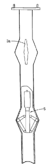
The method according to the invention is intended to be used for tubular
constructions of resilient material, for example a ground anchor 1 in the form
of a steel tube 2. This steel tube is open over its entire length and is
provided in
two different regions of the tube 2 with two axial slots 3a, 3b disposed on
each
5 side of the steel tube. The slotted regions are to be driven into the soil.
During the process of driving into the soil a pike 4 is disposed in the tube
2. This
pike has a lower pointed end 4a which facilitates driving into the soil in
that, as it
is driven in, it projects from the lower end of the tube. The pike reduces the
load
on the tube 2 during the driving-in process at the same time as the ground or
other
material in the soil is prevented from filling the tube. Owing to the pike 4,
the tube 2
can be driven into the ground when it consists of rock or frozen soil. Whilst
being
driven in, the pike 4 and tube 2 are operatively connected to each other at
their
respective upper ends, such that these upper ends can be made to move at the
same time as the pike and tube are being driven in. When the tube 2 has been
driven in to the desired depth, the pike is removed from the tube and can then
be
used again when a further tube is driven in. The driving in process is
performed
mechanically, for example by means of a hydraulic hammer.
When the tube has been driven into the soil a tool 5 is disposed in the tube,
which
tool, in a first collapsed position, can easily be displaced in the tube 2.
This tool can,
for example, consist of the hydraulic tool shown in Figures 4 and 5 but other
tools
are evidently also possible.
The tool 5 according to Figures 4 and 5 is especially adapted for canying out
the
controllable radial expansion of the tubular ground anchor 1. The tool 5
consists
of a tool body 5a which is adapted such that it can be sunk into the tubular
ground
anchor 1. The tool body 5a suitably consists of a solid steel unit. The tool
body 5a
comprises four radially directed pistons 6 which are located at uniform
spacings
about the periphery of the tool and which are movably mounted in corresponding
radial recesses 7 in the tool body 5a. The recesses 7 are located at mutual
substantially similar spacings axially along the length of the tool and each
open
out in one direction at the periphery of the tool body and are delimited in
the other
CA 02218100 1997-10-10
WO 96/32544 PCT/SE96/00468
6
direction by a base formed by the tool body 5a, since the recesses do not pass
through the entire tool body 5a. The recesses 7 are in the form of bores bored
or
milled in the tool body 5a for hydraulic pistons 6. The solid tool body 5a
comprises
flow connections which connect the recesses 7 at their respective bases to
flow 5 attachments 8 on the exterior of the tool body. The flow connections
are to be
attached to a hydraulic source via their flow attachments 8. -
The hydraulic source is advantageously a double-action high-pressure pump with
an operating pressure of up to 1000 bars. Located at the hydraulic source are
arrangements for measuring pressure, flow and other significant parameters.
The possibility of measuring data conceming the expansion, i.e. pressure,
flow, etc.,
whilst carrying out the anchorage process, enables the loads in terms of
pressure,
tension and torque, which the tubular ground anchor can withstand, to be
established.
The measured data can also be used to provide a preliuninary geotechnical
evaluation
of the properties of the soil.
By virtue of the tool the region of the tube comprising axial slots 3a, 3b can
be
loaded in the radial direction. The load is applied on the interior of the
tube in the
direction towards the tube wall in a second, collapsed position of the tool.
In this
position the oil in the tool 5 has been pressurized so that the pistons 6 move
outwards. Since all the recesses 7 are connected for flow to one another, when
one of the pistons reaches maximum pressure, the oil flows on to the next
recess
until all the pistons 6 are in the outer position.
The slots 3a, 3b in the tube enable the latter to be expanded in this region
if the load
is applied at at least two opposite points, disposed on each side of the tube,
midway
between the slots. Expansion or deformation is thereby brought about in the
region
about the axial slots 3a, 3b. The radial expansion of the tube in the slotted
region can
be controlled by guiding the tool 5 sunk in the tube. It is thereby possible
to adapt
the anchorage better to the soil conditions.
If expansion is to be brought about in a given region, the tool is actuated so
as to
CA 02218100 1997-10-10
WO 96/32544 PCT/SE96/00468
7
recover a shape suitable for its displacement in the tube. This is brought
about in
that the double-action hydraulic source is made to return the hydraulic oil
such that
the pistons 6 move into the tool body 5a. The tool 5 is then moved out of the
tube 2
or to a region arranged for further expansion. The same tool can thus be used
for
canying out further expansion of the tube 2 in a different region provided
with axial
slots 3a, 3b. The number of possible expansions in the tube is ultimately
limited to
the number of regions on the tube which are provided with axial slots. It will
be
appreciated that it may also be chosen not to expand the tube in a given
region of the
tube even though this region is provided with axial slots.
The invention provides a method of anchoring in the soil a ground anchor in
the
form of a tube 2, this method being easy to perform. The finished anchorage
comprises a tube 2 which has been deformed in one or a plurality of regions
such
that the radial periphery of the tube 2 has increased in this region or these
regions.
However the tube has been deformed in such a way that cavities in this tube
are
retained over the entire length thereof. It is thereby subsequently easy to
examine
the tube, for example with respect to corrosion damage or the like.
It will be appreciated that the method according to the invention is not
restricted to
the use of the tool as shown in Figures 4 and 5; this tool is only one example
of an
arrangement by means of which radial expansion of a tubular ground anchor can
be
brought about in a given region of this tube.