Note: Descriptions are shown in the official language in which they were submitted.
CA 0221837~ 1997-10-1~
WO 96134589 PC'r~US96~05559
GLUTEAL GROOVE BLOCKING DEVICE FOR DIAPERS
Field and Backqround of the Invention
This invention relates to absorbent articles, and particularly to a diaper
including a part constructed to prevent leakage of fecai material through a
wearer's gluteal groove at the rear of the diaper. While the diaper is de-
scribed herein in its use by a child, it may also be used by adults.
Diapers are, of course, well known and in common use. A disposable
diaper usually includes a core of absorbent material enclosed on its outside
by a liquid impervious backsheet and on its inside by a liquid pervious
topsheet. Such a diaper usually also includes elastic leg cuffs around the
wearer's legs and an elastic waist band around the wearer's waist. A
problem often encountered during use of a conventional diaper as described
above is that fecal material may leak from the rear of the diaper due to activ-
ity by the wearer or when the wearer sits down. The fecal material often
moves through the gluteal groove (the open space between the buttocks),
and in some instances may exit the diaper at the wearer's back. This
situation is, of course, very undesirable because it usually necessitates
additional cleaning of the wearer and, likely, cleaning of clothing and/or
bedding.
Diapers are known in the prior art, having parts which are designed to
extend along the gluteal groove. For example, the K. A. Dreier et al. U.S.
patent No. 5,171,236 describes a "central spacer 56" which has "the
advantage of reducing the amount of fecal material in the gluteal groove of
the wearer". The M. A. Bruemmer et al. U.S. Patent No. 5,176,672
describes a "cleft block 26", one function of which is "to aid in preventing
fecal material from moving up the cleft of the baby's buttocks". The M. E.
Freeland U.S. patent No. 5,306,266 also describes spacers 54 and 66 which
may "plastically deform".
.
CA 0221837~ 1997-10-1~
WO 96134589 PCTIUS96/05559
While the devices described in the prior art patents may function as
purported in the patents, there is a continuing need for a diaper including an
improved device for blocking the movement of fecal materiai along the
gluteal groove of the wearer.
It is therefore a general object of the present invention to provide an
improved diaper including a gluteal groove blocker which retards movement
of fecal material along the gluteal groove and therefore reduces the area of
the wearer's skin soiled by fecal material and the frequency of leakage of
fecal material from the back of the diaper.
Summarv of the Invention
A diaper constructed in accordance with this invention comprises a
core of absorbent core material, a liquid pervious topsheet and a liquid
impervious backsheet, the two sheets enclosing the core and being
attached together. The diaper when placed on a wearer includes a crotch
area, a front area extending toward the wearer's navel, and a back area
covering the wearer's buttocks and gluteal groove. The diaper further com-
prises a blocking part in the back area, the blocking part being constructed
and located to block the gluteal groove and thereby retard the flow of fecal
material rearwardly through the groove. The blocking part conforms well to
the shape of the wearer's body and therefore effectively blocks the groove.
Brief Description of the Drawings
The invention will be better understood from the following detailed
description taken in conjunction with the accompanying figures of the
drawings, wherein:
Fig. 1 is a depiction of a child wearing a diaper constructed in
accordance with the invention;
Fig. 2 is a plan view showing the diaper;
Fig. 3 is a sectional view taken on the line 3-3 of Fig. 2,
CA 0221837~ 1997-10-1~
WO 96134589 PCTfUS96tO~;5S9
- Fig. 4 is a view similar to Fig. 3 but showing an alternative construction
of the diaper;
Fig. 5 is a plan view of a blocking part of the diaper shown in Figs. 1 to
4;
Fig. 6 is a plan view of another blocking part constructed in accordance
with the invention;
Fig. 7 is a sectional view taken on the line 7-7 of Fig. 6;
Fig. 8 is a view similar to Fig. 7 but showing an alternative form;
Fig. 9 is a side view showing still another alternative form of the
blocking part;
Fig. 10 is a sectional view taken on the line 10-10 of Fig. 9;
Fig. 11 is a view similar to Fig. 9 but showing another alternative form;
Fig. 12 is a view similar to Figs. 9 and 11 but showing still another form
of the invention;
Figs. 13 and 14 are views showing still additional forms of the
invention; and
Fig. 15 is a sectional view taken on the line 15-15 of Fig. 14.
Detailed Description of the Invention
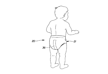
With reference first to Figs. 1, 2 and 3, a wearer 20 (in this instance a
child) is fitted with a diaper 21 which includes a front area 22 (Fig. 2), a
crotch area 23 and a back area 24. When in use, the crotch area 23
extends between the legs of the wearer 20, the front area 22 extends
CA 0221837~ 1997-10-1
WO 96/34589 PCI~/US~)C/05S5
toward the wearer's navel, and the rear area 24 extends over the wearer's
buttocks and over the gluteal groove which separates the two buttocks. The
rear area 24 extends past the rearward end of the groove and to the lower
region of the wearer's back. The back and front borders 26 and 27 (which
may be elastic) extend across the width of the diaper, and fastener tabs 28
are secured to the corners of the diaper. The tabs 28 are, of course,
fastened at the waist to hold the diaper on the wearer when in use. The
edges 29 of the crotch area 23 are preferably elastic. The parts of the
diaper described in this paragraph may have a conventional construction.
Looking at the cross sectional view of the diaper in Fig. 3, it is formed
by a core 31 of a highly absorbent core material. Across the outer side of
the core 31 is a backsheet 32 of a liquid impervious material (such as
plastic), and across the inner side (the skin side) of the diaper is a topsheet
33 of a soft liquid pervious material. The parts 31, 32 and 33 may be
formed of conventional materials in common use for these purposes, such
materials being disclosed, for example, in the K. A. Dreier U.S. patent No.
5,171,236. The disclosure of patent No. 5,171,236 is incorporated herein by
reference. At the edges 29 of the diaper and at the borders 26 and 27, the
sheets 32 and 33 are sealed together and enclose the core 31, the sheets
32 and 33 also being attached to the core 31.
In accordance with this invention, the diaper 21 further includes a
blocking part 36 which is located in the back area 24. When worn, the
blocking part 36 is loc~ted to extend from approximately the rearward side
of the wearer's anus (indicated by the dotted line 37 in Fig. 2) to a location
adjacent the back border 26. Further, the part 36 is located along the
lengthwise centerline of the diaper, and as a consequence, it extends along
the gluteal groove of the wearer. The dimensions, the shape and the
compression and recovery criteria of the part 36 are such that it conforms
substantially to the shape of the wearer's body and extends at least partially
into the gluteal groove. By extending into the gluteal groove, the part 36
blocks or at least substantially retards the flow of fecal material rearwardly
through the groove and out of the backside of the diaper.
CA 0221837~ 1997-10-1~
WO 96134589 PCT/USg6/OS5~i9
The blocking part 36 may be located between the topsheet 33 and the
core 31 as shown in Fig. 3 and press the topsheet 33 against the wearer.
Instead, it may be iocated on the outer side of the core 31 (between the
core 31 and the backsheet 31) as shown in Fig. 4 and press the topsheet 33
plus the core 31 toward the wearer.
As previously mentioned, the blocking part 36 extends along the
wearer's gluteal groove and it is constructed to conform to the contour of the
wearer and extend into the groove. This may be accomplished, for
example, by appropriately shaping the blocking part, by forming the part with
compression and recovery characteristics which produce such conformity,
and/or by forming the blocking part with areas or portions having different
compression and recovery characteristics.
In Figs. 3 to 5, the blocking part 36 has a generally rectangular shape
and has a substantially constant thickness. It is fastened, as by a moisture
impervious adhesive, to one or more of the core 31, topsheet 33 (Fig. 3) and
the backsheet 32 (Fig. 4). The part 36 (and the parts 40, 46 and 49
described hereafter) may be made of a compressible and resilient material
such as sponge, open or closed cell foam, nonwoven highloft materials or
formed scrim structures. As a specific example, a highloft material of poly-
ester batting such as Mountain Misl: #206 made by the Stearns Technical
Textiles Co. of Cincinnati, Ohio may be used. This batting has an 88%
compression ratio and a 94% recovery ratio. In some embodiments,
combinations of the above materials with conventional absorbent materials
such as airfelt or super absorbent polymers may be used.
As illustrated in Fig. 5, a part 40 is elongated in the front-to-back direc-
tion. Along the center line (in the direction of elongation) in the portion
indicated by the marks 41 in Fig. 5, the part 40 may be made stiffer than
along the two side portions 42. Consequently, when the part 40 is pressed
against the wearer, the center portion 41, being stiffer and less
compressible, may project into the gluteal groove whereas the side portions
CA 0221837~ 1997-10-1~
WO 96/34589 PCTIUS96/05S59
42 may be pressed back from the center portion 41. Thus, the part 40
substantially conforms to the shape of the wearer. The center portion 41
may be made stiffer by various means such as by applying an adhesive to it,
or by making the center portion 41 more dense, for example.
In Figs. 6 and 7, a blocking part 46 iS located similarly to the part 36
but is contoured to better fit the gluteal groove. The part 46 widens or flares
laterally and toward its end which is adjacent the back border 26, thereby
producing a narrow end 47 and a wide end 48. The amount of the widening
is exaggerated in the drawings.
The blocking part 49 shown in Fig. 8 has both a flare as shown in Figs.
6 and 7 and a peaked shape in cross section. The height of the peak 50
may also vary as illustrated in Fig. 8 (the peak 50 is preferably highest at theend which is adjacent the back border 26 but the highest point may be
anywhere along the length of the blocking part).
Figs. 9 and 10 show a blocking part 51 formed by a folded resilient
strip 52 and two elastic strips 53 and 54. As shown in Fig. 9, the resilient
strip 52 is fastened between the two strips 53 and 54. As a specific
example of this embodiment, the strip 52 comprises an elongated strip of
mesh or scrim of a flexible plastic and the strips 53 and 54 are made of an
elastic material. In this specific example, the strip 52 is a Smith & Nephew
PC52 #P100 scrim. A sheet of such a mesh scrim has about 5 relatively
thicker and stiffer primary strands per centimeter (12.7 strands per inch)
running in the sheet machine direction and about 10 relatively thinner and
less stiff secondary strands per centimeter (25.4 strands per inch) running
perpendicular to the primary strands in the sheet cross machine direction.
The elastic strips 53 and 54 are ULTRAFLEX 9EX29 elastic, size 0.007" x
5/64", made by Fulflex Incorporated of Middletown, R.l. To make the part
51, the strip 53 is stretched to approximately 200% of its original (relaxed)
length. The scrim strip 52 is placed on the stretched strip 53 and, in this
specific example, they are bonded together at approximately two inch inter-
vals but this dimension may vary based on desired height and/or resiliency.
,
CA 0221837~ 1997-10-1~
WO 96134S89 PCT~JS96~05559
The elastic strip 53 is then allowed to relax to its original length, and the
second elastic strip 54 is bonded in a relaxed or unstressed state to the
peaks of the folds of the strip 52. The ends of the three strips 52, 53 and 54
are preferably secured together at 57 as by, an adhesive. Thereafter,
pressure tending to move the strips 53 and 54 toward each other acts to
flatten or bend the folds of the sinusoidal member 52, but the resilience of
the member 52 plus the elasticity o~ the strips 53 and 54 cause it to tend to
return to the sinusoidal shape, and it produces a resilient force or pressure
in the vertical direction as seen in Fig. 9. This force or pressure is utilized to
press the topsheet 33 into the wearer's gluteal groove. The strips 53 and 54
are attached to at least some of the diaper parts 31, 32 and 33. The part 51
has a 66% compression ratio and a 93% recovery ratio.
Fig. 11 shows a blocking part 61 which is a variation of the part 51.
The part 61 includes two elastic strips 63 and 64 and a resilient strip 62
between them, the strips 62, 63 and 64 corresponding generally to the strips
52, 53 and 54. To produce an uneven spacing and height of the peaks,
when assembling the parts, the left end (as seen in Fig. 11) of the elastic
strip 63 is stretched to a greater degree than at the right end, and/or the
spaced locations 66 where an adhesive is applied is greater than at the right
end. The end result is that the peaks 67 at the left end are farther apart and
higher than at the right end. In this manner, the height and stiffness of one
area of the part 61 are made different from other parts. Additional layers or
pads 68, 69 and 70 may optionally be applied to enclose and soften the
resilient pressure applied by the strip 62.
Fig. 12 shows a blocking part 72 including a rolled or coiled strip 75 of
mesh or scrim, which may be of a material similar to that of the member 52,
and a cover 73. The strip 75 is rolled or coiled to form a plurality of spiral
loops 77 having, as a specific example, a 15 mm diameter. The strip 75 is
wrapped in a tubular glue-sprayed polypropylene nonwoven sheet 73 for
stability. The sheet 73 may be product P-8 of Fiberweb Co. of Simpsonville,
SC. The glue spray may be Findley Adhesives Incorporated (Milwaukee,
Wl) #2103 adhesive.
CA 022l837~ l997- l0- l~
W096/34589 PCT~S96/OS559
In Fig. 13, a resilient blocking part 81 iS provided including a thin
resilient sheet 82 of a material such as polyurethane foam. As a specific
example, the sheet 82 may be a polyether open cell foam #12536 from
Flexible Company of Spencerville, OH having a density of 1 Ib./ft3. The
sheet 82 iS partially folded to form two laterally spaced feet 83 that are
adhesively secured to a strip 84. The strip 84 may be formed of the same
material as the sheet 82 or of a different material. The portion of the sheet
82 between the feet 64 iS creased or thermally molded to form a peak 86
which, in use, extends toward the topsheet 33 and the wearer. The peak 86
is resiliently compressible and presses the topsheet 33 toward the gluteal
groove of the wearer. The two undersides of the strip 82 may be glued or
otherwise bonded together at 87 immediately under the peak 86 to stiffen
the peak. Further, the amount or extent of the undersides which are bonded
together may be varied along the length of the part 81 to vary the height and
stiffness of the part. The dashed lines 88 illustrate an instance where a
greater amount of the undersides is secured together, producing a lower
height and stiffer portion of the part 81.
Figs. 14 and 15 illustrate a blocking part 91 made of a resilient
material such as open or closed cell plastic foam or sponge material. The
part 91 has a relatively broad base 92 and sides 93 which converge to form
a peak 94. As is also true of the other forms of the invention, the sides 93
and the peak 94 are shaped to conform to the gluteal groove area of the
wearer. One end portion 96 (Fig. 14) of the part 91 iS optionally stiffened as
by applying an adhesive coating to it. The end portion 96 could instead be
stiffened by other means such as by increasing its density.
In the embodiments of the invention shown in Figs. 9 to 12, the strips
53,54, the strips 63,64, and the strip 73 may be attached directly to the top
or back sheets 32 and 33 and/or to the core 31.
CA 0221837~ 1997-10-1~
WO 96~4589 PCT~US96/OS~iS9
In an alternative embodiment, one or both of the strips 53, 54; 63, 64;
and 73 may be omitted and the strips 52, 62 and 75 joined directly to the
core and/or the top or backsheets.
.. .
The strips 52, 62 and 75 can be formed from a number of suitable
materials, including but not limited to woven or nonwoven sheet material of
plastic, plastic films, and natural or synthetic rubber strands. One suitable
material from which the strips 52, 62 and 75 can be formed is the above-
mentioned #P100 polypropylene mesh scrim from Smith and Nephew
Plastics, Ltd. of Gilberdyke, North Humberside, UK. The strips 52, 62 and
75 may comprise a 6.0 mm wide strip of the #P100 mesh cut parallel to the
primary strands, so that the primary strands extend along the length of the
strips and generally parallel to the gluteal groove. Another suitable material
from which the strips 52, 62 and 75 can be formed comprises a polyprop-
ylene mesh scrim having a basis weight of about 50 grams per square
meter (10 Ibs./1000 square feet) available as ON7100 polypropylene mesh
from Conwed Plastics of Minneapolis, MN which has squares 4 mm on each
side.
The strips 53, 54, 63, 64 and 73 may be formed from a number of
tvpes of elastic material including natural or synthetic rubber strands, elasticwoven or nonwoven materials, and elastic films. One suitable material from
which these strips may be formed is an elastic tape sold by Fulflex, Inc. of
Middletown, Rhode Island as ULTRAFLEX MODEL 9EX29 elastic tape.
The strips 53, 54, 63, 64 can each comprise a length of an elastic tape
having a width of between about 4.0 and 6.0 mm and a thickness of about
2.0 mm. Alternatively, they can each comprise a 6.0 mm wide strip of EXX-
500 elastic sheet malerial available from the Exxon Company of Houston,
TX.
The pleats of the folded strips 52 and 62 can be formed by elastic
contraction of one or both of the pairs of elastic strips 53, 54, 63 and 64
relative to the folded strips. For instance, a folded strip can have a free
(unstretched) length which is greater than the free length of the elastic
,
CA 022l837~ l997- lO- l~
WO 96/34589 PCT/US~G~'~,SS5
strips. The elastic strips can be elongated or stretched relative to their free
lengths and relative to the folded strips. While elongated, the elastic strips
can be attached to the folded strips at spaced apart locations along the
length of the folded strips. When the forces causing the elongation of the
elastic strips are released, the elastic strips will contract relative to the folded
strips, thereby drawing the spaced apart attachment points on the folded
strips together to form the pleats.
Percentage elongation is determined by subtracting an elongated
length from the free gage length, and dividing the difference by the free
gage length. For elastic strips 53 and 54, for example, formed from the
ULTRAFLEX elastic tape listed above, a suitable folded member 52 with
pleats can be made by providing a percentage of elongation in the elastic
strips 53, 54 of between about 35 and about 400 percent. The strip 53
and/or the strip 54 can be attached to the strip 52 at locations spaced apart
a distance of between about 25.4 mm (1.0 inch) and about 127 mm (5.0
inch) as measured when the elastic strips are elongated and prior to
gathering of the strip 52 by contraction of the elastic strips.
In the embodiment shown in Figs. 9 and 10, the Z-direction height (in
the vertical direction as seen in Fig. 9) of the pleats is generally uniform
along the length of the part 51. By way of example, this height can be
between about 20 mm to about 40 mm, and the spacing between adjacent
folds or pleats can be between about 25 mm to about 50 mm. For a part 51
having a strip 52 formed from the P100 mesh scrim material listed above
and having elastic strips 53 and 54 formed from the ULTRAFLEX elastic
tape listed above, such a uniform arrangement of the folds can be obtained
where the percentage of elongation in the strips 53 and 54 is about 50 to
about 400 percent and where the strips 53 and 54 are attached to the strip
52 at locations spaced apart a distance of about 25.4 mm to about 127 mm
as measured when the strips 53 and 54 are elongated and prior to gathering
of the strip 52 by contraction of the strips 53 and 54. t
CA 0221837~ 1997-10-1~
WO 96134589 PCT/~S96~05S59
1 1
The Z-direction height of the pleats can vary along the longitudinal
length as shown and described in connection with Fig. 11. Such a variation
in Z-direction height can provide loc~li7Pd lift of the topsheet 33 for improvedfit in the gluteal groove. Such a variation in Z-direction height of the pleats
can be obtained by varying the percentage of elongation of the elastic strips
~, as a function of position along the length of the folded strip prior to joining
the elastic strips together.
As previously mentioned, an important feature of the invention is that
the blocking part conforms well to the shape of the wearer's body, and the
compression/recovery criteria of the blocking part are related to this feature.
The compression factor relates to how well the blocking part conforms to the
gluteal groove when the wearer sits on the part, and the recovery factor
relates to how well the blocking part conforms when the wearer stands up
and removes pressure on the part.
The preferred compression ratio is in the range of at least about 40%;
the more preferred compression ratio is in the range of at least about 60%;
and the most preferred compression ratio is in the range of at least about
80%.
The preferred recovery ratio is in the range of at least about 60%; the
more preferred recovery ratio is in the range of at least about 75% and the
most preferred recovery ratio is in the range of at least about 85%.
The compression and recovery ratios may be measured using an Ono-
sokki Digimatic Indicator from Measure-AII, Inc. of Fairfield, Ohio, using a
pressure foot having a diameter of 0.95 inch. The measurements and ratios
of a sample are made as follows. First, with zero pressure applied, the
thickness of the sample is measured (caliper #1); then a 1.0 psi load is
applied to the sample for one minute and the thickness is measured (caliper
#2); and then the load is removed and immediately the thickness is mea-
sured (caliper #3). The per cent compression equals (caliper #1 - Caliper
CA 0221837~ 1997-10-1~
WO 96/34589 PCT/US96/OSSS9
#2) divided by caliper #1 times 100. The per cent recovery equals caliper
#3 divided by caliper #1 times 100.
It will be apparent from the foregoing that a novel and useful diaper
including a blocking part has been provided. The blocking part is located in
the diaper and conforms to the shape of the wearer's body to block
movement of fecal material along the gluteal groove.