Note: Descriptions are shown in the official language in which they were submitted.
-
CA 022186~2 1997-10-20
BACKGROUND OF THE INVENTION
1. Field of the Invention
The invention relates to a method for determining the
delivered volume of a batch or lot of bulk material, for example,
auxiliary soil materials and culture substrates. The method
involves taking at least one sample from the batch or lot,
screening the samples, and filling a measuring container having a
predetermined volume with the screened samples. The content of the
completely filled measuring container is then weighed, and the bulk
density of the content of the measuring container is determined by
dividing the weight of the content of the measuring container.
Thus, the weight of the total lot is determined and the value of
the weight of the lot is divided by the value of the bulk density
of the content of the measuring container. The invention also
relates to a device for carrying out this method.
2. The Prior Art
A batch or lot of auxiliary soil materials or culture
substrates can be commercially traded in the form of a finished
package or as a loose shipment. With known methods, the delivered
volume of a lot has to be checked as provided by applicable
standards, such as the draft of German standard DIN 11512-2 of
April 1996. This standard prescribes the work steps for the
CA 022186~2 1997-10-20
determination of the delivered volume of a lot, which, by the known
methods are carried out manually, using the following procedure:
When the lot is shipped in the loose form, samples are
manually drawn at various points. With finished packages, samples
are drawn manually from a number of packages. Each drawn sample is
admitted to a first screen passage. The first part of the sample
screened in this way is collected in a measuring container. The
part of the sample with a coarser grain fraction not screened in
the first screen passage subsequently passes through a second
screen passage with a screen having a coarser particle size limit
than the screen of the first screen passage. In other words, the
portion of the sample screened in the respective screen passage is
filled in the measuring container and the oversized grains not
screened in the screen passage are subjected to a subsequent
screening operation.
After all screening operations using screens with
different particle size limits are completed, the measuring
container contains a layer structure consisting of successively
screened grain fractions of the sample. This layer structure
results in a separation of the individual grain fractions and,
therefore, de-mixes the sample, so that the sample is not
representative of the composition of the total lot of the bulk
CA 022186~2 1997-10-20
material.
Under certain circumstances, the screening processes
must be repeated a number of times in order to fill the measuring
container with screened samples. This method increases the labor
expenditure.
When the sample is screened manually, the large number
of screens having different particle size limits increases the
labor expenditure as well. Particularly with larger lots, the
labor expenditure may rise to an undesirable amount due to the
filling of a large number of measuring containers with screened
samples. For this reason, generally only a few different screens
are used. However, in this case, only certain grain fractions of
the samples of the lot are screened or loosened up. The unscreened
and loosened grain fractions of the lot are classified as overgrain
and, in connection with the known methods, are to be deposited
according to the DIN-specification in the measuring container as
well. However, in practical applications, it is regularly seen
that the overgrain is not crushed and then screened, but discarded
in one way or another and consequently eliminated from the lot.
This means that the screened samples are not representative of the
lot to be delivered, as certain grain fractions are missing when
the bulk density is determined, especially the fraction of so-
~, _
CA 022186~2 1997-10-20
called overgrain. As the screened samples serve as the basis for
determining the delivered volume of the lot, the quality of volume
determination may be adversely affected by the de-mixing of the
samples as well as the missing grain fractions.
SUMMARY OF THE INVENTION
It is therefore an object of the invention to improve
a method of the type specified above by reducing the labor
intensity and enhancing the quality, and to make available a device
for measuring the volume a lot of bulk material.
The method of the invention uses a mechanically-
actuated screening device in the form of a rolling screen for
screening the samples to screen different grain fractions in one
screen passage. In the course of the screening passage, a fine
grain fraction is screened off first and each screened fraction is
subsequently screened together with the next-coarser grain
fractions collected as overgrain in the preceding passage. The
unscreened overgrain and the sifted grain fractions of the bulk
material are subsequently filled in the measuring container as
collected on the ejection side of the screening device.
CA 022186~2 1997-10-20
The method according to the invention screens the
samples in one screen passage. This one screen passage comprises
treatment of the samples by first sifting out a fine grain fraction
and subsequently sifting the screened grain fraction again,
together with all remaining, i.e., still unscreened, coarser grain
fractions. The second screening preferably takes place in a
screening plane of the rolling screen device having a rolling or
conveying direction opposite to the one of the preceding screening
plane. This way, at the end of the entire screening passage, the
samples are not collected in the form of individual, separated
grain fractions. Consequently no de-mixing of the samples occurs,
and the composition of the samples is representative of the total
lot of the bulk material.
The method according to the invention is applicable not
only in connection with auxiliary soil materials or culture
substrates, but also for sawing and cutting chips, cat litter or
the like.
Due to the fact that a mechanically-actuated screening
device designed in the form of a rolling screen is used with the
method according to the invention, a great number of samples can be
intensively screened in a short time with reduced labor
expenditure. The quality of the average bulk density of the lot,
CA 022186~2 1997-10-20
which is to be determined based on the bulk densities determined
for the individual samples, is enhanced as well, which thus
enhances the determination of the delivered volume of the lot. The
rolling screens also have the advantage of achieving very intensive
loosening, and thus increased screening quality. Breaking up the
material is especially advantageous because precompressions caused
by long storage, long shipping distances, inherent loading and the
like are loosened again.
The samples of the lot admitted into the rolling-screen
device are loosened in various stages and screened at the same
time. Due to such loosening or elimination of precompression of
the grain fractions of the samples, the amount of unscreenable
overgrain is greatly reduced, and optimal screening of the admitted
samples of the lot is achieved. The rolling-screen device
advantageously delivers to the measuring container not only the
screened grain fractions, but even the overgrain that can no longer
be screened by a rolling-screen device. This means that the
screened sample has a composition similar to the sample collected
from the lot after it has been sifted.
The use of rotating screens has the further advantage
that the drive of the rotating screens is controllable without
problems. Therefore, the circumferential speed of the screen stars
CA 022186~2 1997-10-20
of the rolling screens can be adapted in each case to the given
precompression and grain conditions.
The measuring container, which has a predetermined
volume, can be completely filled by discontinuing the filling of
the measuring container at a predetermined height of the pouring
cone projecting beyond the edge of the opening of the measuring
container. A leveling device is subsequently actuated for scraping
off the excess material of the pouring cone. When the measuring
container is adequately filled, the filling process is discontinued
by a filling level sensor which may be coupled with the drive of
the screening plant and/or the drive of the sample-collecting
device. This causes the feed of additional samples into the
measuring container to be stopped.
The relevant standard specification prescribes a
defined compression of the bulk material contained in the measuring
container. Due to the predetermined height of the pouring cone, a
dead weight conforming to the height of the cone can advantageously
obtain the specified compression of the bulk material contained in
the measuring container. The portion scraped off from the sample
of the lot to be shipped is added again to the lot, so that it is
not missing.
-- 8
CA 022186~2 1997-10-20
One possibility for determining the weight of the
contents of the measuring container is to first weigh the container
with its contents after the excess has been scraped off, then
determine the weight of the contents and subsequently empty the
measuring container. The empty weight of the measuring container
is determined with an electronic weighing device. Following
complete filling of the measuring container, the weight of the
container is determined by the weighing device again. The empty
weight of the measuring container is then deducted from the weight
of the filled measuring container, and the weight of the contents
of the container is thus determined. The weighing device may be
connected to a data processing facility, by which the net weights
of the contents of the measuring container can be recorded in an
advantageous way. Based on the net weights of the contents of the
measuring container, the data processing facility can
advantageously determine and recallably store a mean bulk density
of the collected samples.
Another possibility for determining the weight of the
contents of the measuring container is to empty the container after
the pouring cone has been scraped off, and to weigh the emptied
content. After the measuring container has been completely filled,
the content is emptied onto a weighing device, for example an
electronic weighing device, and the weight of the contents of the
_ g
- CA 022186~2 1997-10-20
measuring container are determined. In this case too, the net
weight of the contents can be recorded by a data processing system.
So that the screened samples of the lot are not
missing, the content of the measuring container is added back to
the lot after its weight has been determined, for example by simply
emptying the container.
When the lot is delivered in the loose form, a loading
process can be employed, in which the lot is gradually collected at
its storage site and continuously conveyed to a loading station.
The samples are then taken from the conveyed material at the
loading station. The loose lot to be shipped can be conveyed off
continuously and thus as quickly as possible, for example by a
revolving loading belt. A weighing device can be installed on the
loading belt for continuously recording the weight of the portions
of the lot being loaded, so that the total weight of the lot is
simultaneously determined with the loading operation and is
determinable after loading has been completed.
The weighing system can also be advantageously
connected to a central data processing facility. The data
processing facility, with suitable programming, is capable of
determining the bulk density of the content of the measuring
-- 10 --
- CA 022186~2 1997-10-20
container based on the recorded weight of the content of the
measuring container and its known volume. As soon as the total
weight of the lot has then been determined, for example immediately
after the loading operation has been completed, the delivered
volume of the loaded lot can be issued by the data processing
facility.
The method according to the invention ensures safe and
simple sample collection using a mechanically operated conveyor for
collecting the samples, and dumping the collected samples from the
conveyor into the screening device at the inlet of the screening
device. During loading with the mechanically-operating conveyor,
the samples are collected from the material conveyed by the loading
belt without interfering with the loading operation. Due to the
fact that the lot is continuously conveyed during loading, the
collected samples represent samples collected from different points
of the lot. This means that the sample selection is largely
representative of the entire lot. The conveyor transports the
collected samples and supplies them to the screening device. The
controllable drive of the screening device and the drive of the
conveyor can be coupled with the filling level sensor of the
measuring container, so that the sample collection and/or screening
can be simply discontinued when the measuring container is
adequately filled. The loading operation, of course, can continue.
-- 11 --
CA 022186~2 1997-10-20
With extensive lots, the sample collection, screening
and determination of their bulk density can be performed a number
of times, such as during a longer-lasting loading operation. In
this way, the quality of the determination of the delivered volume
can be enhanced even further.
The invention further provides for a device for
carrying out the method, comprising a mechanically-operated
screening plant designed in the form of a multi-deck rolling screen
for screening and mixing different grain fractions by one screen
passage.
With the device according to the invention, screening
of the samples can be carried out with less labor expenditure as
compared to manual screening. The multi-deck rolling screen has a
plurality of screening planes, consisting of shafts arranged in
parallel. Several screen stars with star arms disposed radially
relative to the shaft are arranged next to each other on each
shaft. Due to the fact that the spacing between the screen stars
of adjacent shafts is selectable and that the circumferential speed
of the screen stars forming one sifting plane is controllable, a
defined grain fraction can be advantageously sifted with each
screen plane. The overgrain of the sample that is not siftable in
a given sifting plane is transported by the rotating screen stars
- 12 -
CA 022186~2 1997-10-20
across the sifting plane and, like the sifted grain fraction, is
received on the given next-following sifting plane. After passing
through all sifting planes of the screening plant, any overgrain
still present is finally collected like the sifted component of the
sample, for example on the ejection side.
In this connection, the multi-deck rolling-screen plant
is designed in such a way that each sifting plane has a rolling or
conveying system moving in the opposite direction of the sifting
plane preceding it.
The device further comprises a transport system for
collecting the sifted samples from the ejection side of the
screening plant and for feeding the samples into the inlet of a
measuring container. The transport system may be a revolving
conveyor belt. The conveyor belt, which is arranged below the
screening plant, collects the ejected and sifted samples and the
overgrain as well, and transports the samples and overgrain to the
measuring container.
The control for filling the measuring container is
advantageously designed so that a filling level sensor coupled with
the drive of the screening plant is associated with the measuring
container. The filling level sensor comprises a scanning device
CA 022186~2 1997-10-20
for scanning the height of the pouring cone. The filling level
sensor may comprise an electronic circuit acting upon the drive of
the screening plant, and dependent on the scanned height of the
pouring cone. When a predetermined height of the pouring cone has
been reached, further filling of the measuring container is
interrupted by a suitable signal of the scanning device, such as by
switching off the screening plant together with its conveyor belt.
General interruption of the feed to the measuring container
suffices for the purpose intended in this connection. It would
also be possible to reverse the running direction of the conveyor
belt, whereas the screening plant and the collection of samples
continues to operate. However, in this case, the screened samples
must be readmitted to the loading process during such interruption.
The scanning device used can be a lever mechanism scanning the
pouring cone, or also a contactless optoelectronic device such as,
for example a light barrier.
To completely fill the measuring container, a scraping
device actuated in dependence on the height of the pouring cone is
provided. The scraping device scrapes off the projecting excess of
the pouring cone at a level corresponding to the filling level when
a predetermined filling volume of the measuring container is
reached. After the measuring container has been filled, the
scraping device is actuated, which is connected to the filling
- 14 -
-
CA 022186~2 1997-10-20
level sensor. The scraping element of the device is advantageously
a rotating cutter. This rotating cutter can be guided across the
edge of the opening of the measuring container via a mechanics in
order to cut off the projecting part of the pouring cone. Of
course, other types of the scraping elements are conceivable as
well. However, a rotating cutter has the advantage that the
contents of the measuring container are not compressed during
scraping.
The device according to the invention preferably
includes a collecting device for collecting the scraped-off part of
the pouring cone and feeding the projecting part of the pouring
cone back into the lot. This collecting device may be in the form
of a funnel or trough or the like, so that the scraped-off or cut-
off portion of the sample is collected and added again to the lot
by simply letting it slide or drop into the lot.
The device also includes a weighing device such as an
electronic scale for weighing the contents of the measuring
container. The scale and the measuring container may be designed
in the form of one unit, wherein the empty weight of the measuring
container is then entered in an associated data processing facility
as the subtrahend. It would also be conceivable to separate the
scale from the measuring container and to empty the contents of the
- 15 -
CA 022186~2 1997-10-20
measuring container into the scale to determine the weight of the
emptied contents of the measuring container.
So as to add the samples back into the lot, a
discharging device for discharging the weighed contents of the
measuring container are associated with the weighing device, and is
actuated after the weight has been determined. The discharging
device can be coupled with the weighing device or electronic scale,
so that after the weight of the contents of the measuring container
has been determined, the discharging device can be actuated and the
weighed contents of the measuring container returned to the lot.
The discharging device can be designed in the form of a tilting
device arranged on the scale or on the measuring container.
Operationally safe and constructionally simple sample
collection can be achieved with a sample collection device as part
of the invention. The sample collection device is equipped with a
conveyor for transporting the collected samples into the inlet of
the screening plant and ejecting them into the inlet. The conveyor
is a bucket mechanism with rotating buckets designed in the form of
an endless conveyor. When a batch or lot is shipped or delivered
in loose form, the samples can be simply collected with the
mechanically-operated endless conveyor and its revolving buckets
while the lot is being loaded.
CA 022186~2 1997-10-20
To ship the lot in loose form, the device has a loading
device for gradually collecting and loading the lot. A loading
device is advantageous when shipping larger quantities in order to
ensure quick loading of the lot with the least possible labor
expenditure.
The loading device is preferably a loading belt. The
use of a loading belt offers the possibility of transporting the
lot to be loaded in a simple and quick way. Of course, other types
of loading devices can be used as well.
The collection side of the sample collection device is
advantageously associated with the transport route of the lot
gradually collected at the storage site and transported off for
loading. The route of the lot is determined by the transporting
belt. In this way, each sample can be advantageously collected at
different points of the lot. The collected samples consequently
form a representative cross section of the composition of the total
lot.
To determine of the delivered volume of the lot to be
loaded, the loading device is equipped with a scale for
continuously recording the weight of the portion of the lot being
loaded at the given time. The scale continuously records the
- 17 -
CA 022186~2 1997-10-20
weight of the portion of the lot being transported via the loading
belt and may be designed in the form of a conveyor belt scale
connected to a central data processing system. The data processing
facility computes a mean bulk density of the colIected samples
based on the previously determined weight of the content of the
measuring container and the volume of the container. To determine
the shipped volume of the lot, the value of the total weight of the
lot is divided by the value of the mean bulk density. The
determined volume of the lot can be recalled with the help of the
data processing facility.
BRIEF DESCRIPTION OF THE DRAWINGS
Other objects and features of the present invention
will become apparent from the following detailed description con-
sidered in connection with the accompanying drawings. It is to be
understood, however, that the drawings are designed as an
illustration only and not as a definition of the limits of the
invention .
In the drawings, wherein similar reference characters
denote similar elements throughout the several views:
- 18 -
CA 02218652 1997-10-20
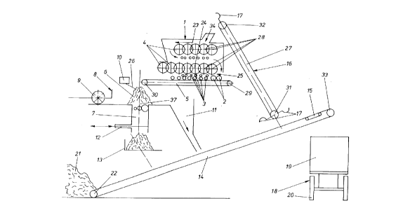
FIG. 1 is a schematic representation of a device for
carrying out the method according to the invention;
FIG. 2 shows an enlarged front view of a screen star
of the screening plant contained in the device according to FIG. l;
and
FIG. 3 shows a schematic front view of a detail of the
screening plant with screen stars shown by sectional views.
DETAILED DESCRIPTION OF THE PREFERRED EMBODIMENT
Referring now in detail to the drawings and, in
particular, FIG. 1, there is shown a schematic representation of a
device according to the invention for determining delivered volume
of a lot of bulk material such as, for example auxiliary soil
materials and culture substrates. The device has a loading device
for the gradual collection and loading of the lot, which is
designed in the form of a loading belt 14. Loading belt 14 starts
with its end 22 on the receiving side at a storage site 21 of the
lot and ends with its end 33 at the discharging side at a loading
site shown as truck 18. Truck 18, which is realized as the,loading
site, has an undercarriage 20 and a loading area in the form of
container 19. A conveyor belt scale 15 continuously records the
-- 19 --
CA 022186~2 1997-10-20
weight of the portion of the lot being loaded and is arranged
within the zone of end 33 of transporting belt 14 on the discharge
side.
A sample collection device 16 consists of an endless
conveyor 27, which is equipped with revolving, radially projecting
buckets 17. The length of the path of conveyance of endless
conveyor 27 is limited by the lower reversing roller 31 as the
collection zone, and the upper reversing roller 32 as the
discharging zone. The lower reversing roller 31 is arranged with
the collection zone of endless conveyor 27 within the range of the
transport path determined by loading belt 14 for conveying the lot
gradually collected at the storage site to the loading site.
Buckets 17 revolving on the lower reversing roller 31
are tangent to loading belt 14 in such a way that they collect
samples from the gradually collected portion of the lot to be
shipped as they are conveyed along loa,ding belt 14. The samples
picked up by buckets 17 are ejected into a screening plant
through an inlet 34 of screening plant 1. Buckets 17 are emptied
as the upper reversing roller 32 is rotating. In the present case,
screening plant 1 has an upper screening plane 23 and a lower
screening plane 24.
-- 20 --
CA 022186~2 1997-10-20
Each of screening planes 23 and Z4 are formed by shafts
28 arranged in parallel. Several screen stars 4 are mounted on
each rotating shaft 28. The stars are indicated here as circles,
but shown in greater detail in FIG. 2. Each screen star is
equipped with screening star arms 35, 35', and 35~, which project
radially with respect to shaft 28, as shown in FIG. 3. The overlap
zone 38 (not shown here) of star arms 35, 35' and 35~ of screen
stars 4 of adjacent shafts 28 determines the grain fraction of each
screening plane 23 and 24 to be screened. Overlap zone 38 of star
arms 35 is selectable by the dimension of star screens 4 and by the
spacing of shafts 28.
The route of transport of the overgrain of the samples
is indicated by arrows shown in screening plant 1. Overgrain 2 is
ejected on ejection side 25, and the screened grain fractions 3 are
ejected onto the transporting belt 5 arranged below screening plant
1. Transporting belt 5 extends across ejection side 25 of
screening plant 1, whereby the length of transporting belt 5 is
limited by a first reversing roller 29 and a second reversing
roller 30 arranged within the zone of inlet side 37 of a measuring
container 7.
Measuring container 7 has a predetermined volume and
its bottom is designed in the form of a slide 12. When measuring
- 21 -
CA 022186~2 1997-10-20
container 7 is filled, a pouring cone 6 forms at the edge of the
opening of measuring container 7. The filling process for filling
measuring container 7 is controlled by a filling level sensor 10
that senses the height of the pouring cone projecting beyond the
edge of the opening of measuring container 7. Filling level sensor
10 has a scanning device 26 scanning the height. Filling level
sensor 10 is coupled with the drive of screening plant 1 and the
drive of transport belt 5, so that when the predetermined volume of
measuring container 7 is reached, screening plant 1 and/or
transport belt 5 can be switched off.
A scraping device 8, which is coupled with filling
level sensor 10, is arranged at the edge of the opening of
measuring container 7 on inlet side 37 of the measuring container.
Scraping device 8 has a scraping element in the form of a rotating
cutter 9 for scraping off the projecting part of pouring cone 6 in
a plane corresponding with the filling level of the measuring
container after a predetermined volume of the filling of said
container has been reached. The portion of pouring cone 6 cut off
by cutter 9 is returned via a funnel-like collection device 11 to
loading belt 14 by simply dropping onto the latter, and is thus
added again to the lot.
- 22 -
-
CA 022186~2 1997-10-20
By actuating slide 12 on the bottom side of measuring
container 7, the contents of measuring container 7 can be loaded on
an electronic scale 13 arranged beneath measuring container 7.
Electronic scale 13 determines the weight of the content of
measuring container 7. The weighed content of measuring container
7 can be tilted onto loading belt 14 by a tilting motion of scale
13. Electronic scale 13 is connected to a data processing facility
(not shown). Such data processing facility can record the net
weight of the content of measuring container 7 as determined in
each case by scale 13, and store same in a recallable way. The net
weight of the content of measuring container 7 is divided by the
predetermined volume of measuring container 7. The bulk density of
the contents of measuring container 7 follows from such division.
Also, a mean bulk density can be determined when several measuring
containers 7 are filled with screened samples of lot. Conveyer
belt scale 15, which continuously records the weight of the part of
the lot being loaded, is connected to the data processing facility
as well, so that the delivered volume of the lot follows from the
recorded total weight of the lot divided by the mean bulk density
of the content of measuring container 7.
FIG. 2 shows an enlarged front view of screen star 4
of screening plant 1. Screen star 4 has star arms 35 projecting
across its circumference. A hub 36 fitting on shaft 28 is located
CA 022186~2 1997-10-20
in the center of the screen star.
FIG. 3 shows two adjacent shafts 28 of a screening
plane 23 or 24 with the screen stars 4, 4' and 4" arranged thereon.
Screen stars 4, 4' and 4" each are torsionally rigidly mounted on
shafts 28 with their hubs 36, 36' and 36", respectively. Overlap
zone 38 of screen arms 35, 35' and 35" is selectable by the
dimension of screen stars 4, 4', and 4", and by the spacing of
shafts Z8. The size of overlap zone 38 of star arms 35, 35' and
35" determines the screenable grain fraction because the grain
fractions to be screened are loosened in overlap zones 38 by the
screen stars 4 rotating on shafts 28, and thereby screened.
Accordingly, while only one embodiment of the present
invention has been shown and described, it is obvious that many
changes and modifications may be made thereunto without departing
from the spirit and scope of the invention.
- 24 -