Note: Descriptions are shown in the official language in which they were submitted.
CA 02218791 1997-10-21
COMPOSITE PACKAGE STRUCTURE FOR CONTAINING
ARTICLES AND METHOD FOR PRODUCING THEREOF
BACKGROUND OF THE INVENTION
Field of the Invention
This invention relates to paperboard and plastic
composite package structures that combine an intricate
thermoformed shell with a paperboard base or cover. Such
structures of this type, generally, provide a lightweight
package with a good printing surface on the outside of the
package.
Description of the Related Art
It is known, in composite package structures, to make
use of a book-like container paperboard cover and a plastic
inner tray. Exemplary of such structures is U.S. Patent
No. 4,724,957 ('957), to 0. Burgschweiger, entitled
"Container." While the '957 patent teaches a paperboard
cover and a plastic inner gray, the cover is not connected
to the inner tray along the spine. Also, foil is located
1
CA 02218791 1997-10-21
on the exterior side of the cover. It is apparent, that if
the inner tray were bonded to the paperboard cover along
the length of the spine, greater package rigidity would
result. Also, if the foil cover were eliminated, a wider
range of printed graphics could be used. Consequently, a
more advantageous container, then, would be presented if
the rigidity and range of printed graphics were increased.
It is also known, in composite packages, to make use
of an inner molded tray and an outer cover. Exemplary of
such prior art is U.S. Patent No. 4,635,797 ('797) to J. D.
Bankier, entitled "Pilfer Resistant Software Package."
While the '797 patent teaches the use of a composite
paperboard and plastic package, the plastic inner tray is
welded to the paperboard cover by conventional RF
techniques along the peripheral flange. The use of the
high temperature RF techniques may cause temperature
deformation of the thermoformable inner tray.
Consequently, a still further advantageous composite
package, then, would be presented if a low temperature,
heat sealable coating were used.
Finally, it is known, in composite package structures,
to make use of a plastic case suitable for housing objects.
Exemplary of such prior art is U. S. Patent No. 5,353,932
2
CA 02218791 1997-10-21
('932) to K. Kollinek, entitled "Video Case and Method of
Manufacturing." While the '932 reference teaches the use of
a thermoformed plastic inner liner, a cardboard stiffener,
an outer vinyl cover, a paper sleeve, and an outer clear
plastic cover, the stiffener is not heat sealable which
requires the extra outer covers and the added production
expense. Also, the method of manufacture as disclosed in
the '932 reference requires many production passes, i.e.,
a transportation of the intermediate product from one
machine to another until the complete video case is
constructed. Finally, because the various components of
the '932 reference are individually cut and then added
together to construct the final product, differences in
thermal expansion ,between the dissimilar materials may
cause an uneven and unattractive alignment between various
components. Therefore, an even further advantageous
composite package, then, would be presented if a heat-
sealable paperboard could be used in conjunction with fewer
and more efficient production steps.
It is apparent from the above that there exists a need
in the art for a composite package which is rigid and is
capable of employing a wide range of printed graphics and
which at the same time avoids the use of high temperatures,
3
CA 02218791 1997-10-21
but which employs a sealable paperboard and in conjunction
with fewer and efficient production steps. It is a purpose
of this invention to fulfill this and other . needs in ,the
art in a manner more apparent to the skilled artisan once
given the following disclosure.
SUN~IARY OF THE INVENTION
Generally speaking, this invention fulfills these
needs by providing a composite package for containing
articles, comprising a paperboard base having first and
second sides, a layer of particulate minerals located
exterior to the first side of the paperboard base, a layer
of a low temperature, heat sealable polymeric material
located exterior to the second side of the paperboard base
wherein the polymeric material is further comprised of a
water-based ethylene vinyl acetate, a printed graphics
located exterior to the layer of particulate minerals, a
layer of varnish located exterior to the layer of printed
graphics, and a thermoformable polymeric shell having first
and second sides such that the first side of the shell is
rigidly attached to the heat sealable polymeric material
and the second side includes a plurality of article holding
means and a flexible spine means located substantially
4
CA 02218791 1997-10-21
between the plurality of the article holding means such
that the plurality of articles holding means provide 'a
means for holding an article when the article holding means
are closed and the spine means provides support for the
composite package and an alignment means for the article
holding means.
In certain preferred embodiments, the particulate
minerals are clay. Also, the thermoformable shell is
constructed of polyvinyl chloride or a similar plastic
material. Finally, the varnish is an electron-beam curable
varnish.
In another further preferred embodiment, the composite
package structure provides a lightweight package with a
good printing surface on the outside of the package.
The preferred composite package, according to this
invention, offers the following advantages: lightness in
weight; use of a wider range of printed graphics; increased
rigidity; lower manufacturing temperatures; good stability;
good durability; increased scuff resistance; increased
moisture resistance; and good economy. In fact, in many of
the preferred embodiments, these factors of lightness in
weight, a wider range of graphics, increased rigidity, and
lower temperatures are optimized to the extent that- is
CA 02218791 1997-10-21
considerably higher than heretofore achieved in prior,
known composite packages.
The above and other features of the present invention,
which will become more apparent as the description
proceeds, are best understood by considering the following
detailed description in conjunction with the accompanying
drawings, wherein like characters represent like parts
throughout the several views and in which:
BRIEF DESCRIPTION OF THE DRAWINGS
FIGURE 1 is a schematic illustration of a method for
producing a composite package, according to the present
invention;
FIGURE 2 is a side, exploded view the composite
package, according to the present invention;
FIGURE 3 is a cross-sectional view of a composite
cover, according to the present invention; and
FIGURE 4 is a side view of the constructed composite
package of FIGURE 2 and folded, according to the present
invention.
6
CA 02218791 1997-10-21
DETAILED DESCRIPTION OF THE INVENTION
With reference first to Figure 1, there is illustrated
a system 2 for manufacturing a composite package 22. In
particular, system 2 includes in part, thermoformable
polymer roll 4, thermoformable polymer sheet 6,
conventional thermoformer 8, thermoformed polymer trays 10,
flexible spine 11, conventional magazine 12, paperboard
covers 14, heat sealer/trimmer 16, and composite packages
22. Thermoformable polymer roll 4 and sheet 6, preferably,
are constructed of polyvinyl chloride (PVC), polystyrene,
polyethylene terephthalate (PET) or any plastic material
which can be thermoformed to create an inner tray shaped to
match the product of interest.
As more clearly shown in Figure 3, paperboard covers
14, preferably, include a paperboard base 30, a coating 32
of particulate minerals on one side, a layer 33 of printed
graphics, a coating 34 of a conventional, electron-beam
curable varnish and a coating 24 of a low temperature, heat
sealable polymeric material on the other side. The
particulate minerals, preferably, are clay. The low
temperature, heat sealable polymeric material, preferably,
is a water-based ethylene vinyl acetate (EVA) produced by
Pierce & Stevens, Inc. of Buffalo, New York under the
7
CA 02218791 1997-10-21
tradename Latiseal~. The polymeric material is applied at
a coat weight of 6.6-19.8 kg/278.7 m2 (3-9 pounds/3000
ft.2) . Preferably, the coat weight is 1 3.2 kg/278.7 m2 (6
pounds/3000 ft.2). It is to be understood that coating 34
can be applied to cover 14 by a conventional in line
process in combination with printing and electron-beam
curing of the printing. It is to be understood that
coating 24 and layer 33 can be applied to cover 14 by
conventional techniques.
During the construction of composite packages 22, roll
4 is unrolled such that sheet 6 is formed. Sheet 6 is
transferred through thermoformer 8 such that a web of trays
having flexible spine 11 is produced. After the web of
trays 10 is produced, a paperboard cover 14 is placed upon
one side of trays 10 such that coating 24 (Figure 2) is
adjacent to tray 10. Cover 14,-preferably, has been
printed with graphics layer 33 and coated with the varnish
and cured with a conventional electron beam, such that as
the electric beam contacts coating 34 a cross-linking
between the various components in coating 34 is achieved
which improves moisture resistance and scuff resistance and
durability of coating 34.
8
i
CA 02218791 2002-O1-25
i
After the paperboard cover 14 is placed upon tray 10,
tray 10 and cover 14 are heat sealed and trimmed in heat
sealer/trimmer 16 such that composite packages 22 are
produced. It is to be understood that heat sealer 16
employs a conventional platen heat sealer which contacts
coating 34 such that ~an adhesion between the various
components in coating 29; and tray 10 is achieved.
It is also to be understood that the construction of
composite package 22 is achieved in one-pass, i.e., package
22 is not transferred from one production line to another
in order to construct package 22. Also, due to the set-up
of the construction of package 22, cover 14 and tray 10 are
heat sealed and then trimmed, although in a relatively
short time period. In this manner, any differences in the
coefficient of thermal expansion between the dissimilar
elements and their possible resulting misalignment should
be taken care of by the subsequent trimming. Thus, the
heat sealing and subsequent trimming creates a clean and
matched edge which should be resistant to any bending or
fraying which is commonly referred to as "dog-earring."
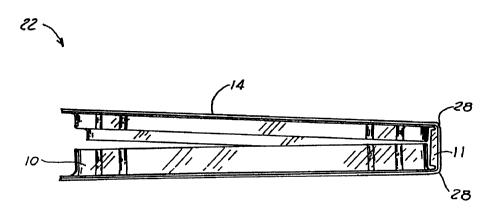
Figures 2 and 4 illustrate, in more detail, the final
construction of composite package 22. In particular,
composite package 22 includes, in part, thermoformed
9
CA 02218791 1997-10-21
polymer tray 10, flexible spine 1 1 , paperboard cover 1 4,
low temperature, heat sealable coating 24, flange 26, score
lines 28, paperboard base 30, particulate coating 32,
printed graphics layer 33 and varnish layer 34. Coating
24, preferably, is the same low temperature, heat sealable
coating 24, as described above. Also, coatings 32, 33 and
34 are the same coatings 32, 33 and 34 as described above.
Also, score lines 28 are placed on paperboard cover 14 in
order to provide a desired flexibility within paperboard
cover 14. It is to understood, however, that score lines
28 may be omitted in certain instances.
In order to secure articles within package 22, package
22 is oriented such that the articles are placed in one
section of tray 10 as shown in Figure 4. The other section
of tray 10 is then folded over in a book-like manner, along
score lines 28 and coupled with the section of tray 10
holding the articles. In this manner, the articles are
retained within tray 10 and package 22. Finally, flexible
spine 11 is employed to add structural rigidity to package
22 and provide an alignment means so that the separate
sections of tray 10, which are used to hold articles, can
be properly aligned.
CA 02218791 1997-10-21
Once given the above disclosure, many other features,
modifications or improvements will become apparent to the
skilled artisan. Such features, modifications or
improvements are, therefore, considered to be a part of
this invention, the scope of which is to be determined by
the following claims.
11