Note: Descriptions are shown in the official language in which they were submitted.
96P7567 CA 02218833 1997-10-22
IONIZATION CHAMBER HAVING
OFF-PASSAGEWAY MEASURING ELECTRODES
BACKGROUND OF THE INVENTION
The invention relates generally to monitoring a radiation beam, and
more particularly to an ionization chamber for monitoring beam characteristics
of radiation emitted from a linear accelerator.
DESCRIPTION OF THE RELATED ART
Systems for emitting a high-energy radiation beam are known and are
used in such applications as providing radiation therapy. For example, a
linear accelerator emits a radiation cone that may be an electron beam or a
photon tx-ray) beam. When used to provide radiation therapy, the emitted
beam is then configured to substantially match the shape of diseased tissue,
with a goal of minimizing any adverse effect upon adjacent healthy tissue.
The linear accelerator may be located in a gantry that rotates relative to a
movable table on which a patient is supported.
In radiation therapy, an emitted cone of radiation should have a
uniform dose rate and intensity across the entire cross section of the cone.
Flattening filters within a primary collimator are sometimes used to achieve
this uniformity. Nevertheless, it is common to use an ionization chamber to
analyze the homogeneity of the beam, whether the beam is conical or
cylindrical. U.S. Pat. No. 4,627,089 to Menor et al., which is assigned to the
assignee of the present invention, describes a linear accelerator system
25 having a flattening filter and a dose chamber for monitoring the characteristics
of the radiation cone. In many applications, the system includes two
ionization chambers, with the first chamber used when an electron beam is
monitored and with the second chamber moved into the position of the first
when the system is used to apply an x-ray beam. Typically, the ionization
30 chamber or chambers will be connected to corrective circuitry for providing
beam adjustment, if needed.
U.S. Pat. No. 4,131,799 to Stieber describes an ionization chamber for
analyzing inhomogeneities in a radiating beam from a particle accelerator
96P7567 CA 02218833 1997-10-22
system. The ionization chamber includes two measuring chambers formed
by three mutually parallel walls that are spaced apart by spacer rings. Two of
the three parallel walls have single electrodes formed on the wall surfaces,
while a third wall has several mutually isolated electrodes that include a
5 central circular electrode and a group of electrode segments arranged in
circular fashion around the central electrode. Inhomogeneities in the
radiation intensity of a beam are detected by comparing currents in the
central electrode relative to the surrounding electrode segments or in the
electrode segments themselves relative to each other.
U.S. Pat. No. 5,326,967 to Kikuchi describes an ionization chamber
that forms an ionization space using a frame made of insulating material. A
high-voltage electrode and a collecting electrode are positioned on opposite
sides of the ionization space to cause an ionization current when a radiation
beam is projected through the frame. The ionization space has an equal
15 dimension throughout the passage of the radiation, so that Boyle-Charles'
Law applies to the ionization space. The ionization chamber is airtight.
- Sealed ionization chambers are common in the art.
Other ionization chambers and circuitry for providing beam correction
are described in U.S. Pat. Nos. 5,072,123 to Johnsen, 4,751,393 to Corey, Jr.
20 et al., 4,206,355 to Boux, and 3,852,610 to Mclntyre. While the other three
patents are for use in radiotherapy systems, Corey, Jr. et al. describes a
system for ion implantation, such as used in semiconductor wafer fabrication,
in which the radiation beam is continuously scanned. In this scanning
implementation, beam-sensing apertures are positioned adjacent to the
25 aperture for passage of the scanning ion beam to the target plane. While
there are a number of beam-sensing apertures, a single beam current signal
is generated, with a demultiplexing scheme then being used to separate the
individual signals of the beam-sensing apertures. The demultiplexing scheme
utilizes the scanning signal to identify the individual beam-current
30 components of the single signal. Many of the features of Corey, Jr. et al. are
not applicable to the fixed-beam implementations of the above-cited patents.
In addition to monitoring beam homogeneities, ionization chambers
monitor beam position and direction. Proper patient treatment requires
96P7567 CA 02218833 1997-10-22
precise application of the radiation beam to diseased tissue. Comparison of
the signals from different electrodes contained within an ionization chamber
allows the system to determine beam position and directionality.
While the prior art ionization chambers and beam-monitoring systems
5 operate well for their intended purposes, the ionization chambers are often
cost ineffective. For example, if separate ionization chambers are needed for
monitoring an electron beam and an x-ray beam, there must be a duplication
of parts. Moreover, the ionization chambers are often sealed, so that the
airtight chambers are less susceptible to the influence of variations in air
10 pressure and/or temperature. Providing an airtight seal increases the cost of manufacture.
What is needed is an ionization chamber that monitors radiation beam
characteristics and position in a reliable and cost-effective manner, with a
single ionization chamber being suitable for monitoring both electron and
15 photon beam energy.
SUMMARY OF THE INVENTION
An ionization chamber for monitoring a radiation beam includes a
housing having a primary beam passageway and having an array of
20 secondary beam cells adjacent to the primary beam passageway. A first
array of beam measuring electrodes is contained within the housing and
located along the primary beam passageway. These first beam measuring
electrodes have outputs that are responsive to detection of energy of that
portion of a radiation beam that is directed through the primary beam
25 passageway. Second beam measuring electrodes are located within the
secondary beam cells and have outputs responsive to energy of a second
portion of the radiation beam. In the preferred embodiment, there is also a
large-area beam measuring electrode that is positioned within the primary
beam passageway and that has an area exceeding the sum of the areas of
30 the first beam measuring electrodes. High voltage electrodes are disposed
relative to the beam measuring electrodes to induce ionization current that is
used to detect radiation characteristics, direction and position.
In another embodiment, the second beam measuring electrodes are
96P7567 CA 02218833 1997-10-22
arranged parallel to the large-area beam measuring electrode and are
symmetrically arranged immediately about the axis of the primary beam
passageway. This arrangement of the second beam measuring electrodes at
the axis increases the sensitivity of the ionization chamber to beam tilt and
5 misalignment. The ionization chamber can be used to measure either
electron or photon radiation and, in one embodiment, is pervious to the
surrounding atmosphere. Temperature sensors may be connected to an
unsealed ionization chamber, so that processing circuitry can be used to
offset changes in monitoring data with variations in temperature.
BRIEF DESCRIPTION OF THE DRAWINGS
Fig. 1 is a side view of a radiation system having an ionization chamber
in accordance with the invention.
Fig. 2 is a side sectional view of the ionization chamber of Fig. 1.
Fig. 3 is a conceptual view of the arrangement and operation of beam
measuring electrodes of Fig. 2.
Fig. 4 is a top view of a lower ring film of Fig. 2, with a conductive layer
that forms an array of beam measuring electrodes.
20 BEST MODE FOR CARRYING OUT THE INVENTION
With reference to Fig. 1, a radiation system for medical applications is
shown as including a conventional linear accelerator 10 which generates an
electron beam 12 that is accelerated using known energy-transfer techniques.
A guide magnet 14 bends the electron beam by approximately 270~. The
25 electron beam then exits through a window 16 that is transparent to the
beam, but preserves the vacuum condition within the linear accelerator and
guide magnet. The window may be formed of titanium, but this is not critical.
Photon radiation is produced by impinging the emitted electron beam
with a target 18. Alternatively, a scattering foil may be utilized, if electron
30 radiation is desired. Whether a target is used in order to provide photon
radiation or a scattering foil is used, a conical beam is formed.
The exemplary radiation system of Fig. 1 is shown as including a
beamstopper 20. Beamstoppers are known in the art, but are not critical to
- 96P7567 CA 02218833 1997-10-22
the invention. The conical radiation beam enters a primary collimator 22
having a stepped interior 24. The primary collimator provides an initial
limitation on the expansion of the conical radiation beam.
Within the stepped interior 24 of the primary collimator is a stainless
5 steel flattening filter 26. A flattening filter "flattens" the energy spectrum of a
conical x-ray beam. The flattening filter has a conical design that is contouredto achieve desired beam characteristics, e.g., beam homogeneity. The
flattening filter 26 is a low energy type, e.g., 6 MV. When the radiation
system is in a higher energy mode, e.g.10 MV, the primary collimator 22 is
10 shifted so that a second stepped interior 28 is aligned with the exit window 16
of the guide magnet 14. Within the second stepped interior is a higher energy
flattening filter 30. A 10 MV absorber 32 is at the entrance of the second
stepped interior 28, while a compensator 34 is located at the exit. The
functions of the absorber and the compensator are well known in the art.
An ionization chamber 36 is utilized to monitor beam characteristics,
alignment and directionality. The structure and operation of the ionization
chamber will be described fully below.
A mirror 38 is employed in the setup procedure of the radiation system.
Prior to application of the radiation beam onto a patient, a light source is
20 directed at the mirror to project a light field onto the patient. If the light field
does not match the desired radiation field, beam-defining structure is
manipulated until a light field-to-radiation field coincidence is achieved. In
Fig. 1, the field-defining structure is a secondary collimator having Y-axis jaws
and X-axis jaws. The X-axis jaws are shown as including two blocks 40 and
25 42 formed of radiation attenuating material. Likewise, the Y-axis jaws include
two blocks, but only one of the blocks 44 is visible in Fig. 1. The blocks are
movable relative to each other, allowing a beam passing through the
secondary collimator to be trimmed and shaped. More intricate beam
configurations are possible using multi leaf collimators.
Also shown in Fig.1 are a wedge tray 46 and a wedge filter 48. A
wedge filter is a tapered block of radiation material that is used to provide a
progressive decrease in the dose rate across a portion or all of a treatment
region of a patient 50.
96P7567 CA 02218833 1997-10-22
With the exception of the ionization chamber 36, none of the structure
of Fig. 1 is critical to the invention. A side sectional view of the ionization
chamber is shown in Fig. 2. The ionization chamber is used to monitor either
an electron radiation beam or a photon radiation beam. That is, rather than
5 having separate ionization chambers for the two forms of energy, a single
chamber operates in both capacities. This reduces the manufacturing cost of
the overall radiation system.
The ionization chamber is pervious to the surrounding atmosphere.
Consequently, less expensive materials and manufacturing processes may
10 be used in forming the ionization chamber, relative to conventional sealed
chambers. In order to compensate for any changes in the temperature during
beam monitoring, a temperature sensor 52 is included. The temperature
sensor may be a thermistor that is connected to data processing circuitry. If
the temperature of the ionization chamber 36 varies, the sensor will detect the
15 variation. The processing circuitry may have stored memory (e.g., a look-up
table) of the effect of beam measurements with changes in temperature. This
~ allows the processing circuitry to offset such effects. In the preferred
embodiment, there are multiple temperature sensors.
The most significant difference between the ionization chamber 36 of
20 Fig. 2 and conventional ionization chambers for radiation beam monitoring
relates to the arrangement of beam measuring electrodes. This arrangement
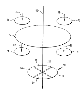
is shown conceptua!ly in Fig. 3. A total of nine beam measuring electrodes is
utilized, but this number is not critical to the invention. The electrodes include
a large-area beam measuring electrode 54 that is coaxial with the radiation
25 beam when the radiation beam is properly aligned. The beam axis 56 is
shown in Fig. 3. In addition to the large-area electrode 54, an array 58 of
small-area beam measuring electrodes 60, 62, 64 and 66 is coaxial with the
radiation beam. In the preferred embodiment, the small-area electrodes are
electrically isolated segments of a patterned conductive layer, with each
30 segment being immediately adjacent to the axis defined by the large-area
electrode 54.
In addition to the on-axis beam measuring electrodes 54, 60, 62, 64
and 66, there are four off-axis beam measuring electrodes 68, 70, 72 and 74.
96P7567 CA 02218833 1997-10-22
As will be explained more fully below, the off-axis electrodes are beyond the
beam passageway through the ionization chamber 36 of Fig. 2. The off-axis
electrodes are impinged by beam portions 76, 78, 80 and 82 that do not
contribute to treatment of a patient, since the beam portions do not exit the
5 ionization beam. As a result, the use of the off-axis electrodes does not
contaminate the treatment beam. The size of the off-axis electrodes can,
therefore, be larger than conventionally positioned beam measuring
electrodes that are used for comparable purposes.
The electrode arrangement shown conceptually in Fig. 3 may be
10 utilized in a variety of signal processing implementations. In the preferred
embodiment, the large-area beam measuring electrode 54 is used in
connection with the array 58 of small-area electrodes 60, 62, 64 and 66 to
provide dual channel capability. Safety standards sometimes require
redundant channels for the determination of whether a radiation beam is
15 being propagated through the ionization chamber. The large-area beam
measuring electrode 54 preferably has a diameter that is generally equal to
the diameter of the primary beam passageway through the ionization
chamber 36. Consequently, any effect of the electrode on the propagating
radiation beam will be uniform. The array 58 of electrodes 60, 62, 64 and 66
20 has a total area that is substantially less than the area of the electrode 54.
The dimensions of the array 58 are not accurately shown in Fig. 3. In the
preferred embodiment, the array 58 has a total area only slightly greater than
the area of one of the off-axis electrodes 68, 70, 72 and 74. The small array
provides the required beam monitoring data with a minimal effect on the
25 beam.
The axially located small-area electrodes 60, 62, 64 and 66 are well
suited for detecting beam tilt and misalignment. The proximity of each of the
electrodes of the array to the desired beam axis 56 increases the sensitivity ofthe array to variations in beam flatness and symmetry.
As previously noted, the off-axis beam measuring electrodes 68, 70,
72 and 74 are "off-passageway." That is, the electrodes are outside of the
primary beam passageway through the ionization chamber 36. Since the size
of the electrodes will not adversely affect the treatment beam, these
96P7567 CA 02218833 1997-10-22
electrodes may be substantially larger than conventionally located electrodes
and will consequently provide a high signal-to-noise ratio (SNR) with regard to
both in-plane and cross-plane information. Such information is particularly
useful for purposes of beam steering.
In one embodiment, the diameter of the primary beam passageway
through the ionization chamber 36 is 6.4 cm, and the diameter of the large-
area beam electrode 54 is only slightly less than 6.4 cm in order to be isolatedfrom the metallic rings to be described below. The diameter of the array 58
may be 2.05 cm, and the diameter of each of the off-axis beam measuring
electrodes 68, 70, 72 and 74 may be 1.6 cm. However, these dimensions are
not critical to the invention.
The ionization chamber 36 of Fig. 2 is formed of six rings, with five of
the rings having a film adhered to the ring. Although not critical, the films are
preferably formed of an insulative material sold by DuPont Company under
15 the federally registered trademark KAPTON. A top cover ring 84 is an
annular member that includes an axial opening that forms the first portion of
the primary beam passageway 86 through the ionization chamber. In
addition, the top cover ring includes four symmetrically arranged openings
that form the first portions of four secondary beam cells 88 and 90, only two
20 of which are shown Zn Fig. 2. The insulative film 92 that is adhered to the top
cover ring 84 may have a thickness of 0.3 cm.
Immediately below the top cover ring 84 is a top ring 94 that
structurally is substantially identical to the top cover ring. Thus, the four
secondary beam cells 88 and 90 extend through the top ring. The film 96 that
25 is adhered to the top ring may have a thickness of approximately 0.15 cm. A
patterned layer of conductive material is formed on the underside of the film
96. For example, gold may be deposited to a thickness of 50 nm and/or
electroplated to a thickness of 200 nm. Conventional etching techniques may
then be used to remove portions of the gold layer from the surface of the
30 KAPTON film 96. The resulting patterned film leaves the large-area beam
measuring electrode 54 and the four off-axis beam measuring electrodes 68,
70, 72 and 74 of Fig. 3.
A middle ring 98 is the last ring through which the secondary beam
96P7567 CA 02218833 1997-10-22
cells 88 and 90 extend. A KAPTON film 100 of approximately 0.15 cm has a
patterned middle layer on each of the opposed major sides. On the upper
major side, an electroplated gold layer of approximately 200 nm thickness is
patterned to provide an arrangement of high voltage electrodes 102,104 and
5 106 that substantially matches the beam measuring electrodes on film 96.
Only two of the high voltage electrodes 104 and 106 for the off-axis beam
measuring electrodes 68, 70, 72 and 74 are shown in Fig. 2, but in the
preferred embodiment there is a one-to-one correspondence of the off-axis
high voltage electrodes and the off-axis beam measuring electrodes of Fig. 3.
10 Electrical connections to the various electrodes can be achieved using any ofknown techniques. For example, the electrical connections may be from the
bottom of the ionization chamber 36, such as shown with the temperature
sensor 52. The central high voltage electrode 102 on the upper surface of
the middle ring film 100 is operatively associated with the large-area beam
15 measuring electrode 54. All of the high voltage electrodes may be connected
to a source of 600 volts, but the voltage is not critical to the invention.
~ On the underside of the middle ring film 100 is a patterned high voltage
electrode 108 that is formed of a patterned gold layer. An acceptable layer is
an electroplated gold layer having a thickness of approximately 200 nm.
20 While not critical, the high voltage electrode 108 may have a diameterthat isapproximately equal to the diameter of the array 58 of small-area electrodes
60, 62, 64 and 66.
Below the middle ring 98 is an annular spacer 110. The spacer is the
only ring component of the ionization chamber 36 that is not adhered to a
25 film. In comparison, a lower ring 112 has an attached film 114 that supports
the array 58 of small-area beam measuring electrodes directly below the high
voltage electrode 108. A top view of the film 114 is shown in Fig. 4. A layer
of electroplated gold is patterned to form the four small-area electrodes 60,
62, 64 and 66 and to form leads 116, 118, 120 and 122 for conducting signals
30 from the electrodes to outside circuitry. The electrodes of the film are spaced
apart by an insulative region 124. While not shown, the preferred
embodiment includes metallization at the exterior region 126. This metallized
exterior region is electrically grounded during operation. Therefore, the
96P7567 CA 02218833 1997-10-22
electrodes and leads must be isolated from the grounded exterior region.
At the bottom of the ionization chamber 36 of Fig. 2 are a lower cover
ring 128 and a film 130. The thickness of the film may be 0.3 cm, but the
thickness is not critical to the invention. The films 92 and 130 that are
5 attached to the cover rings 84 and 128 are the only two films without
metallization. Each of the rings 84, 94, 98, 110,112 and 128 may be formed
of aluminum. While not shown, fastening members pass through each of the
rings in order to fix the assembly in position. Through holes 132 are shown in
the film 114 of Fig. 4. The fastening members pass through the holes 132
10 and through aligned holes of the other components of Fig. 2.
In operation, the physics of beam measurement is well known in the
art. When a radiation beam is propagated through the primary beam
passageway 86 and simultaneously into the secondary beam cells 88 and 90,
ions are produced in the gas within the ionization chamber 36. For example,
15 between the large-area beam measuring electrode 54 and the high voltage
electrode 102 is a measuring chamber in which ions will be produced.
Because of the potential difference and polarity orientation between the high
voltage electrode and the large-beam measuring electrode, an ionization
current is generated. This current is directly proportional to the radiation
20 intensity in the measuring chamber. The signal from the beam measuring
electrode 54 will correspond to the ionization current. A second measuring
chamber 136 is formed between the array 58 and the high voltage electrode
108. The second measuring chamber 136 is a segmented chamber, since
the array comprises four beam measuring electrodes 60, 62, 64 and 66 as
25 shown in Figs. 3 and 4. As with the first measuring chamber 134, the signals
from the beam measuring electrodes will be indicative of the ionization current
generated as a result of the potential difference and polarity orientation of the
individual electrodes relative to the high voltage electrode. However, for the
segmented second measuring chamber 136, the individual signals from the
30 electrodes may be used to monitor beam symmetry and homogeneity. In the
ideal, the beam has a uniform intensity in its cross section and is coaxial withthe ionization chamber 36. In this ideal situation, the signals from the four
small-area beam measuring electrodes will be identical.
96P7567 CA 02218833 1997-10-22
.
11
Measuring chambers are also formed within the secondary beam cells
88 and 90. The high voltage electrodes 104 and 106 within the secondary
beam cells operate to provide the ionization current for generating beam
measuring signals from the off-axis electrodes 68, 70, 72 and 74. As
5 previously noted, these signals may be used in any of a number of
implementations to acquire information regarding the radiation beam.
Because the off-axis electrodes are preferably significantly larger than the
individual beam measuring electrodes 60, 62, 64 and 66 of the array 58, the
signals will tend to be strong. The off-axis electrodes may be particularly
10 useful in acquiring in-plane and cross-plane information for use in properly
steering the radiation beam.
While the invention has been described and illustrated as having four
off-axis electrodes and four small-area beam measuring electrodes, this is not
critical. The number may vary depending upon the application. In fact, in
15 some embodiments it may be preferable to eliminate the secondary beam
cells 88 and 90, while continuing to utilize the advantages of having the large-
- area beam measuring electrodes in conjunction with the array 58 of small-
area beam measuring electrodes.