Note: Descriptions are shown in the official language in which they were submitted.
CA 02218899 1997-11-12
WO 96/40322 PCT~US96/10212
EXTEU~CORPO~E~LL BI~DD P~OrP~ING
~ T~OD8 A~DD APPA~U~TU8
FIELD OF THE l~v~NllON
The present invention generally relates to the field
of extracorporeal blood processing and, more particularly,
to methods and apparatus which may be incorporated into an
apheresis system (e.g., blood component collection,
therapeutic).
BACKGROUND OF THE lNv~:N~ oN
One type of extracorporeal blood processing is an
apheresis procedure in which blood is removed from a donor
or patient, directed to a blood component separation device
(e.g., centrifuge), and separated into various blood
component types (e.g., red blood cells, white blood cells,
platelets, plasma) for collection or therapeutic purposes.
One or more of these blood component types are collected
(e.g., for therapeutic purposes), while the remainder are
returned to the donor or patient.
A number of factors affect the commercial viability of
an apheresis system. one factor relates to the operator of
the system, specifically the time and~or expertise required
of an individual to prepare and operate the apheresis
system. For instance, reducing the time required by the
operator to load and u~load the disposables, as well as the
complexity of these actions, can increase productivity
and/or reduce the potential for operator error. Moreover,
reducing the dependency of the system on the operator may
lead to reductions in operator errors and/or to reductions
CA 02218899 1997-11-12
W O 96/40322 PCTrUS96/10212
-- 2
in the credentials desired/required for the operators of
these systems.
Donor-related factors may also impact the commercial
viability of an apheresis system and include donor
convenience and donor comfort. For instance, donors
typically have only a certain amount of time which may be
committed to visiting a blood component collection facility
for a donation. Consequently, once at the collection
facility the amount of the donor's time which is actually
spent collecting blood components is another factor which
should be considered. This also relates to donor comfort
in that many view the actual collection procedure as being
somewhat discomforting in that at least one and sometimes
two access needles are in the donor throughout the
procedure.
Performance-related factors continue to affect the
commercial viability of an apheresis system. Performance
may be judged in terms of the "collection efficiency" of
the apheresis system, which may in turn reduce the amount
of donation time and thus increase donor convenience. The
"collection efficiency" of a system may of course be gauged
in a variety of ways, such as by the amount of a particular
blood component type which is collected in relation to the
number of this blood component type which passes through
the apheresis system. Performance may also be evaluated
based upon the effect which the apheresis procedure has on
the various blood component types. For instance, it is
desirable to minimize the adverse effects on the blood
CA 02218899 1997-11-12
W O 96/40322 PCT~US96/10212
- 3 -
component types as a result of the apheresis procedure
(e.g., reduce platelet activation).
SU ~ ARY OF THE lN v~ ON
The present invention generally relates to
extracorporeal blood processing. Since each of the various
aspects of the present invention may be incorporated into
an apheresis system (e.g., whether for blood component
collection in which "healthy" cells are removed from the
blood or for therapeutic purposes in which "unhealthy"
cells are removed from the blood), the present invention
will be described in relation to this particular
application. However, at least certain of the aspects of
the present invention may be suited for other
extracorporeal blood processing applications and such are
within the scope of the present invention.
An apheresis system which may embody one or more
aspects of the present invention generally includes a blood
component separation device (e.g., a membrane-based
separation device, a rotatable centrifuge element, such as
a rotor, which provides the forces required to separate
blood into its various blood component types (e.g., red
blood cells, white blood cells, platelets, and plasma)).
In one embodiment, the separation device includes a channel
- which receives a blood processing vessel. Typically, a
healthy human donor or a patient suffering from some type
of illness (donor/patient) is fluidly interconnected with
the blood processing vessel by an extracorporeal tubing
CA 02218899 1997-11-12
W O 96/40322 PCTAUS96/10212
-- 4
circuit, and preferably the blood processing vessel and
extracorporeal tubing circuit collectively define a closed,
sterile system. When the fluid interconnection is
established, blood may be extracted from the donor/patient
and directed to the blood component separation device such
that at least one type of blood component may be separated
and removed from the blood, either for collection or for
therapy.
A first aspect of the present invention relates to
enhancing the ease of loading a blood processing vessel
into a channel which is associated with a centrifuge rotor.
In one embodiment of this first aspect, the centrifuge
rotor includes a blood processing vessel loading aperture
in its sidewall which extends only part of the way through
the centrifuge rotor and then extends upwardly through the
top of the centrifuge rotor. The centrifuge rotor thereby
provides an opposing surface to the portion of the loading
aperture which may be characterized as laterally ext~n~;ng.
The loading aperture within the centrifuge rotor may then
be properly characterized as being substantially L-shaped.
When the disposable blood processing vessel is inserted
into this opening, it is deflected upwardly through the
centrifuge rotor. The operator may then grasp the blood
processing vessel and load it into the channel.
Another embodiment of this first aspect relates to a
drive assembly for a centrifuge rotor assembly. The rotor
assembly includes a rotor housing, a channel mounting
having a channel associated therewith, and a single gear
CA 02218899 1997-11-12
W O 96/40322 PCT~US96/10212
-- 5 --
which rotatably interconnects the rotor housing and channel
mounting. Through use of this single gear and by having
this single gear be radially offset in relation to the
above-described loading aperture in the centrifuge rotor,
the access to the loading aperture is not substantially
affected by the drive assembly for the centrifuge rotor.
For instance, by radially offsetting the single drive gear
in relation to a plane which bisects the loading aperture,
any counterweights which are used to establish rotational
balance of the centrifuge rotor will be disposed so as to
not adversely affect access to the loading aperture.
- A second aspect of the present invention relates to
the cross-sectional configuration of at least a portion of
a channel associated with a channel housing which is
interconnectable with a blood component separation device.
Generally, the channel itself is configured so as to retain
the blood processing vessel therein during the apheresis
procedure. This is particularly desirable in the case of
the blood component collection device being a centrifuge
which is operated at high rotational speeds, such as
greater than 2,500 RPM and even up to about 3,000 RPM. In
one embodiment, for at least a portion of the length of the
channel a lip extends partially across an upper portion of
the channel.
- 25 The lip in this second aspect may be provided by
configuring at least one of the inner and outer channel
walls with a generally C-shaped cross-sectional
configuration. In this case, both the upper and lower
CA 02218899 1997-11-12
W O 96/40322 PCTAJS96/10212
-- 6 --
portions of the channel having the noted lip would have
reduced widths in comparison with the middle portion of the
channel. These reduced width upper and lower portions of
the channel may receive portions of a blood processing
vessel which are sealed together. The channel
configuration would then also serve to reduce the stresses
experienced by these seals when the blood processing vessel
is pressurized during the apheresis procedure.
A third aspect of the present invention relates to a
blood processing vessel, and more specifically to a blood
processing vessel which may be effectively loaded within a
channel. In one embodiment of this third aspect, the blood
processing vessel provides a continuous flow path by
overlapping and radially off-setting first and second ends
and utilizing first and second connectors. The first and
second connectors are each positioned between the two ends
of the blood processing vessel, communicate with the
interior of the blood processing vessel, and when engaged
facilitate the loading the blood processing vessel into the
channel in the correct position. One of the connectors may
be a stub-like structure which extends outwardly from the
inner sidewall of the blood processing vessel, while the
other connector may be a stub-like structure which extends
outwardly from the outer sidewall of the blood processing
vessel.
Another embodiment of this third aspect is a blood
processing vessel which is particularly useful for the
ch~nnel described in the second aspect above. In this
CA 02218899 1997-11-12
W O 96/40322 PCTAUS96/10212
-- 7
regard, the blood processing vessel is sufficiently rigid
so as to not only be free-standing, but to be loaded into
~ the channel of the second aspect as well. However, the
blood processing vessel is still sufficiently flexible so
as to be able to substantially conform to the shape of the
channel during an apheresis procedure. This is
particularly desirable when the channel is shaped to
provide one or more desired functions regarding the
apheresis procedure.
10Once the blood processing vessel is loaded into the
channel, at least the blood processing vessel must be
primed. In this regard, a fourth aspect of the present
invention relates to priming, preferably with blood. A
channel associated with a channel housing, which is
rotatably interconnected with a centrifuge rotor, includes
a first cell separation stage. The first cell separation
stage is sized such that a ratio of a volume of the channel
which does not have RBCs to a volume of the channel which
does have RBCs is no greater than one-half of one less than
the ratio of the hematocrit of blood entering the channel
to the hematocrit of red blood cells exiting the channel.
With this configuration, blood may be used to prime the
blood processing vessel when disposed within the channel,
and thus the channel may be properly characterized as
"blood-primable."
In one embodiment of this fourth aspect, the channel
extends generally curvilinearly about a rotational axis of
the channel housing in a first direction. The channel
CA 02218899 1997-11-12
WO 96/40322 PCTAJS96/10212
-- 8
includes, progressing in the first direction, the first
cell separation stage, a red blood cell dam, a platelet
collection area, a plasma collection area, and an interface
control region for controlling a radial position of at
least one interface between red blood cells and an adjacent
blood component type(s) (e.g., a buffy coat of WBCs,
lymphocytes, and platelets). Blood introduced into the
channel is separated into layers of red blood cells, white
blood cells, platelets, and plasma in the first cell
separation stage. Preferably, throughout the apheresis
procedure and including the priming of the blood processing
vessel, only separated platelets and plasma flow beyond the
red blood cell dam where the platelets may be removed from
the channel in the platelet collection area. This is
provided by an interface control e-h~n;cm which is
disposed in the interface control region of the ch~nnel and
which maintains the position of the interface between
separated red blood cells and the buffy coat such that this
condition is maintained.
Although the term "blood prime" is subject to a
variety of characterizations, in each case blood is the
first fluid introduced into the blood processing vessel.
One characterization of the blood prime is that separated
plasma is provided to the interface control region before
any separated red blood cells flow beyond the red blood
cell dam into the platelet collection area. Another
characterization is that blood and/or blood component types
occupy the entire fluid-containing volume of the blood
CA 02218899 1997-ll-12
W O 96/40322 PCTAUS96/10212
g
processing vessel before any separated red-blood cells flow
beyond the red blood cell dam into the platelet collection
area.
One configuration of the channel which allows for a
blood priming of the blood processing vessel when loaded
within the channel is one in which the volume of that
portion of the channel which principally contains plasma
during the apheresis procedure is small in comparison to
the volume of that portion of the channel which principally
contains red blood cells during the apheresis procedure.
This allows plasma to be provided to the interface control
region of the channel before red blood cells flow beyond
the red blood cell dam into the platelet collection stage
to provide the red blood cell-buffy coat interface control
function. That degree of "small" of the noted channel
portion volume which allows for blood priming may be
specifically defined in relation to a reference circle
which has its origin on the rotational axis of the
centrifuge housing and which intersects the channel at a
predetermined location on the red blood cell dam. The
volume of the ~hAnn~l which principally contains separated
plasma in the apheresis procedure is disposed inside of
this reference circle (e.g., VPL) and the volume of the
channel which principally contains separated red blood
cells in the apheresis procedure is disposed outside of
this reference circle (e.g., VRBC) . In one embodiment the
ratio of VPL/VRBC is no greater than about 0.3, and
preferably no greater than about 0.25. This desired ratio
CA 02218899 1997-11-12
W O 96/40322 PCT~US96/10212
-- 10 --
may be achieved by having the width of the channel between
the platelet collection area and the plasma collection area
be less than the width of the channel throughout the first
cell separation stage. By utilizing this reduced width,
the configuration of the channel between the platelet
collection area and the plasma collection area may utilize
substantially vertically ext~n~;ng and planar inner and
outer channel walls.
A fifth aspect of the present invention relates to
priming a blood processing vessel disposed in a channel of
a channel housing. Blood is used in the prime and the
invention also accommodates for the removal of air from the
blood processing vessel during this prime. A donor/patient
blood transfer assembly fluidly interconnects the blood
processing vessel and a donor/patient, and may include an
air receptacle for receiving air which is displaced from
the blood processing vessel by the blood priming. The
various features associated with the channel of the above-
noted fourth aspect of the invention may be utilized in
this fifth aspect as well.
A sixth aspect of the present invention relates to
blood priming an apheresis system which includes a channel
housing having a blood processing channel associated
therewith, a blood processing vessel disposed in the
channel and which has a blood inlet port, red blood cell
outlet port, and an interface control port. The interface
control port is used to control the radial position of at
least one interface between separated red blood cells and
CA 02218899 1997-11-12
W O 96/40322 PCT~US96/10212
-- 11 --
a blood c~ ~onent type(s) disposed adjacent the separated
red blood cells.
A method of this sixth aspect includes the steps of
rotating the channel housing with the blood processing
vessel positioned in its channel, introducing blood into
the blood processing vessel to prime the same, and
separating the blood into at least red blood cells,
platelets, and plasma. The red blood cells are restricted
from flowing beyond the red blood cell dam throughout the
procedure, including in the priming of the blood processing
vessel. In this regard, a flow of plasma is provided to
the interface control port before any of the red blood
cells are able to flow beyond the red blood cell dam. Once
this plasma reaches the interface control port, control is
established of the radial position of the interface between
the separated red blood cells and the adjacent blood
component type(s) such that the potential for red blood
cells flowing beyond the red blood cell dam is reduced.
one or more of the various features discussed above with
regard to the fourth and fifth aspects noted above may be
incorporated into this sixth aspect as well.
A seventh aspect of the present invention is a method
which may be utilized to prime a blood processing vessel
disposed in a ~hAnn~l of a channel housing with blood. In
this method, the blood processing vessel is disposed in the
channel on the channel housing and a donor/patient blood
transfer assembly fluidly interconnects a donor/patient
with this blood processing vessel. The method generally
CA 02218899 1997-11-12
W O 96/40322 PCTAUS96/10212
- 12 -
includes the steps of initiating the flow of blood from the
donor/patient to the donor/patient blood transfer assembly
while rotating the channel housing at a first rotational
velocity. Once the flow of blood reaches the blood
S processing vessel, the rotational velocity of the channel
housing is increased to a second rotational velocity. Once
the entirety of the blood processing vessel contains either
blood and/or one or more blood component types, the
rotational velocity of the r-h~nnel housing is once again
increased to a third rotational velocity. In one
embodiment, the first rotational velocity ranges from about
180 RPM to about 220 RPM, and is preferably about 200 RPM,
the second rotational velocity ranges from about 1,800 RPM
to about 2,200 RPM and is preferably about 2,000 RPM, and
the third rotational velocity ranges from about 2,700 RPM
to about 3,300 RPM, and is preferably about 3,000 RPM.
Although a three-step approach may be utilized in the
practice of the method of this seventh aspect, the
centrifuge speed need not stay at a fixed velocity during
each of the three "stages" (e.g., the first stage being
priming the extracorporeal circuit from the donor/patient
to the blood processing vessel, the second stage being
priming the blood processing vessel, and the third stage
being the remainder of the apheresis procedure). One or
more of the various features discussed above with regard to
the fourth, fifth and sixth aspects noted above may be
incorporated into this seventh aspect as well.
CA 02218899 1997-11-12
W O 96/40322 PCT~US96/10212
- 13 -
An eighth aspect of the invention relates to priming
the apheresis system with blood. The apheresis system
includes a channel housing having a channel associated
therewith, a blood processing vessel disposed in the
channel, a donor/patient blood transfer assembly which
fluidly interconnects a donor/patient with the blood
processing vessel and which includes a blood reservoir. A
method in accordance with this eighth aspect includes
performing first and second drawing steps. The first
drawing step includes drawing blood from the donor/patient
through a first portion of the donor/patient blood transfer
assembly and into the blood reservoir. After this first
drawing step is terminated, the blood processing vessel is
primed with the donor/patient's blood by performing the
second drawing step. The second drawing step includes
drawing blood from the donor/patient, through a second
portion of the donor/patient blood transfer assembly,
through the blood processing vessel, and back into the
blood reservoir. One or more of the various features
discussed above with regard to the fourth, fifth, sixth,
and seventh aspects noted above may be incorporated into
this eighth aspect as well.
A ninth aspect of the present invention relates to the
introduction of blood into the blood processing vessel such
that the blood may be separated into at least two blood
component types and further such that at least one of these
blood component types may be removed from the blood
processing vessel via a blood component outlet port. The
CA 02218899 1997-11-12
W O 96/40322 PCTAUS96/10212
- 14 -
blood processing vessel includes two interconnected
sidewalls (e.g, substantially planar surfaces which define
the main body of the fluid-containing volume of the blood
processing vessel) and the blood inlet port extends through
one of these sidewalls. Generally, the blood exits the
blood inlet port within the interior of the blood
processing vessel in a direction which is at least
partially in the direction of the primary flow of blood
through the channel. This introduction of blood into the
blood processing vessel is subject to a number of
characterizations. For instance, the introduction may be
characterized as the blood exiting the blood inlet port
into the interior of the blood processing vessel at an
angle of less than 90~ relative to a reference line
ext~;ng perpendicularly to the channel wall which
interfaces with the blood inlet port. The introduction may
be further characterized as exiting the blood inlet port in
a direction which is substantially parallel with a
direction of flow adjacent the blood inlet port. In one
embodiment, red blood cells may actually flow along the
outer wall of the blood processing vessel past the blood
inlet port such that the noted introduction of blood into
the blood processing vessel may be further characterized as
reducing the potential for disturbing this flow of red
blood cells and/or as reducing an effect on flow
characteristics in the area of the blood processing vessel
in which blood is introduced. The introduction may be
further characterized as exiting the blood inlet port in a
CA 02218899 1997-11-12
WO 96/40322 PCTrUS96/10212
- 15 -
direction which is substantially parallel with the sidewallof the blood processing vessel which interfaces with the
blood inlet port.
A tenth aspect of the present invention relates to the
removal of platelets from the blood processing vessel.
This tenth aspect is based upon the blood processing vessel
and part of the adjacent channel wall of the channel
collectively defining a generally funnel-shaped blood
component collect well which collects at least one blood
component type flowing thereby (e.g., platelets). In one
embodiment, the blood processing vessel includes a blood
inlet port and a first blood component outlet port. A
support is disposed proximate the blood component outlet
port and exteriorly relative to the fluid-cont~in;ng volume
of the blood processing vessel. This support is contoured
to direct the desired blood component type(s)toward the
blood component outlet port and is in an overlapping
relation with the exterior surface of the blood processing
vessel. The support may be separable from the blood
processing vessel such that it may be positioned between
the blood processing vessel and the associated channel wall
after the vessel is loaded into the channel. The support
may also be fixedly interconnected with the blood
processing vessel in some manner. For instance, the
support may be pivotally or hingedly interconnected with
the exterior of the blood processing vessel to facilitate
loading of the blood processing vessel and/or to allow the
support to move into a predetermined position upon
CA 02218899 1997-11-12
W O 96/40322 PCTAJS96/10212
- 16 -
pressurization of the blood processing vessel during an
apheresis pLoced~re to perform the desired function.
Moreover, the support may be integrally formed with the
associated blood component outlet port.
In another embodiment relating to this tenth aspect,
the channel includes inner and outer channel walls and part
of a generally funnel-shaped blood component collect well
is formed in at least one of these channel walls. That is,
the remainder of the funnel-shaped blood component collect
well is defined by the blood processing vessel, such as
described above in relation to the first embodiment of this
tenth aspect. In order to allow the above-described blood
processing vessel to be effectively loaded into the blood
processing channel, specifically one of its blood component
outlet ports, a blood component outlet port recess extends
radially beyond the portion of the blood component collect
well defined by the channel wall (e.g., if the well is on
the outer wall of the channel, this would be further
radially outwardly, whereas, if the well is on the inner
wall of the ~h~nn~l, this would be further radially
inwardly). This recess may also be configured so as to
allow the above-noted contoured support, which interfaces
with the exterior of the blood processing vessel, to move
into a predetermined position upon pressurization of the
blood processing vessel to direct the desired blood
component type(s) into the blood component collect port.
In another embodiment of this tenth aspect, a method
for processing blood in an apheresis system includes the
CA 02218899 1997-11-12
W O 96/40322 PCTAUS96/10212
- 17 -
steps of loading a blood processing vessel in a channel on
a channel housing. A contoured support is disposed between
the channel and the blood processing channel. When blood
is introduced into the blood processing vessel and the
channel housing is rotated to separate the blood into
various blood component types, a generally funnel-shaped
platelet collect well is defined by conforming one part of
the blood processing vessel to the channel and by further
conforming another part of the blood processing vessel to
the shape of the support interfacing with the blood
processing vessel. In order to further define this
generally funnel-ch~p~ platelet collect well,
pressurization of the blood processing vessel may move the
support into a predetermined position. For instance, this
may then allow the support to direct the platelets toward
a platelet collect port on the blood processing vessel.
An eleventh aspect of the present invention relates to
a control port which assists in automatically controlling
(i.e., without operator action) the location of an
interface between red blood cells and a buffy coat relative
to a red blood cell dam. The red blood cell dam restricts
the flow of separated red blood cells to a platelet collect
port. The control port extends through the blood
processing vessel and removes plasma and red blood cells as
required in order to reduce the potential for red blood
cells flowing "over" the red blood cell dam to the platelet
collect port. The "selective" removal of red blood cells
from the blood processing vessel through the control port
CA 02218899 1997-ll-12
W O 96/40322 PCT~US96/10212
- 18 -
function is based at least in part upon its position within
the channel. That is, the automatic control provided at
least in part by the control port is predicated upon the
control port assuming a predetermined radial position
within the channel. In order to facilitate achieving this
predetermined radial position within the channel, the
disposition of the control port is provided independently
of the thickness of the blood processing vessel.
Specifically, the position of the control port is not
dependent upon the thickness of the materials which form
the blood processing vessel.
The desired objective for the control of this eleventh
aspect of the present invention may be affected by
interconnecting a support or shield-like structure with the
control port and disposing this support over an exterior
surface of the blood processing vessel. This support may
then be positioned against an interior surface of the
channel, preferably within a recess which is specifically
designed to receive the support. This support may also be
more rigid than the blood processing vessel itself which
reduces the potential for any significant change in the
radial position of the control port when the blood
processing vessel is pressurized (e.g., any radial movement
within a slot which receives the control port and which
allows the control port to extend within the channel).
These support or shield-like members may also be used for
other blood inlet/outlet ports on the blood processing
vessel to similarly maintain the associated port in a
CA 02218899 1997-11-12
W O 96/40322 PCTAUS96/10212
-- 19 --
predetermined position and/or to reduce the discontinuity
along the part of the channel with which the port
interfaces.
A twelfth aspect of the present invention relates to
a packing factor associated with the separated blood
component types in a separation stage(s) of the blood
processing vessel. The packing factor is a number which
reflects the degree with which the blood component types
are "packed together" in the separation stage(s) and is
dependent at least upon the rotational speed of the channel
housing and the flow rate into the blood processing vessel.
The packing factor may be characterized as a dimensionless
"density" of sorts of the blood component types in the
separation stage(s).
One embodiment of this twelfth aspect is a method
which includes the steps of rotating the channel housing,
providing a flow to the blood processing (e.g., the flow
includes blood and typically anticoagulant as well),
separating the blood into a plurality of blood component
types, and adjusting the rotational speed of the channel
housing based upon a certain change in the flow rate.
Since the packing factor is dependent upon the rotational
speed of the channel housing and the flow rate into the
blood processing vessel, the methodology of this eleventh
aspect may be used to maintain a substantially constant and
predetermined packing factor. In this regard, preferably
the packing factor is maintained between about 11 and about
15, and preferably about 13.
CA 02218899 1997-11-12
W O 96/40322 PCTAUS96/10212
- 20 -
Another embodiment of this twelfth aspect is a method
for processing blood in an apheresis system in which a
blood processing vessel is disposed in a channel of a
channel housing. The method includes the steps of rotating
the channel housing, providing a flow of blood (typically
anticoagulated) to the blood processing vessel at a rate
ranging from about 40 milliliters per minute to about 70
milliliters per minute, separating the blood into a
plurality of blood component types in a first stage of the
10 ch~nnel, and removing at least one of the blood component
types from the blood processing vessel. Throughout the
separating step, a packing factor of at least about 10, and
more preferably at least about 10. 2, iS maintained in the
first stage. For flow rates up to about 50 milliliters per
minute, the packing factor is more preferably maintained at
about 13 which may be achieved by rotating the channel
housing at speeds greater than 2, 500 RPM and typically
closer to about 3,000 RPM.
Another embodiment of this twelfth aspect of the
present invention relates to the configuration of a
channel associated with a channel housing which is
rotatably interconnected with a centrifuge rotor. The
channel includes a first cell separation stage and a first
blood component collection stage which are separated by a
cell dam. At least one type of blood component is
separated from remaining portions of the blood in the first
cell separation stage and flows beyond the cell dam into
the first blood component collection stage, while at least
CA 02218899 1997-11-12
W O 96/40322 PCT~US96/10212
- 21 -
one other type of blood component is preferably precluded
from flowing beyond the cell dam into the first blood
component collection stage. The width or s~; entation
distance of the channel on the end of the first cell
separation stage disposed closest to the cell dam is less
than the width or sedimentation distance of the channel on
the opposite end of the first cell separation stage. In
one embodiment, the width/sedimentation distance of the
channel in the first cell separation stage is progressively
reduced approaching the cell dam. When the above-
identified types of packing factors are utilized, this
channel configuration may be used to reduce the volume of
a buffy coat (white blood cells, lymphocytes, and
platelets) between separated red blood cells and platelets
in the first stage, and thus reduces the number of
platelets that are ret~;ne~ within the first cell
separation stage.
A thirteenth aspect of the present invention relates
to the rinseback operation at the end of the apheresis
procedure in which attempts are made to remove the
rem~; n; ng contents of the blood processing vessel and
provide the same back to the donor/patient. In one
embodiment, one or more ports of the blood processing
vessel, which interface with the sidewall of the blood
processing vessel, are configured in a manner which reduces
the potential for any closure o~ the port(s) during the
rinseback procedure due to interconnecting one or more
pumps with these ports. The port(s) is configured so as to
CA 02218899 1997-11-12
W O 96/40322 PCTAUS96/10212
- 22 -
have an orifice displaced from the radially outwardmost end
of the port. This may be provided by configuring the end
of the port to have the orifice positioned between two
protrusions such that the orifice is recessed inwardly of
the protrusions. Consequently, if the opposing portion of
the blood processing vessel engages the protrusions during
rinseback, the orifice is retained away from the blood
processing vessel so as to not block the flow to the
orifice.
In another embodiment relating to this thirteenth
aspect, at least one narrowed portion within the blood
processing vessel extends downwardly from at least one of
the blood component outlet ports interfacing with the
sidewall of the blood processing vessel toward a lower
portion of the blood processing vessel. As such, during
rinseback a drawing-like action, for instance achieved by
pumping from the blood processing vessel out the blood
component outlet port(s), is initiated in a lower portion
of the blood processing vessel where the contents of the
blood processing vessel will be if rotation of the channel
housing is terminated during rinseback as preferred. A
second narrowed portion may extend downwardly from the
noted blood component outlet port such that one passageway
extend away from the port in opposing directions and such
that the drawing-like action is initiated in two displaced
locations.
A fourteenth aspect of the present invention relates
to facilitating insertion/loading and removal of a blood
CA 02218899 1997-11-12
W O 96/40322 PCT~US96/10212
- 23 -
processing vessel to and from, respectively, a channel
associated with a channel housing upon completion of an
apheresis procedure. Generally, the blood processing
vessel may be removed from and loaded into the channel by
S engaging structure which does not have any flow
therethrough during the apheresis procedure. This may be
achieved by interconnecting at least one and preferably a
plurality of tabs or the like with the blood processing
vessel. These tabs extend beyond the fluid-contA;n; ng
volume of the blood processing vessel and preferably extend
beyond the channel when the vessel is loaded within the
channel. As such, the tab(s) may be grasped by the
operator of the apheresis system to load and unload the
blood processing vessel to/from the ch~nnel. These tabs or
the like may be particularly useful when there is some
resistance to insertion/removal of the blood processing
vessel from the channel, such as when a lip is formed on
the upper portion of the chAn~el as ~;scll~sed in relation
to the second aspect.
A fifteenth aspect of the present invention relates to
providing a graphical operator interface for the procedure.
This graphical operator interface pictorially displays to
the operator at least a portion of the steps for the
apheresis procedure, at least one of which requires some
- 25 type of operator action. These steps may be pictorially
displayed in the order in which they are to be performed.
In order to further enhance operator recognition of the
ordering of the pictorially displayed apheresis steps, the
CA 02218899 1997-11-12
W O 96/40322 PCTAJS96/10212
- 24 -
pictorials may also be numbered. Although the pictorials
may alone convey to the operator the desired/required
action, short textual descriptions may also be used in
combination with the pictorials.
The pictorials may also be utilized to indicate the
status of the apheresis procedure to the operator, such as
by color or shade differentiation. For instance, three-way
color or "shade" differentiation (e.g., in the case of
colors using three different colors, and in the case of
shade using the same general color but different levels of
"darkness") may be utilized to indicate to the operator one
of three conditions pertains to the step(s) associated with
a particular pictorial. One color or shade may be utilized
to indicate that the step(s) associated with the pictorial
are untimely (e.g., not yet ready for execution), while
another color or shade may be utilized to indicate that the
step(s) associated with the pictorial are timely (e.g.,
ready for execution and/or are currently being executed),
while yet another color or shade may be utilized to
indicate that the step(s) associated with the pictorial
have been executed. The status may also be conveyed by
providing further indicia that the step(s) associated with
a given pictorial have been completed. The pictorials may
further function as an operator input device. For
instance, touch screen principles may be utilized such that
the operator will touch one of the pictorials on the
display when the operator is ready to execute the step(s)
associated with the pictorial. This touch screen
CA 02218899 1997-11-12
W O 96/40322 PCT~US96/10212
- 25 -
activation may generate one or more additional pictorials
which graphically convey to the operator one or more steps
or substeps which need to be undertaken at that particular
time in the apheresis procedure.
A sixteenth aspect of the present invention also
relates to an interface between the apheresis system and
the operator. One embodiment of this sixteenth aspect is
a method which includes the steps of instructing the
apheresis system to address a first condition associated
with the apheresis system by performing a first protocol.
Typically, this "first condition" will be some type of
problem associated with the apheresis system which may be
resolved in a multiplicity of ways (e.g., at least two),
such as by performing the first protocol or by performing
a second protocol. That is, the methodology relates to
"programming" the apheresis system to address or "correct"
the first condition in one out of a plurality of ways and
which does not allow/require the operator to make any
decisions regarding how to address or "correct" the first
condition.
In this embodiment of the sixteenth aspect, the
methodology includes the steps of introducing blood into a
blood separation device, separating the blood into a
plurality of blood component types, and removing at least
- 25 one of the blood component types from the device. The
methodology also includes the step of identifying the
existence of the first condition relating to the apheresis
system and thereafter having the apheresis system perform
CA 02218899 1997-11-12
W O 96/40322 PCTAJS96/10212
- 26 -
the first protocol. This "identification" of the first
condition may be based upon the operator observing the
first condition and inputting information relating to the
existence of the first condition to the apheresis system.
This methodology may be effectively integrated into and/or
utilize the graphical interface discussed above in relation
to the fifteenth aspect of the invention.
Another embodiment relating to this sixteenth aspect
relates to the apheresis system utilizing the operator to
address potential problems associated with the apheresis
procedure. A method of this sixteenth aspect includes the
staps of introducing blood to the blood separation device,
separating the blood into a plurality of blood component
types, and removing at least one of these blood component
types from the blood separation device. The method further
includes the step of detecting the potential existence of
a "first condition" associated with the apheresis
procedure. This "first condition" is typically some
potential problem and may be detected by the system itself
(e.g., through appropriate detectors/sensors/monitors), the
operator, and/or the donor/patient. Once this first
condition is detected, the operator is prompted by the
apheresis system (e.g., via a computer interface) to
perform an investigation of the system or a particular
portion thereof. The operator is also prompted to specify
the result of this investigation to the system. Based upon
the operator's response to the investigation, the system
may prompt the operator to take further action (e.g., to
CA 02218899 1997-ll-12
W O 96/40322 PCT~US96/10212
- 27 -
address the.first condition in a particular manner). Once
again, this methodology may be effectively integrated into
and/or utilize the graphical interface discussed above in
relation to the fifteenth aspect of the invention.
A seventeenth aspect of the present invention relates
to a disposable assembly for extracorporeal blood
processing that utilizes a single pressure-sensing device
to monitor positive and negative pressure changes in both
the blood removal line and blood return line
interconnectable with a donor/patient. In one embodiment,
a pressure sensitive diaphragm member contacts blood on one
side within a module of a molded cassette member, which
cassette member may also include an integrally defined
internal passageway fluidly interconnecting the module with
both the blood removal and blood return lines. The use of
a single pressure sensor reduces c~ ent costs and
complexity, and yields significant accuracy advantages.
An eighteenth aspect of the present invention further
pertains to a disposable assembly for extracorporeal blood
processing having a single needle for removal/return of
whole blood/uncollected blood components, a reservoir
fluidly interconnected to the single needle for
accumulating blood components, and a gas holding means
fluidly interconnected to the reservoir for receiving gas
from the reservoir and returning the gas to the reservoir
as the reservoir cyclically accumulates and disposes
uncollected blood components during a blood processing
operation. In one embo~ t, the reservoir is integrally
CA 02218899 1997-ll-12
W O 96/40322 PCT~US96/10212
- 28 -
defined within a molded cassette member. The provision of
a gas holding means avoids a high internal pressure buildup
as the reservoir is filled with returned blood components,
thereby reducing gas entrainment at the liquid/gas
interface and lowering the seal requirements for the
reservoir and interconnected components.
A nineteenth aspect of the present invention relates
to an extracorporeal blood processing device which includes
a cassette member having a reservoir for accumulating
uncollected blood components, and upper and lower
ultrasonic sensors positionable adjacent to the reservoir
and being responsive to the presence or absence,
respectively, of fluid adjacent thereto within the
reservoir to trigger the start and stop of blood return
cycles. In a related aspect, each of the upper and lower
ultrasonic sensors may advantageously comprise a contact
surface for direct, dry-docking with the reservoir, thereby
avoiding the need for the use of a docking gel or other
like coupling medium. This nineteenth aspect may be
further defined as follows:
1. A device for extracorporeal blood processing,
comprising:
a cassette member having a reservoir for ac lating
uncollected blood components in a first mode and for
supplying said accumulated, uncollected blood components
for return to a donor in a second mode separate from said
first mode;
CA 02218899 1997-11-12
W O 96/40322 PCTAJS96/10212
- 29 -
a first ultrasonic sensor positionable adjacent to an
upper section of said reservoir, wherein said first
ultrasonic sensor senses when uncollected blood components
have accumulated to a predetermined first level in said
reservoir and provides a first signal in response thereto,
whereupon said first mode ends and said second mode is
initiated; and
a second ultrasonic sensor positionable adjacent to a
lower section of said reservoir, wherein said second
ultrasonic sensor provides a second signal until it senses
said uncollected blood components have been removed down to
a predetermined C~on~ level in said reservoir, whereupon
said second mode ends and said first mode is initiated.
2. A device as claimed in Claim 1 wherein:
said reservoir is substantially rigid; and
said first and second ultrasonic sensors each include
a single transducer and resilient contact surface for
direct, dry contact with said upper and lower sections of
said reservoir.
3. A device as claimed in Claim 1, further
comprising:
processor control means for receiving said first and
second signals and controlling the initiation and end of
said first and second modes in response thereto.
4. A device as claimed in Claim 1, wherein:
said reservoir includes front and back surfaces, and
an intermediate section, said intermediate section having
a width from said front surface to said back surface that
CA 02218899 1997-11-12
W O 96/40322 PCTAJS96/10212
- 30 -
is less than widths of said upper and lower sections from
said front surface to said back surface.
5. A device for extracorporeal blood processing,
comprising:
a cassette member having a reservoir, and having at
least one blood component conduit means for transferring a
separated first blood component adjoined thereto;
a first flexible tubing line interconnected at a first
end to said blood component conduit means and extending
lo outwardly from said cassette member, and interconnected at
a second end to said reservoir:
~ a second flexible tubing line interconnected at a
first end to said blood component conduit means and
exten~;ng outwardly from said cassette member adjacent to
said first flexible tubing line;
collection means interconnected to a second end of
said second flexible tubing line: and
a valve assembly having a moveable member positioned
between said first and second flexible tubing lines, and
first and second contact surfaces, wherein in a first mode
said moveable member and said first contact surface
cooperate to close said first flexible tubing line and said
separated first blood component flows through second
flexible tubing line to said collection means, and wherein
in a second mode separate from said first mode said
moveable member and said second contact surface cooperate
to close said second flexible tubing line and said
CA 02218899 1997-11-12
W O 96/40322 PCTAUS96/10212
- 31 -
separated first blood component flows through said first
flexible tubing line to said reservoir.
6. A device as claimed in Claim 5, further
comprising:
detection means for detecting the presence of a second
blood component different from said first blood component
within said blood component conduit means, and for
providing a signal in response thereto to and said first
mode and initiate said second mode.
7. A device for extracorporeal blood processing,
comprising:
a cassette member for transferring at least one of
whole blood and blood components during use, and having a
plurality of separate tubing loops exten~ing outwardly
therefrom;
a plurality of separate flow control means for
contacting corresponding ones of said tubing loops to
control the flow of fluids therethrough during use;
at least one ultrasonic sensing means for sensing a
predetermined parameter relating to said transfer of at
least one of said whole blood and blood components through
said cassette member during use:
a mounting means for selectively, securably and
supportably receiving said cassette member in a
- 25 substantially fixed position relative thereto, said
mounting means being selectively moveable between first and
second locations relative to said plurality of flow control
means and said sensing means, wherein upon moving said
CA 02218899 1997-11-12
~'~ W096/40322 Pcr~sg6~ 2
- 32 -
mounting means ~rom said first to ~aid second location,
said plurality of tubing loops ~ove into an operative
position relative to ~aid ~o-L~onding plurality of flow
control means, and said cassette ~ember ~oves into an
operative positi~n for operation of said ultrasonic sensins
means whereupon said ultrasonic senslng means provides a
corresponding signal.
8. A device for extracorporeal ~lood processing as
claimed in Claim 7, said mounting means comprising:
lo a pivotable, spring-loaded nember for engaging 6aid
cassette mem~er, said pivotable, spring-loaded ~~mher being
pivotable in said first location and being physically
restricted from pivotable movement in said second location.
9. A dQvice as ~laimed in Claim 5, said cassette
member further ha~ing at least one ~-shaped tubing loop
extending outwardly therefrom, wherein said at le~s~ one ~-
shaped tu~ing loop has a tubing ~all thickness that is
greater than a tubing wall thickness of said second
flexible tubing line.
10. A device as claimed in Claim 9, wherein said wall
thickness of said at least one tu~ing loop is at least
0 94 ~
about~(0.037 1n~hes)~ and wherein said wall thic~ne s5o8f said
second flexible tubing line $~- le8s than aboutl(o.023
inches~
11. A device as claimed in Cla~m 5, wherein said
second flexible tubing line h~s a ~all thickness less than
~0 58
aboutl(0.023 lnc~
AMEN~E~ SHE~T
CA 02218899 1997-11-12
W O 96/40322 PCTAJS96/10212
- 33 -
12. A. device as claimed in Claim 11, wherein said
second contact surface comprises a resilient material.
13. A device as claimed in Claim 5, said valve
assembly including:
drive means for rotatably driving said movable member
between first and second positions corresponding with said
first and second modes of operation; and
indicator means interconnected with said drive means
for synchronous rotational movement with said movable
lo member: and
optical sensor means for optically sensing the
position of said indicator member and for providing an
output signal employable in controlling said drive means.
CA 02218899 1997-11-12
W O 96/40322 PCTAUS96/10212
- 34 -
14. A. device for extracorporeal blood processing,
comprising:
a cassette member for transferring at least one of
whole blood and blood components during use, and having a
plurality of separate tubing loops exten~;ng outwardly
therefrom;
a plurality of separate flow control means for
contacting corresponding ones of said tubing loops to
control the flow of fluids therethrough during use;
at least one ultrasonic sensing means for sensing a
predetermined parameter relating to said transfer of at
least one of said whole blood and blood components through
said cassette member during use;
a mounting means for selectively, securably and
supportably receiving said cassette member in a
substantially fixed position relative thereto, said
mounting means being selectively moveable between first and
second locations relative to said plurality of flow control
means and said sensing means, wherein upon moving said
mounting means from said first to said second location,
said plurality of tubing loops move into an operative
position relative to said corresponding plurality of flow
control means, and said cassette member moves into an
operative position for operation of said ultrasonic sensing
means whereupon said ultrasonic sensing means provides a
corresponding signal.
CA 02218899 1997-11-12
W O 96/40322 PCTAUS96/10212
- 35 -
15. A device for extracorporeal blood processing as
claimed in Claim 14, said mounting means comprising:
a pivotable, spring-loaded member for engaging said
cassette member, said pivotable, spring-loaded member being
pivotable in said first location.
16. A device as claimed in Claim 15, wherein at least
one of said separate flow control means is positioned in
predetermined relation relative to said cassette member,
and wherein said pivotal, spring-loaded member is
physically restricted from pivotal movement in said second
location.
17. A device as claimed in Claim 14, further
comprising:
drive means for moving mounting means between said
first and second locations.
18. A device as claimed in Claim 17, said drive means
including:
force limiting means for limiting the maximum amount
of drive force providable by said drive means to said
mounting means to a predetermined level.
19. A device as claimed in Claim 17, further
comprising:
indicator means interconnected with said drive means
synchronous movement with said mounting means: and
optical sensor means for optically sensing the
position of said indicating means and providing an output
signal employable in controlling said drive means.
CA 02218899 1997-11-12
W O 96/40322 PCT~US96/10212
- 36 -
20. A. device as claimed in Claim 14, said cassette
member further having a plurality of outwardly ext~n~inq
lips, and said mounting means further comprising a
plurality of channel projections for receiving said
plurality of lips.
21. A device for extracorporeal blood processing,
comprising:
a molded cassette h~r having:
an integral internal fluid passageway in
direct fluid communication with both a blood
removal conduit means for transferring whole
blood from a donor and a blood return conduit
means for transferring uncollected blood
components to a donor; and
a diaphragm member having an internal-facing
side in fluid communication with said internal
integral passageway and an external-facing side
being externally accessible, said diaphragm
member being positionally responsive to pressure
changes in said blood removal conduit means and
blood return conduit means; and
a pressure-sensing means positionable relative to said
cassette member for air coupling with said external-facing
side of said ~;~phragm member and for providing an output
signal responsive to said pressure changes.
22. A device for extracorporeal blood processing as
claimed in Claim 21, wherein one of said cassette member
and said pressure-sensing means comprises an ext~n~ing
CA 02218899 1997-11-12
W O 96/40322 PCTAUS96/10212
- 37 -
portion and the other one of said cassette member and
pressure-sensing means comprises a receiving portion, said
ext~ing portion and receiving portion being provided for
mating engagement to establish said air coupling.
23. A device for extracorporeal blood processing as
claimed in Claim 22, wherein an interfacing portion of at
least one of said extending portion and said receiving
portion comprises a resilient surface.
A twentieth aspect of the present invention relates to
an extracorporeal blood processing device that comprises a
cassette member having a reservoir, at least first and
second flexible tubing lines adjacently interconnected to
the cassette member in predetermined spaced relation, a
collection means interconnected to one of the flexible
tubing lines, and an interfacing valve assembly having a
moveable member selectively positionable to occlude one of
the tubings lines, such that in a first mode of operation
a separated blood component will be collected in the
collection means, and in a second mode of operation the
separated blood compon~t will be diverted into the
reservoir. In one embodiment, multiple sets of
corresponding first and second tubing lines/collection
means/and valve assemblies are provided, with each of the
sets providing for selective diversion of a blood component
into a separate collection means or common reservoir.
Utilization of this arrangement yields a compact disposable
that can be readily mounted relative to the divert valve
assemblies in a reliable manner.
CA 02218899 1997-11-12
W O 96/40322 PCT/US96/10212
- 3 8 -
A twenty-first aspect of the present invention relates
to loading of a disposable cassette member having a
plurality of tubing loops extending therefrom relative to
a plurality of flow control devices and at least one
sensing device for extracorporeal blood processing. A
mounting means is employed for selectively, securably and
supportably receiving the cassette member in a
substantially fixed position relative thereto, and the
mounting means is selectively moveable between first and
second locations wherein upon moving the mounting means
from the first to second location, the tubing loops move
into an operative position with corresponding ones of the
flow control devices and the cassette member moves into a
proper position for operation of the sensing means. In one
embodiment, the sensing means includes at least one
pressure sensor for monitoring the fluid pressure within a
blood removal passageway of the cassette member, and
further includes ultrasonic sensors for monitoring the
fluid level of accumulated, uncollected blood components
within a reservoir of the cassette.
CA 02218899 1997-11-12
W O 96/40322 PCT/US96/10212
- 39 -
BRIEF DESCRIPTION OF THE DRAWINGS
Fig. 1 is a perspective view of one embodiment of an
apheresis system:
Figs. 2A-2B illustrate an extracorporeal tubing
circuit and cassette assembly thereof for the system of
Fig. 1;
Fig. 3 is a front view of a pump/valve/sensor assembly
for the system of Fig. 1:
Figs. 4A-4B are cross-sectional side views of first
and second pressure-sensing modules of the extracorporeal
tubing circuit of Figs. 2A-2B coupled with corresponding
pressure sensors of the pump/valve/sensor assembly of Fig.
l;
Fig. 5 is a cross-sectional side view of the upper and
lower ultrasound sensors of the pump/valve/sensor assembly
of Fig. 3 coupled with a reservoir of the cassette assembly
of the extracorporeal tubing circuit of Figs. 2A-2B;
Fig. 6 is a cross-sectional side view of a platelet
divert valve subassembly of the pump/valve/sensor assembly
of Fig. 3:
Fig. 7 is illustrates a loading assembly for a
cassette mounting plate of the pump/valve/sensor assembly
of Fig. 3;
Fig. 8 is an exploded, perspective view of the channel
assembly from the system of Fig. 1:
Figs. 9-9B is a top view of the channel housing from
the channel assembly of Fig. 8 illustrating various
dimensions:
CA 02218899 1997-ll-12
W O 96/40322 PCT~US96/10212 - 40 -
Fig. 10 is a cross-sectional view taken along line 10-
10 of Fig. 9;
Fig. llA is a cutaway, perspective view of the
platelet collect well region of the channel housing of Fig.
8;
Fig. llB is a lateral cutaway view, looking upwardly
of the platelet collect well region of the channel housing
of Fig. 8;
Fig. 12 is a cross-sectional view of the channel
housing taken along line 12-12 in Fig. 9;
Fig. 13 is a cross-sectional view of the channel
housing taken along line 13-13 in Fig. 9;
Fig. 14A is a top view of the blood inlet port slot,
the RBC outlet slot, and the control port slot on the
15 ch~nnel housing of Fig. 8;
Fig. 14B iS a cutaway, perspective view of the whole
blood inlet port slot region of the channel housing of Fig.
8;
Fig. 14C is a cutaway, perspective view of the control
port slot region of the channel housing of Fig. 8;
Fig. 15 iS a top view of the channel of Fig. 8
illustrating the ratio of the plasma volume to the red
blood cell volume;
Fig. 16 is a perspective view of the blood processing
vessel of the channel assembly of Fig. 8 in a ~;c~sembled
state;
Fig. 17 is a cross-sectional view of the blood
processing vessel at the interconnection;
CA 02218899 1997-11-12
W O 96/40322 PCT~US96/10212
- 41 -
Fig. 18 is cross-sectional view of the blood
processing vessel taken along lines 18-18 in Fig. 16;
Fig. l9A is a cutaway, perspective view of the blood
inlet port assembly for the blood processing vessel of Fig.
8;
Fig. l9B is a longit~ l cross-sectional view of the
blood inlet port assembly for the blood processing vessel
of Fig. 8;
Fig. l9C is a cross-sectional view of the blood inlet
port assembly interfacing with the blood processing vessel
of Fig. 8:
Fig. l9D is a perspective view of the interior of the
vane of the blood inlet port of Fig. l9C;
Fig. l9E is a cutaway, perspective view of blood being
introduced into the blood processing vessel of Fig. 8
during an apheresis procedure;
Fig. l9F is a cross-sectional view of blood being
introduced into the blood processing vessel and channel of
Fig. 8 during an apheresis procedure;
Fig. 19G is a cross-sectional view, looking
downwardly, of blood being introduced into the blood
processing vessel and channel of Fig. 8 during an apheresis
procedure:
Fig. 2OA is a cutaway, perspective view of the red
blood cell outlet port assembly interfacing with the blood
processing vessel of Fig. 8:
Fig. 2OB is a longitudinal, cross-sectional view of
the red blood cell outlet port assembly of Fig. 20A:
CA 02218899 1997-11-12
W O 96/40322 PCT~US96/10212
- 42 -
Fig. 20C is a cutaway, perspective view of the red
blood cell port assembly interfacing with the blood
processing vessel of Fig. 8 during rinseback at the end of
an apheresis procedure;
Fig. 20D is a cross-sectional view, looking
downwardly, of the red blood cell outlet port assembly
interfacing with the blood processing vessel in the channel
of Fig. 8 during rinseback at the end of an apheresis
procedure;
Fig. 21A is a cross-sectional view of the platelet
outlet port assembly for the blood processing vessel of
Fig. 8;
Fig. 2lB is a plan view of the platelet outlet port
assembly of Fig. 2lA from the interior of the channel;
lS Fig. 22 is a cutaway, perspective view of the plasma
port assembly for the blood processing vessel of Fig. 8;
Fig. 23A is a cutaway, perspective view of the control
port assembly for the blood processing vessel of Fig. 8;
Fig. 23B is a cross-sectional view of the control port
assembly interfacing with the blood processing vessel of
Fig. 8;
Fig. 24 is a perspective view of the centrifuge rotor
assembly for the system of Fig. l;
Fig. 25A is a longit~l~in~l cross-sectional view of the
rotor assembly of Fig. 24;
Fig. 25B is a top view of the rotor body of the rotor
assembly of Fig. 24;
CA 02218899 1997-11-12
W O 96/40322 PCT~US96/10212
- 43 -
Fig. 25C is a top view of the rotor body of the rotor
assembly of Fig. 24 with the upper counterweight removed so
as to illustrate the lower counterweight;
Fig. 25D is a front view of the rotor body of Fig. 24:
Fig. 25E is a perspective view of the left side of the
blood processing vessel aperture in the rotor body of Fig.
24;
Fig. 25F is a cross-sectional view of the rotor body
of Fig. 24:
Fig. 26 is a "master screen" for the computer graphics
interface of the apheresis system of Fig. l;
Fig. 27 is a "loading procedures screen" for the
c ~u~er graphics interface of the apheresis system of Fig.
1:
Fig. 28 is one embodiment of a "help screen" for the
loading procedures screen of Fig. 27:
Fig. 29 is a "disposable pressure test screen" for the
computer graphics interface of the apheresis system of Fig.
l;
Fig. 30 is a "pressure test in progress screen" for
the computer graphics interface of the apheresis system of
Fig. 1;
Fig. 31 is a "AC interconnect screen" for the computer
graphics interface of the apheresis system of Fig. 1;
Fig. 32 is the "master screen" of Fig. 26 which has
been updated to reflect completion of the loading of the
disposables:
CA 02218899 1997-11-12
W O 96/40322 PCT~US96/10212
- 44 -
Fig. 33 is a "donor/patient data screen" for the
computer graphics interface of the apheresis system of Fig.
l; ,~
Fig. 34 is a "weight input screen" for the computer
graphics interface of the apheresis system of Fig. 1:
Fig. 35 is a "lab data screen" for the computer
graphics interface of the apheresis system of Fig. 1;
Fig. 36 is the "master screen" of Fig. 26 which as
been updated to reflect completion of the donor/patient
preps:
Fig. 37 is a first "donor/patient preps screen" for
tha computer graphics interface of the apheresis system of
Fig. 1:
Fig. 38 is a second "donor/patient preps screen" for
the computer graphics interface of the apheresis system of
Fig. 1:
Fig. 39 is a "run screen" for the computer graphics
interface of the apheresis system of Fig. 1;
Fig. 40 iS one embodiment of an "alarm screen" for the
computer graphics interface of the apheresis system of Fig.
l;
Fig. 41 is a "supplemental alarm screen" for the alarm
screen of Fig. 40;
Fig. 42 is one embodiment of a "trouble shooting
screen" for the computer graphics interface of the
apheresis system of Fig. 1:
CA 02218899 1997-11-12
W O 96/40322 PCTAUS96/10212
- 45 -
Fig. 43 iS a "final run data display screen" for the
computer graphics interface of the apheresis system of Fig.
l;
Fig. 44 is a "rinseback screen" for the computer
graphics interface of the apheresis system of Fig. l;
Fig. 45 is an "unload screen" for the computer
graphics interface of the apheresis system of Fig. l;
DETAILED DESCRIPTION
The present invention will be described in relation to
the accompanying drawings which assist in illustrating the
pertinent features thereof. Generally, all aspects of the
present invention relate to improvements in a blood
apheresis system, both procedural and structural. However,
certain of these improvements may be applicable to other
extracorporeal blood processing applications and such are
within the scope of the present invention as well.
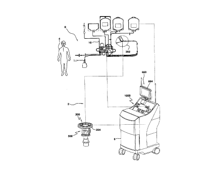
A blood apheresis system 2 is illustrated in Fig. 1
and allows for a continuous blood component separation
process. Generally, whole blood is withdrawn from a
donor/patient 4 and is provided to a blood component
separation device 6 where the blood is separated into the
various component types and at least one of these blood
component types is removed from the device 6. These blood
components may then be provided for subsequent use by
another or may undergo a therapeutic treatment and be
returned to the donor/patient 4.
CA 02218899 1997-ll-12
W O 96/40322 PCT/US96/10212
- 46 -
In the blood apheresis system 2, blood is withdrawn
from the donor/patient 4 and directed through a disposable
set 8 which includes an extracorporeal tubing circuit 10
and a blood processing vessel 352 and which defines a
completely closed and sterile system. The disposable set
8 is mounted on the blood component separation device 6
which includes a pump/valve/sensor assembly 1000 for
interfacing with the extracorporeal tubing circuit 10, and
a channel assembly 200 for interfacing with the disposable
blood processing vessel 352.
The channel assembly 200 includes a channel housing
204 which is rotatably interconnected with a rotatable
centrifuge rotor assembly 568 which provides the
centrifugal forces required to separate blood into its
various blood component types by centrifugation. The blood
processing vessel 352 is interfitted with the channel
housing 204. Blood thus flows from the donor/patient 4,
through the extracorporeal tubing circuit 10, and into the
rotating blood processing vessel 352. The blood within the
blood processing vessel 352 is separated into various blood
component types and at least one of these blood component
types (e.g., platelets, plasma, red blood cells) is
continually removed from the blood processing vessel 352.
Blood components which are not being retained for
collection or for therapeutic treatment (e.g., red blood
cells, white blood cells, plasma) are also removed from the
blood processing vessel 352 and returned to the
donor/patient 4 via the extracorporeal tubing circuit 10.
CA 02218899 1997-11-12
W O 96/40322 PCTAUS96/10212
- 47 -
Operation of the blood component separation device 6
is preferably controlled by one or more processors included
therein, and may advantageously comprise a plurality of
embedded personal computers to accommodate interface with
ever-increasing PC user facilities (e.g., CD ROM, modem,
audio, networking and other capabilities). Relatedly, in
order to assist the operator of the apheresis system 2 with
various aspects of its operation, the blood component
separation device 6 includes a graphical interface 660.
Disposable Set: Extracorporeal Tubin~ Circuit
As illustrated in Figs. 2A-2B, blood-primable
extracorporeal tubing circuit 10 comprises a cassette
assembly 110 and a number of tubing assemblies 20, 50, 60,
80, 90, 100 interconnected therewith. Generally, blood
removal/return tubing assembly 20 provides a single needle
interface between a donor/patient 4 and cassette assembly
110, and blood inlet/blood component tubing subassembly 60
provides the interface between cassette assembly 110 and
blood processing vessel 352. An anticoagulant tubing
assembly 50, platelet collection tubing assembly 80, plasma
collection tubing assembly 90, and vent bag tubing
subassembly 100 are also interconnected with cassette
assembly 110. As will be appreciated, the extracorporeal
tubing circuit 10 and blood processing vessel 352 are
interconnected to combinatively yield a closed disposable
for a single use.
The blood removal/return tubing assembly 20 includes
a needle subassembly 30 interconnected with blood removal
CA 02218899 1997-11-12
WO 96/40322 PCT/US96/10212
-- 48 --
tubing 22, blood return tubing 24 and anticoagulant tubing
26 via a common manifold 28. The needle subassembly 30
includes a needle 32 having a protective needle sleeve 34
and needle cap 36, and interconnect tubing 38 between
needle 32 and manifold 28. Needle subassembly 30 further
includes a D sleeve 40 and tubing clamp 42 positioned about
the interconnect tubing 38. Blood removal tubing 22 may be
provided with a Y-connector 44 interconnected with a blood
sampling subassembly 46.
Cassette assembly 110 includes front and back molded
plastic plates 112 and 114 (see Figs. 4A, 4B and 5) that
ara hot-welded together to define a rectangular cassette
member 115 having integral fluid passageways. The cassette
assembly 110 further includes a number of outwardly
exten~ing tubing loops interconnecting various integral
passageways. The integral passageways are also
interconnected to the various tubing assemblies.
Specifically, cassette assembly 110 includes a first
integral anticoagulant passageway 12Oa interconnected with
the anticoagulant tubing 26 of the blood removal/return
tubing assembly 20. The cassette assembly 110 further
includes a second integral anticoagulant passageway 120b
and a pump-engaging, anticoagulant tubing loop 122 between
the first and second integral anticoagulant passageways
120a, 120b. The second integral anticoagulant passageway
120b is interconnected with anticoagulant tubing assembly
50. The anticoagulant tubing assembly 50 includes a spike
drip chamber 52 connectable to an anticoagulant source,
CA 02218899 1997-11-12
W O 96/40322 PCT~US96/10212
- 49 -
anticoagulant feed tubing 54 and a sterilizing filter 56.
During use, the anticoagulant tubing assembly 50 supplies
anticoagulant to the blood removed from a donor/patient 4
to reduce or prevent any clotting in the extracorporeal
tubing circuit 10.
Cassette assembly 110 also includes a first integral
blood inlet passageway 13Oa interconnected with blood
removal tubing 22 of the blood removal/return tubing
assembly 20. The cassette assembly 110 further includes a
second integral blood inlet passageway 130b and a pump-
engaging, blood inlet tubing loop 132 between the first and
second integral blood inlet passageways 13oa~ 13Ob. The
first integral blood inlet passageway 13Oa includes a first
pressure-sensing module 134 and inlet filter 136, and the
second integral blood inlet passageway 13Ob includes a
second pressure-sensing module 138. The s~con~ integral
blood inlet passageway 130b is interconnected with blood
inlet tubing 62 of the blood inlet/blood component tubing
assembly 60.
Blood inlet tubing 62 is also interconnected with
input port 392 of blood processing vessel 352 to provide
whole blood thereto for processing, as will be described.
To return separated blood components to cassette assembly
110, the blood inlet/blood compon~nt tubing assembly 60
further includes red blood cell(RBC)/plasma outlet tubing
64, platelet outlet tubing 66 and plasma outlet tubing 68
interconnected with corresponding outlet ports 492 and 520,
456, and 420 of blood processing vessel 352. The RBC/
CA 02218899 1997-11-12
W O 96/40322 PCT~US96/10212
- 50 -
plasma outlet tubing 64 includes a Y-connector 70 to
interconnect tubing spurs 64a and 64b. The blood inlet
tubing 62, RBC/plasma outlet tubing 64, plasma outlet
tubing 68 and platelet outlet tubing 66 all pass through
first and second strain relief members 72 and 74 and a
braided bearing member 76 therebetween. This
advantageously allows for a seal-less interconnection, as
taught in U.S. Patent No. 4,425,112. As shown, multi-lumen
connectors 78 can be employed in the various tubing lines.
Platelet outlet tubing 66 of the blood input/blood
component tubing assembly 60 includes a cuvette 65 for use
in the detection of red blood cells (via an interfacing RBC
spillover detector provided on blood component separation
device 6) and interconnects with a first integral platelet
passageway 14Oa of cassette assembly 110. As will be
appreciated, a transparent member could alternatively be
integrated into cassette assembly 110 in fluid
communication with first integral platelet passageway 14Oa
to interface with an RBC spillover detector.
The cassette assembly 110 further includes a pump-
engaging, platelet tubing loop 142 interconnecting the
first integral platelet passageway 14Oa and a second
integral platelet passageway 14Ob. The second integral
platelet passageway 140b includes first and second spurs
144a and 144b, respectively. The first spur 144a is
interconnected with platelet collection tubing assembly 80.
The platelet collection tubing assembly 80 can receive
separated platelets during operation and includes platelet
CA 02218899 1997-11-12
W O 96/40322 PCTAUS96/10212
- 51 -
collector tubing 82 and platelet collection bags 84
interconnected thereto via a Y-connector 86. Slide clamps
88 are provided on platelet collector tubing 82.
The second spur 144b of the second integral platelet
passageway 140b is interconnected with platelet return
tubing loop 146 of the cassette assembly 110 to return
separated platelets to a donor/patient 4 (e.g., upon
detection of RBC spillover during platelet collection).
For such purpose, platelet return tubing loop 146 is
interconnected to the top of a blood return reservoir 150
integrally formed by the molded front and back plates 112,
114 of cassette member 115. As will be further described,
one or more types of uncollected blood components,
collectively referred to as return blood, will cyclically
accumulate in and be removed from reservoir 150 during use.
Back plate 114 of the cassette member 115 also includes an
integral frame corner 116 defining a window 118 through a
corner of cassette member 115. The frame corner 116
includes keyhole recesses 119 for receiving and orienting
the platelet collector tubing 82 and platelet return tubing
loop 146 in a predetermined spaced relationship within
window 118.
The plasma outlet tubing 68 of blood inlet/blood
component tubing assembly 60 interconnects with a first
integral plasma passageway 160a of cassette assembly 110.
Cassette assembly 110 further includes a pump-engaging,
plasma tubing loop 162 interconnecting the first integral
plasma passageway 160a and a second integral plasma
CA 02218899 1997-11-12
W O 96/40322 PCT~US96/10212
- 52 -
passageway 160b. The second integral plasma passageway
160b includes first and second spurs 164a and 164b. The
first spur 164a is interconnected to the plasma collection
tubing assembly 90.
The plasma collection tubing assembly 90 may be
employed to collect plasma during use and includes plasma
collector tubing 92 and plasma collection bag 94. A slide
clamp 96 is provided on plasma collector tubing 92.
The second spur 164b of the second integral plasma
passageway 160b is interconnected to a plasma return tubing
loop 166 to return plasma to donor/patient 4. For such
purpose, the plasma return tubing loop 166 is
interconnected to the top of the blood return reservoir 150
of the cassette assembly 110. Again, keyhole recesses 119
in the frame 116 of cassette assembly 110 are utilized to
maintain the plasma collector tubing 92 and plasma return
tubing loop 166 in a predetermined spaced relationship
within window 118.
The RBC/plasma outlet tubing 64 of the blood
inlet/blood component tubing assembly 60 is interconnected
with integral RBC/plasma passageway 170 of cassette
assembly 110. The integral RBC/plasma passageway 170
includes first and second spurs 17Oa and 17Ob,
respectively. The first spur 17Oa is interconnected with
RBC/plasma return tubing loop 172 to return separated
RBC/plasma to a donor/patient 4. For such purpose, the
RBC/plasma return tubing loop 172 is interconnected to the
top of blood return reservoir 150 of the cassette assembly
CA 02218899 1997-11-12
W O 96/40322 PCT~US96/10212
- 53 -
110. The second spur 170b may be closed off as shown, or
may be connected with an RBC/plasma collection tubing
assembly (not shown) for collecting RBC/plasma during use.
The RBC/plasma return tubing loop 172 (and RBC/plasma
S collector tubing if provided) is maintained in a desired
orientation within window 118 by keyhole recesses 119 of
the frame 116.
Vent bag tubing assembly 100 is also interconnected to
the top of blood return reservoir 150 of cassette assembly
110. The vent bag tubing assembly 100 includes vent tubing
102 and a vent bag 104. During use, sterile air present
since packaging within cassette assembly 110, and
particularly within blood return reservoir 150, cyclically
passes into and back out of vent tubing 102 and vent bag
104, as will be further described.
Vent bag 94 may be provided with a sterile, gas
pressure-relief valve at a top end (not shown). Further,
it should be noted that, as opposed to vent bag tubing
assembly 100, additional integral passageways, integrated
chambers and tubing loops could be included in cassette
assembly 110 to perform the same functions as the vent bag
tubing assembly 100.
The platelet return tubing loop 146, plasma return
tubing loop 166 and RBC/plasma return tubing loop 172 are
interconnected in a row to the top of blood return
reservoir 150 immediately adjacent to forwardly projecting
sidewalls 152 thereof so that the blood components returned
thereby will flow down the inner walls of the blood return
CA 02218899 1997-11-12
W 096/40322 PCTAJS96/10212
- 54 -
reservoir 150. The blood return reservoir 150 includes an
enlarged, forwardly projecting mid-section 154, a reduced
top section 156 and reduced bottom section 158 ( see also
Fig. 5). A filter 180 is disposed in a bottom cylindrical
outlet 182 of the blood return reservoir 150.
A first integral blood return passageway l90a is
interconnected to the outlet 182 of blood return reservoir
150, and is further interconnected to a second integral
blood return passageway l9Ob via a pump-engaging, blood
return tubing loop 192. The second integral blood return
passageway l90b is interconnected with the blood return
tubing 24 of the blood removal/return tubing assembly 20 to
return blood to the donor/patient 4 via needle assembly 30.
AS illustrated in Figs. 2A-2B, pump-engaging tubing
loops 122, 132, 142, 162 and 192 extend from cassette
member 115 to yield an asymmetric arrangement thereby
facilitating proper mounting of cassette assembly 110 on
blood component separation device 6 for use. Relatedly, to
further facilitate loading of cassette assembly 110, it is
noted that the back plate 114 of cassette member 115 iS
preferably molded to present a shallow pan-shaped back
having a rim ext~nA;ng around the entire periphery and
around window 118, the edge of the rim being substantially
coplanar with the back surface of the top, mid and bottom
sections 154, 156, 158 of reservoir 150 and further
defining a recessed region within which first and second
pressure-sensing modules 134 and 138 project.
CA 02218899 1997-11-12
W O 96/40322 PCTAJS96/10212
- 55 -
Tubing assemblies 20, 50, 60, 80, 90 and 100 and
; cassette assembly 110 preferably comprise PVC tubing and
plastic components that permit visual observation and
monitoring of blood/blood components therewithin during
use. Further, it should be noted that thin-walled Pvc
tubing (e.g., less than about 0.023 inch) may be
advantageously employed for approved, sterile docking
(i.e., the direct connection of two pieces of tubing~ for
platelet collector tubing 82 and plasma collector tubing 92
lo and RBC/plasma collector tubing, if provided. Thicker-
walled PVC tubing (e.g., about 0.037 inch or more) is
preferably utilized for pump-engaging tubing loops 132,
142, 162 and 192.
Pump/Valve/Sensor Assembly
As noted, cassette assembly 110 is mounted upon and
operatively interfaces with the pump/valve/sensor assembly
1000 of blood component separation device 6 during use.
The pump/valve/sensor assembly 1000 is angled upward at
about 45~ (see Fig. 1) and as illustrated in Fig. 3
includes a cassette mounting plate 1010, and a number of
peristaltic pump assemblies, flow divert valve assemblies,
pressure sensors and ultrasonic level sensors
interconnected to face plate 6a of blood collection device
6 for pumping, controlling and monitoring the flow of
blood/blood components through extracorporeal tubing
circuit 10 during use.
More particularly, anticoagulant pump assembly 1020 is
provided to receive anticoagulant tubing loop 122, blood
CA 02218899 1997-11-12
W O 96/40322 PCTAJS96/10212
- 56 -
inlet pump assembly 1030 is provided to receive blood inlet
tubing loop 132, platelet pump assembly 1040 is provided to
receive platelet tubing loop 142, plasma pump assembly 1060
is provided to receive plasma tubing loop 162, and blood
return pump assembly 1090 is provided to receive blood
return tubing loop 192. Each of the peristaltic pump
assemblies 1020, 1030, 1040, 1060, and 1090 includes a
rotor 1022, 1032, 1042, 1062 and 1092, and raceway 1024,
1034, 1044, 1064, and 1094 between which the corresponding
tubing loop is positioned to control the passage and flow
rate of the corresponding fluid.
Platelet divert valve assembly 1100 is provided to
receive platelet collector tubing 82 and platelet return
tubing loop 146, plasma divert valve assembly 1110 is
provided to receive plasma collector tubing 92 and plasma
return tubing loop 166, and RBC/plasma divert valve
assembly 1120 is provided to receive RBC/plasma return
tubing loop 172 and RBC/plasma collector tubing if
provided. As noted above, each pair of tubing for
collection or return of separated blood components is
disposed in a predetermined spaced relationship within
window 118 of cassette assembly 110, thereby facilitating
loading relative to the corresponding divert value
assemblies. As will be further described, platelet divert
valve assembly 1100, plasma divert valve assembly 1110 and
RBC/plasma divert valve assembly 1120 each include a rotary
occluding member 1400a, 1400b and 1400c that is selectively
positionable between stationary occluding walls 1104 and
CA 02218899 1997-11-12
W O 96/40322 PCT~US96/10212
- 57 -
1106, 1114 and 1116, and 1124 and 1126, respectively, for
diverting fluid flow through one tubing of the
corresponding pairs of tubings.
Pressure sensors 1200 and 1260 (See also Figs. 4A and
4B) are provided within pump/valve/sensor assembly 1000 to
operatively engage the first and second pressure-sensing
modules 134 and 138 of cassette assembly 110 through
openings 1120 and 1140 of cassette mounting plate 1100.
Similarly, ultrasonic level sensors 1300 and 1320 (see also
lo Fig. 5) are provided to operatively engage the blood return
reservoir 150 cassette assembly 110 through openings 1160
and 1180 of cassette mounting plate 1100.
As shown in Figs. 4A and 4B, the first and second
pressure-sensing modules 134, 138 of cassette assembly 110
each comprise a circular diaphragm 134a, 138a positioned on
a raised cylindrical seat 134b, 138b formed into the back
plate 114 of cassette assembly 110 with a ring-ch~r~
plastic diaphragm retainer 134c, 138c hot-welded to the
raised cylindrical seats 134b, 138b to establish a seal
therebetween. This arrangement allows the diaphragms 134a,
138b to be directly responsive to the fluid pressures
within the first and second integral blood inlet
passageways 13Oa, 13Ob, respectively, and pressure sensors
1200, 1260 to directly access the diaphragms 134a, 138a
through the ring-shaped ret~;n~rs 134c, 138c. By
monitoring the diaphragms 134a, 138a, the pressure sensors
1200, 1260 can monitor the fluid pressure within the first
and second integral blood inlet passageways 13Oa, 13Ob. In
CA 02218899 1997-11-12
W O 96/40322 PCTAJS96/10212
- 58 -
this regard, it should also be noted that since first
integral blood inlet passageway 130a is in direct fluid
communication with blood removal tubing 22, and since blood
removal tubing 22 and blood return tubing 24 are fluidly
interconnected via the common manifold 28, the first
pressure-sensing module 134 will be responsive to and first
pressure sensor 1200 will actually sense the substantially
common pressure in both the blood removal tubing 22 and
blood return tubing 24 during operation.
With further regard to the first pressure-sensing
module 134 and first pressure sensor 1200, Fig. 4A
illustrates an air coupling arrangement that allows for the
sensing of positive and negative pressure changes (i.e.,
causing outward and inward flexure of diaphragm 134a). To
achieve an air seal between the first pressure sensor 1200
and first pressure-sensing module 134, the sensor 1202
includes a resilient (e.g., rubber), cone-shaped engaging
member 1202. The engaging member 1202 is attached to an
air channel member 1204 having a nipple-end 1206 that is
received by beveled cylindrical extension 134d of retainer
134c. Air channel member 1204 further includes an outer,
annular projecting ~h~nnel portion 1208 that contains an O-
ring 1210 for sealed sliding engagement of the air ch~nnel
member 1204 within housing 1212. As illustrated, housing
1212 includes ears 1214 which interface with a floating
positioning member 1216 secured to the face plate 6a of
blood component separation device 6. As shown, a slight
clearance is provided in such interface so as to permit
CA 02218899 1997-11-12
WO 96/40322 PCTrUS96/10212
- 59 -
slight lateral movement of the engaging member 1202 and air
channel member 1204 during loading of the cassette assembly
110. A threaded end 1218 of housing 1212 extends through
the face plate 6a of blood component separation device 6
and receives nut 1220 thereupon, while leaving a slight
clearance between the nut 1220 and face plate 6a. A spring
1222 is positioned within the housing 1212 and acts upon
the annular channel portion 1208 of the air channel member
1204 to provide a spring-loaded interface between the first
pressure sensor 1200 and first pressure-sensing module 134.
Pressure-sensing transducer 1224 engages air channel member
1204 to sense positive and negative pressure changes within
sensing module 134 and provide an output signal in response
thereto during use. As will be further described, the
output signal of pressure transducer 1224 can be employed
to control the operation of blood inlet pump 1030 and blood
return pump 1090 during operation.
With regard to the second pressure-sensing module 138
and the second pressure sensor 1260, Fig. 4B illustrates a
direct contact coupling approach that allows for sensing of
positive pressure changes (i.e., causing outward flexure of
diaphragm 138a). Such contact coupling facilitates loading
since the precise position of the diaphragm 138a relative
to the second pressure sensor 1260 is not critical. As
shown, second pressure sensor 1260 includes a projecting
end portion 1262 that is received by the ring retainer 138c
of sensing module 138 to directly contact diaphragm 138a.
Pressure transducer 1264 is mounted relative to the face
CA 02218899 1997-11-12
W O 96/40322 PCTAJS96/10212
- 60 -
plate 6a of the blood component separation device 6 via a
ring 1266 that threadingly engages a portion of pressure
transducer 1264 ext~n~;ng through the face plate 6a.
Pressure transducer 1264 provides an output signal
responsive to positive pressure changes acting upon
diaphragm 138a.
As shown in Fig. 5, when cassette assembly 110 is
mounted on pump/valve/sensor assembly 1000, the ultrasonic
level sensors 1300 and 1320 will be positioned to monitor
the fluid level in the blood return reservoir 150. More
particularly, upper ultrasonic level sensor 1300 will be
positioned in contact with the reduced top section 156 of
blood return reservoir 150 and lower ultrasonic level
sensor 1320 will be positioned in contact with the reduced
bottom section 158 of blood return reservoir 150.
Ultrasonic sensors 1300, 1320 each comprise pulse/echo
transducers 1302, 1322 having a contact surface (e.g.,
urethane) 1304, 1324 that facilitates divert dry coupling
(i.e., without a gel or other like coupling medium) with
the blood return reservoir 150. By way of example,
ultrasonic sensors may comprise model Z-11405 transducers
offered by Zevex Inc. of 5175 Greenpine Drive, Salt Lake
City, Utah. Pulse/echo transducers 1302, 1322 are disposed
within housings 1306, 1326 for interconnection with face
plate 6a of the blood component separation device 6.
Housings 1306, 1326 include a flange 1308, 1328 for
engaging the front of face plate 6a, and further include a
threaded end 1308, 1328 that extends through the face plate
CA 02218899 1997-11-12
W096/40322 PCT~S96/10212
- 61 -
6a to receive corresponding retaini~g nuts 1310, 1330. A
slight clearance i5 provided for between flange6 1308, 1328
and face plate 6a. Springs 1312, 1332 are positioned
within hou6ing6 1306, 1326 to act upon the corr~sponding
pulse/echo transducers 1302, 1332 via E-clips 1314, 1334
disposed therebetween. Such spring loading of pulse/echo
transducers 1302, 1332 yields a predetermined desired
loading pres6ure for pulce/echo transducers 1302, 1332
relative to rPservoir 150 during operation (e.g., at least
aboùtl~ lbs~). O-rings 1316, 1336 are provided
intermediate pulse~echo transducers 1302, 1322 and housings
13~6, 1326 to provide a sliding saal therebetween. Cablçs
1318, 1338 ~re interconnected to transducers 1302, 1322 to
provide pulsing signals and return detected echo signals.
By gausing the presence and timing o~ return
ultrasonic echo pulses each of sen~ors 1300 and 1320 can be
employed to monitor the presence or absence of fluid within
their correspo~in~ echo region6 within the blood return
reservoir 150, and perm~t blood component separation
20 device 6 to provide pump ~o-~ol signals in r~sponce
thereto. More particularly, when return blood accumulate~
up into the echo region of upper level ~ensor 1300 during
blood proces6ing, ultrasonic pul~es emitte~ by upper level
sensor 1300 will readily pa~ through the return ~lood and
~ 25 reflect off of the oppo6ing re~ervoir out~ide s$dewall/air
interface to yield echo pul6e6 having a predetermined
minimum ~LL~r.~th that are detected by upper sen60r 1300
within a predeteL ~ ned time pQriod after trans~il-E;ion.
APulENDED SHE~
.
CA 02218899 1997-ll-12
W O 96/40322 PCT~US96/10212
- 62 -
When such echo pulses are received, upper sensor 1300
provides a signal that is used by blood component
separation device 6 to initiate operation of blood return
pump 1090 so as to remove accumulated return blood from the
blood return reservoir 150 and transfer the same to the
donor/patient 4.
When blood return pump 1090 has removed return blood
from the reservoir 150 down into the lower echo region,
ultrasonic pulses emitted by lower level sensor 1320 will
not be reflected at the opposing reservoir outside
sidewall/air interface to yield echo pulses having a
predetermined minimum strength for detection by lower level
sensor 1320 within a predetermined time period after
transmission. When this occurs, lower level sensor 1320
will fail to provide corresponding signals to blood
component separation device 6, and blood component
separation device 6 will automatically stop blood return
pump 1090 to stop further removal of return blood from the
blood return reservoir 150, and return blood will again
begin accumulating in reservoir 150. Thus, in the blood
processing mode, blood component separation device 6 will
not initiate operation of blood return pump 1090 unless and
until it receives signals from upper ultrasonic sensor 1300
(the provisions of such signals indicating the presence of
return blood in the upper echo region), and will thereafter
automatically stop operation of blood return pump 1090 if
it fails to receive signals from ultrasonic sensor 1320
CA 02218899 1997-11-12
W O 96/40322 PCTAJS96/10212
- 63 -
(the failure to receive such signals indicating the absence
of return blood in the lower echo region).
In an initial blood prime mode, whole blood is
introduced to reservoir 150 from a donor/patient 4 through
blood return tubing 24, integral passageways l90a, l90b,
and tubing loop 192 via reverse operation of blood return
pump 1090. When such whole blood accumulates up into the
echo region of lower level sensor 1320, ultrasonic pulses
emitted by lower level sensor 1320 will pass through the
blood and reflect off of the opposing reservoir outside
sidewall/air interface to yield echo pulses having a
pradetermined minimum strength that are detected by lower
level sensor 1320 within a predetermined time period after
transmission. When such echo pulses are received in the
blood prime mode, lower level sensor 1320 provides a signal
that is used by blood component separation device 6 to turn
off blood return pump 1090 and end the blood prime mode.
Blood component separation device 6 then initiates the
blood processing mode.
It is contemplated that ultrasonic sensors 1300, 1320
can be utilized for indicating and/or confirming the
desired mounting relationship of cassette member 15 on
cassette mounting plate 1010 for blood processing
operations. For such purposes, if the desired mounting has
been achieved, the sensors 1300, 1320 should be coupled to
reservoir 150 so that ultrasonic pulses reflect off the
interface between the inside surface of the back sidewall
of reservoir lS0 (i.e., the sidewall contacted by the
CA 02218899 1997-11-12
W O 96/40322 PCTAUS96/10212
- 64 -
sensors 1300, 1320) and contained air within reservoir 150,
and be received with a predetermined minimum strength
within a predetermined time period after tr~n! i~sion. If
such echo pulses are received with respect to both
ultrasonic sensors 1300, 1320, the desired loading
relationship will be indicated and/or confirmed. Further,
it is noted that ultrasonic sensors 1300, 1320 may be
employable to sense echo pulses from the interfaces between
fluid contained within the reservoir 150 and the inside
surface of the outer sidewall of reservoir 150 in the upper
and lower echo regions of the reservoir during operation.
If such echo pulses are detectible within corresponding,
predetermined time windows, corresponding signals provided
by ultrasonic sensors 1300, 1320 can provide a further
input for blood component separation device 6 to control
operation of blood return pump 1090.
It should be noted that in the illustrated
arrangement, the upper and lower ultrasonic sensors 1300
and 1320 advantageously operate via coupling with reduced
cross-sectional portions 156 and 158 of reservoir 150. The
reduced upper and lower reservoir portions 154,
158,accommodate reliable detection of echo pulses when
fluid is present in the upper and lower echo regions, and
the enlarged mid-portion 158 provides satisfactory return
blood holding capabilities.
Fig. 6 shows the components of each of the platelet
divert valve subassembly 1100, plasma divert valve
subassembly 1100 and RBC/plasma divert valve subassembly
CA 02218899 1997-11-12
W O 96/40322 PCT~US96/10212
- 65 -
1120. Each subassembly includes a rotary occluder member
1400 having a headed shaft member 1402 and barrel sleeve
1404 positioned thereupon and rotatable relative thereto.
The subassembly further comprises a main valve shaft 1406
positioned within a valve body 1408 that is secured to face
plate 6a of blood component separation device 6. An 0-
ring 1410 is provided in a recess on the main valve shaft
1406 to provide a sliding seal between main valve shaft
1406 and extensions 1412 of main valve body 1408. The main
valve shaft 1406 is driven by a motor 1414 mounted on mount
plate 1416 that in turn is mounted to and set off from face
plate 6a by standoff legs 1418.
For positioning rotary occluder member 1400 for
occlusion relative to one of the co-acting walls (e.g. 1104
or 1106 of the plasma divert valve subassembly 1100) or for
loading/removal of the cassette assembly 110 on the blood
component separation device 6, each divert valve
subassembly comprises three optical through-beam sensors
1420 (two shown) interconnected to standoff legs 1418 via
support layer 1419, and an optical interrupter member 1422
interconnected to the main valve shaft 1406. Each through-
beam sensor 1420 is of a U-shape configuration with a
radiation source and radiation receiver disposed on
opposing legs. The optical interrupter member 1422 has an
inverted cup configuration with its sidewalls interposed
and rotatable between the opposing legs of sensors 1420.
The optical interrupter member 1422 includes a single
window 1424 therethrough. As will be appreciated, the
CA 02218899 1997-11-12
W O 96/40322 PCT~US96/10212
- 66 -
position of the rotary occluder member 1400 relative to the
window 1424 of the optical interrupter 1422 is known, such
that when the optical window 1424 passes between the
opposing radiation source/receiver for a given optical
sensor 1420, the optical sensor 1420 will provide a signal
in response to the through-beam (indicating the position of
the rotary occluder member 1400), and the signal is
employed to control the operation of motor 1414 to dispose
rotary occluder member 1400 in the desired position. To
provide/route such signals, the support layer 1419 may
advantageously comprise a printed circuit board. Optical
sensors 1420 are preferably positioned slightly "upstream"
of predetermined stop regions for occlusion or cassette
loading so that motor 1414 will be able to dynamically slow
down and position rotary occluder member 1400 within such
regions as desired. To insure the desired positioning for
occlusion, however, stops 1426 are provided on main valve
shaft 1406 to co-act with cross-pin 1428 interconnected to
main valve shaft 1406 to insure stop positioning of rotary
occluder member 1400 relative to the desired occluding
wall.
Each of the occluding walls 1104 and 1106, 1114 and
1116, and 1124 and 1126, are provided with arcuate recesses
(not shown) for receiving the rotatable barrel sleeve on
1404 of rotary occluder members 1400a, 1400b and 1400c. By
way of example, such arcuate recesses may have an arc
length of 20~ and provide a tolerance range for positioning
the rotary occluder members 1400a, 1400b, 1400c to achieve
CA 02218899 1997-11-12
W O 96/40322 PCT~US96/10212
- 67 -
the desired tubing occlusion. As illustrated in Fig. 3,
~ occluding wall 1106 may be provided with a resilient pad to
best accommodate the use of approved, sterile-docking
tubing for platelet collector tubing 82. Further, and as
noted above, sterile-docking tubing may be advantageously
employed for plasma collector tubing 92 and, if provided,
RBC/plasma collector tubing (not shown), and corresponding
resilient pads (not shown) may be provided on occluding
walls 1114 and 1124. In this regard, given the thinness
and relatively high-spring rate of sterile-docking tubing,
the use of resilient pads in connection therewith increases
the wearability of the sterile docking tubing.
In order to establish an initial predetermined set
position of the cassette assembly 110 relative to the
pump/valve/sensor assembly 1000, the cassette assembly 110
includes downwardly ext~n~;ng corner positioning tabs 15
and top and bottom edge lips 17 that engage corresponding
lower channel projections 1102a on cassette mounting plate
1010 and upper channel projections 1102b on a pivotable
spring-loaded interlock member 1104 that extends across the
top edge of cassette mounting plate 1010. The interlock
member 1104 is spring-loaded to positively engage cassette
assembly 110 upon loading via a spring positioned within
- housing 1106, and is provided with a tab 1108 for pivotable
movement during cassette lo~ing against the spring loading
pressure. Preferably, interlock member 1104 is disposed
relative to the raceway 1094 of return pump assembly 1090,
such that when cassette assembly 110 is fully loaded for
CA 02218899 1997-11-12
W 096/40322 PCT~US96/10212
- 68 -
operation on blood component separation device 6, raceway
1094 will physically restrict interlock member 1104 from
being pivoted, thereby advantageously restricting removal
and/or movement of cassette assembly 110 during use.
After cassette assembly 110 has been secured on the
cassette mounting plate 1010, a loading assembly 1500
retracts the cassette mounting plate 1010 towards face
plate 6a of the blood component separation device 6 to
establish the above-noted, fully-loaded pump, valve and
sensor relationships. As illustrated in Fig. 7, loading
assembly 1500 includes two posts 1502 upon which cassette
mounting plate 1010 is supportably interconnected. The
posts 1502 extend through the face plate 6a of blood
collection device 6a and are interconnected to a cross-
connect member 1504. A drive nut 1506 iS secured to cross-
connect member 1504 and engages a drive screw 1508. The
drive screw 1508 iS in turn rotatably interconnected to a
drive motor 1510 via coupling 1512, the drive motor 1510
being mounted on a platform 1514 which is supportively
interconnected to face plate 6a via standoff legs 1516.
The drive motor 1510 operates to turn drive screw 1508 SO
as to cause cross-connect member 1504 and posts 1502 to
selectively move cassette mounting plate 1010
perpendicularly towards face plate 6a during loading
procedures and perpendicularly away from face plate 6a for
unloading of the cassette assembly 110.
To establish the desired position of cassette mounting
plate 1010, U-shaped optical through-beam sensors 1520a and
CA 02218899 1997-11-12
W O 96/40322 PCT~US96/10212
- 69 -
1520b are mounted on post bearing holders 1522 and an
optical occluder member 1524 having a window 1526 is
interconnected to the cross-connect member 1504. Each oE
the U-shaped optical sensors 1520a 1520b includes a
radiation source and radiation receiver positioned on
opposing extPn~ing legs and the optical occluder member
1524 extends between such legs. Since the relative
positions between cassette mounting plate 1010 and optica:L
sensors 1520a, 1520b are known, by detecting the passage oiE
radiation through window 1526 using optical sensors 1520
and providing a signal responsive thereto the position o~E
cassette mounting plate 1010 for loading and unloading can
be automatically established. For example, when a through--
beam is received by optical sensor 152Ob, a signal will be
provided to stop motor 1510 in a position wherein cassette
assembly 110 will be fully loaded on the pump/valve/sensor
assembly 1000 for operation.
To confirm such loaded condition, first and seconcl
pressure sensors 1200 and 1260 and upper and lower
ultrasonic sensors 1300 and 1320 may be employed. For
example predetermined minimum pressure values can be
established and actual pressures measured for each of the
first and second pressure sensors 1200 and 1260 to confi~
the desired loading of cassette assembly 110. Further ancl
of particular interest ultrasonic sensors 1300 and 1320
can be advantageously employed to confirm the desirecl
loading since upon proper coupling to reservoir 150 echo
pulses should be reflected off of the internal sidewall/air
CA 02218899 1997-11-12
W O 96/40322 PCTAUS96/10212
- 70 -
interface with a predetermined minimum strength within a
predetermined time period as noted above.
It should be noted that drive motor 1510 preferably
includes a number of reduction gears with the last gear
being operatively associated with a slip clutch plate to
limit the maximum amount of force that may be applied by
cassette mounting plate 1010 (e.g., to an object between
cassette mounting plate 1010 and face plate 6a).
Relatedly, it is preferable to include control capabilities
lo wherein during a load cycle if the window 1526 of optical
occluder 1524 has not moved from its position within the
first optical pass through sensor 1520a to a position
within the second optical pass through sensor 152Ob within
a predetermined time period, drive motor 1510 will
automatically either stop or reverse operations.
To ~l -~ize the loading process, loading assembly
1500 initially disposes cassette mounting plate 1010 in an
extended position. With the cassette mounting plate 1010
in such extended position, interlock member 1104 is pivoted
away from cassette mounting plate 1010 and cassette
assembly 110 is positioned on cassette mounting plate 1010
with bottom edge lips 17 of cassette assembly 110 being
received by lower channel projections 1102a of cassette
mounting plate 1010 and, upon return pivotal movement of
interlock member 1104, top edge lips 17 of cassette
assembly 110 being engaged by upper channel projections
1102b on interlock member 1104. Loading assembly 1500 is
then operated to retract cassette mounting plate 1010 from
CA 02218899 1997-11-12
W O 96/40322 PCTAJS96/10212
- 71 -
its extended position to a retracted position, wherein
~ tubing loops 122, 132, 162, 142, 192 of cassette assembly
110 are automatically positioned within the corresponding
peristaltic pump assemblies 1020, 1030, 1060, 1040 and
1090. For such purposes, the rotors of each of the
peristaltic pump assemblies are also operated to achieve
loaded positioning of the corresponding tubing loops.
Further, it should be noted that for loading purposes, the
rotary occluder members 1400a, 1400b and 1400c of the
divert valve assemblies 1100, 1110 and 1120 are each
positioned in an intermediate position so as to permit th.e
corresponding sets of tubing to be positioned on each sid.e
thereof.
Upon retraction of the cassette mounting plate 1010,
spring-loaded, ultrasonic sensors 1300 and 1320 wil.l
automatically be coupled to reservoir 150 and first and
second pressure sensors 1200 and 1260 will automaticall.y
couple to first and second pressure-sensing modules 134 ar.ld
138 of cassette assembly 110. In this fully-loadecl,
retracted position, the cassette assembly 110 will be
restricted from movement or removal by the above-note!d
physical restriction to pivotal movement of interloc:k
member 1104 provided by raceway 1094 of return pump
assembly 1090.
It is also noted that during loading of casset1:e
assembly 110 on the blood component separation device 6,
cuvette 65 is positioned within an RBC spillover detector
1600 (e.g., an optical sensor for detecting the presence of
CA 02218899 1997-11-12
W O 96/40322 PCTAUS96/10212
- 72 -
any red blood cells in the separated platelet fluid stream
and providing a signal response thereto) provided on the
face plate 6a. Similarly, a portion of anticoagulant tubing
54 is positioned within an AC sensor 1700 (e.g., an
ultrasonic sensor for confirming the presence of
anticoagulant and providing a signal in the absence
thereof) also provided in face plate 6a.
To unload cassette assembly 110 after use, the
occluding members 1400a, 1400b and 1400c of each divert
value assembly are again positioned in an intermediate
position between the corresponding occluding walls and
loading assembly 1500 is operated to move cassette mounting
plate 1010 from its retracted position to its extended
position. Contemporaneously, the rotors of the various
peristaltic pump assemblies are operated to permit the
corresponding tubing loops to exit the same. In the
extended position, the interlock member 1104 is pivoted out
of engagement with cassette assembly 110 and cassette
assembly 110 is removed and disposed of.
operation of Extracorporeal Tubing Circuit
and Pump/Valve/Sensor Assembly
In an initial blood prime mode of operation, blood
return pump 1090 is operated in reverse to transfer whole
blood through blood removal/return tubing assembly 20,
integral blood return passageway 190, blood return tubing
loop 192 and into reservoir 150. Contemporaneously and/or
prior to the reverse operation of blood return pump 1090,
anticoagulant peristaltic pump 1020 is operated to prime
CA 02218899 1997-11-12
W O 96/40322 PCTAJS96/10212
- 73 -
and otherwise provide anticoagulant from anticoagulant
tubing assembly 50, through anticoagulant integral
passageway 120, and into blood removal tubing 22 and blood
return tubing 24 via manifold 28. When lower level
ultrasonic sensor 1320 senses the presence of the whole
blood in reservoir 150 a signal is provided and blood
component separation device 6 stops blood return
peristaltic pump 1090. As will be further discussed,
during the blood prime mode blood inlet pump 1030 is also
operated to transfer blood into blood inlet integral
passageway 130, through blood inlet tubing loop 132 and
into blood inlet/blood 5 , onent tubing assembly 60 tc~
prime the blood processing vessel 352.
During the blood prime mode, vent bag assembly 100
receives air from reservoir 150. Relatedly, the occluding
members 1400a, 1400b, 1400c of divert assemblies 1100,
1110, 1120 are each preferably positioned to divert flow to
the reservoir 150. It should also be noted that to
facilitate blood priming, the cassette assembly 110 is
angled upward at about 45~ in its loaded position, and th,e
integral passageways of cassette member 115 are disposed SlD
that all blood and blood component inlet paths provide fo:r
a bottom-to-top plug flow.
- In the blood processing mode, the blood inlet
peristaltic pump 1030, platelet peristaltic pump 1040 an,d
plasma peristaltic pump 1060 are operated continuously, anl~
the occluding members 1400a, 1400b, 1400c are positione,d
for collection or return of corresponding blood components,
CA 02218899 1997-11-12
W O 96/40322 PCTAJS96/10212
- 74 -
as desired.. During a blood removal submode, blood return
peristaltic pump 1090 is not operated so that whole blood
will pass into blood removal/return tubing assembly 20 and
transferred to processing vessel 352 via the cassette
assembly 110 and blood inlet/blood component tubing
assembly 60. In the blood removal submode, uncollected
blood components are transferred from the processing vessel
352 to cassette assembly 110, and uncollected components
are passed into and accumulate in reservoir 150 up to a
predetermined level at which upper level ultrasonic sensor
1300 provides signals used by blood component separation
device 6 to end the blood removal submode and initiate a
blood return submode. More particularly, blood return
submode is initiated by forward operation of blood return
peristaltic pump 1090. In this regard, it should be
appreciated that in the blood return submode the volume
transfer rate of return blood through blood return tubing
loop 192 utilizing blood return peristaltic pump 1090 is
established by blood component separation device 6,
according to a predetermined protocol, to be greater than
the volume transfer rate through blood inlet tubing loop
132 utilizing blood inlet peristaltic pump 1030. As such,
the accumulated blood in reservoir 150 is transferred into
the blood return tubing of blood removal/return tubing
assembly 20 and back into the donor/patient 4. During the
blood processing mode, when the accumulated return blood in
reservoir 150 is removed down to a predetermined level,
lower level ultrasonic sensor 1320 will fail to provide
CA 02218899 1997-11-12
W O 96MO322 PCT~US96/10212
- 75 -
signals to blood component separation device 6 whereupon
blood component separation device 6 will automatically stop
blood return peristaltic pump 1090 to end the blood return
submode. This automatically serves to reinitiate the bloo~
..--o~l submode since blood inlet peristaltic pump 1030
continuously operates.
During the blood processing mode pressure sensor 1200
senses negative/positive pressure changes within the blood
removal tubing 22 blood return tubing 26, via firslt
integral blood inlet passageway 130a. Such monitored
pressure changes are C~l -n; cated to blood componen1t
separation device 6 which in turn controls blood inlet puml?
1030 and return pump 1090 so as to maintain fluid pressures
within predetermined ranges during the blood removal and
th2 blood return submodes. Specifically during the blood
re~moval submode if a negative pressure is sensed tha1
exl~eeds (i.e., is less than) a predetermined negative limit:
value, then blood component separation device 6 will slow
down operation of blood inlet pump 1030 until the sensecl
negative pressure is back within an acceptable range.
During the blood return submode, if a positive pressure is
sensed that exceeds (i.e., is greater than) a predeterminecl
po-itive limit value, then blood component separation
device 6 will slow down operation of blood return pump 1090
un1;il the sensed positive pressure is back within an
acceptable range.
Pressure sensor 1260 monitors the positive pressure
wi1:hin the second integral blood inlet passageway 13Ob ancl
CA 02218899 1997-11-12
W O 96/40322 PCT~US96/10212
- 76 -
blood inlet tubing 62. If such sensed positive pressure
exceeds a predetermined maximum value, blood component
separation device 6 Will initiate appropriate responsive
action, including, for example, slowing or stoppage of the
centrifuge and peristaltic pumps.
During the blood processing mode, blood component
separation device 6 controls the operation of anticoagulant
pump 1020 according to a predetermined protocol and
responsive to signals provided by AC sensor 1700 (e.g.,
indicating a depleted anticoagulant source). Also, blood
component separation device 6 also controls the operation
of divert assemblies 1100, 1110, 1120 according to
predetermined instructions and further pursuant to any
detect signals provided by RBC spillover detector 1600. In
the latter regard, if an RBC spillover in the separated
platelet stream is detected, blood component separation
device 6 will automatically cause occluder member 1400a to
divert the separated platelet stream to the return
reservoir 150 until the RBC spillover has cleared, thereby
keeping red blood cells from undesirably passing into
platelet collector tubing assembly 80.
In normal operation, whole blood will pass through
needle assembly 30, blood removal tubing 22, cassette
assembly 110 and blood inlet tubing 62 to processing vessel
352. As will be further described in detail, the whole
blood will then be separated in vessel 352. A platelet
stream will pass out of port 420 of the vessel, through
platelet tubing 66, back through cassette assembly 110, and
CA 02218899 1997-11-12
W O 96/40322 PCTAiS96/10212
- 77 -
will then be either collected in collector assembly 80 o:r
- diverted to reservoir 150. Similarly, separated plasma
will exist vessel 352 through port 456 to plasma tubing 6~3
back through cassette assembly 110, and will then either be
collected in platelet tubing assembly 90 or diverted to
reservoir 150. Further, red blood cells and plasma (and
potentially white blood cells) will pass through ports 49;2
and 520 of vessel 352 through RBC/plasma tubing 64, through
cassette assembly 110 and into reservoir 150. In this
regard, it is contemplated that second spur 170b o:E
integral passageway 170 may be connected to a separate
RBC/plasma collector tubing assembly (not shown) and
RBC/plasma divert valve assembly 1120 could be operated for
the collection of RBC/plasma.
As noted above, when uncollected platelets, plasma,
and RBC/plasma (and potentially white blood cells) have
accumulated in reservoir 150 up to upper ultrasonic leve:L
sensor 1300, operation of return peristaltic pump lO9o wil:L
be initiated to remove the noted components from reservoir
150 and transfer the same back to the donor/patient 4 via
the return tubing 24 and needle assembly 20. When the
fluid level in the reservoir 150 drops down to the level oiE
the lower ultrasonic level sensor 1320, the return
peristaltic pump 1090 will automatically turn of~E
reinitiating the blood removal submode. The cycle between
blood removal and blood return submodes will then continue
until a predetermined amount of platelets or other
collected blood components have been harvested.
CA 02218899 1997-11-12
W 096/40322 PCTAJS96/10212
- 78 -
In one embodiment, reservoir 150 and upper and lower
ultrasonic sensors 1300 and 1320 are provided so that,
during the blood processing mode, approximately 50
milliliters of return blood will be removed from reservoir
150 during each blood return submode and accumulated during
each blood removal submode. Relatedly, in such embodiment,
lower and upper level triggering by ultrasonic sensors 1300
and 1320 occurs at fluid volumes of about 15 milliliters
and 65 milliliters, respectively, within reservoir 150.
For such embodiment, it is also believed desirable to
provide for a volume transfer operating rate range of about
30 to 300 milliliters/minute through blood return tubing
loop 192 utilizing return pump 1090, and a volume transfer
operating rate range of about 20 to 140 milliliters/minute
through blood inlet tubing loop 132 utilizing inlet pump
1030. Additionally, for such embodiment a negative
pressure limit of about -250 mmHg and positive pressure
limit of about 350 mmHg is believed appropriate for
controlling the speed of inlet pump 1030 and return pump
1090, respectively, in response to the pressures sensed in
first pressure-sensing module 134. A positive pressure
limit of about 1350 mmHg within second sensing module 138
is believed appropriate for triggering slow-down or
stoppage of the centrifuge and pumps.
Channel Housing
The channel assembly 200 is illustrated in Figs. 8-23B
and includes a channel housing 204 which is disposed on the
rotatable centrifuge rotor assembly 568 (Figs. 1 and 24)
CA 02218899 1997-11-12
, WO 96~40322 ~CT~S9~/~021
- 79 -
and which receives a dispo~able blood proce5sing vessel
- 352. Re~erring more specifically to Fig6. 8-15, the
channel housing 204 has a generally cylindrically-6haped
perimeter 206 with a diameter of pref'erably no ~ore than
,Z50 r~
aboutl(10 inches~' to achieve ~ desired size for the ~lood
component separation device 6 ~e.g., to enh~nce i1:s
portability). An opening 328 extends longit~ ;n~l:Ly
through the channel housing 204 and contains an axis 3;24
about which the channel housing 204 rotates. l'he channel
housing 204 may ~e formed from materials such as delrin,
polycarbonate, or cast aluminum and may include various
cut-outs or additions to achieve weight reductions and/or
rotational balancQ.
The primary function of the channel housing 204 is to
provide a mounting for the blood proces~ing vessel 352 such
that the blood D~ay be separated into the blood component
types in a desired manner. In this regard, the chann~el
housing 204 includes a generally concave ~hAnnel 208 in
which the blood proce6sing ves~el 3S2 i~ positioned. T'he
channel 208 is principally defined by an inner rh~nn~l wall
212, an outer ch;~nr~t wall 216 which is radially spaced
from the inner channel wall 212, and a chAnr~ ase 220
which is positioned therebetwe~n. The rh~n~l 208 also
extends from a ir~t end 284 generally curvilinearly about
a rotational axis 324 of the rh~nr~l hous.ing 204 to a
second end 288 ~hich overlap6 with the first end 284 such
that a continuous flow path is provided about the
rotational axis 324. That i~, the angular di~.po6ition
A',~.E,'J'DS'~ E-
.
CA 02218899 1997-11-12
W 096/40322 PCTAJS96/10212
- 80 -
between the first end 284 of the channel 208 and the second
end 288 of the channel 208 is greater than 360~ and up to
about 390~, and in the illustrated embodiment is about
380~. Referring to Fig. 15, this angular disposition is
measured by the angle ,t~, along a constant radius arc,
between a first reference ray 336 which extends from the
rotational axis 324 to the first end 284, and a second
reference ray 340 which extends from the rotational axis
324 to the second end 288 of the channel 208.
The blood processing channel vessel 352 iS disposed
within the channel 208. Generally, the channel 208
desirably allows blood to be provided to the blood
processing vessel 352 during rotation of the channel
housing 204, to be separated into its various blood
component types by centrifugation, and to have various
blood component types removed from the blood processing
vessel 352 during rotation of the channel housing 204. For
instance, the channel 208 is configured to allow for the
use of high packing factors (e.g., generally a value
reflective of how "tightly packed" the red blood cells and
other blood component types are during centrifugation and
as will be discussed in more detail below). Moreover, the
channel 208 also desirably interacts with the blood
processing vessel 352 during centrifugation (e.g., by
ret~;ning the blood processing vessel 352 in the channel
208 and by maintaining a desired contour of the blood
processing vessel 352). In addition, the channel 208
allows for a blood priming of the blood processing vessel
CA 02218899 1997-11-12
WO 96/40322 PCTGUS96/10212
- 81 -
352 (i.e., using blood as the first liquid which is
- provided to the blood processing vessel 352 in an apheresis
procedure).
The above-identified attributes of the channel 208 are
provided primarily by its configuration. In this regard,
the channel housing 204 includes a blood inlet slot 224
which is generally concave and which intersects the channel
208 at its inner channel wall 212 in substantially
perpendicular fashion (e.g., the blood inlet slot 224
interfaces with the inner channel wall 212). A blood inlet
port assembly 388 to the interior of the blood processing
vessel 352 is disposed in this blood inlet slot 224 such
that blood from the donor/patient 4 may be provided to the
blood processing vessel 352 when in the channel 208. In
order to retain a substantially continuous surface along
the inner channel wall 212 during an apheresis procedure
and with the blood processing vessel 352 being pressurized,
namely by reducing the potential for the blood inlet port
assembly 388 deflecting radially inwardly within the blood
inlet slot 224, a recess 228 is disposed on the inner
channel wall 212 and contains the end of the blood inlet
slot 224 (e.g., Fig. 14A). This recess 228 receives a
shield 408 which is disposed about the blood inlet port
assembly 388 on the exterior surface of the blood
processing vessel 352 as will be discussed in more detail
below.
As illustrated in Figs. 8-9, an RBC dam 232 of the
channel 208 is disposed in a clockwise direction from the
CA 022l8899 l997-ll-l2
W 096/40322 PCTrUS96/10212
- 82 -
blood inlet slot 224 and whose function is to preclude RBCs
and other large cells such as WBCs from flowing in a
clockwise direction beyond the RBC dam 232. Generally, the
surface of the RBC dam 232 which interfaces with the fluid
containing volume of the blood processing vessel 352 may be
defined as a substantially planar surface or as an edge
adjacent the collect well 236. At least in that portion of
the channel 208 between the blood inlet port 224 and the
RBC dam 232, blood is separated into a plurality of layers
of blood component types including, from the radially
outermost layer to the radially innermost layer, red blood
cells ("RBCs"), white blood cells ("WBCs"), platelets, and
plasma. The majority of the separated RBCs are removed
from the channel 208 through an RBC outlet port assembly
516 which is disposed in an RBC outlet slot 272 associated
with the channel 208, although at least some RBCs may be
removed from the channel 208 through a control port
assembly 488 which is disposed in a control port slot 264
associated with the channel 208.
The RBC outlet port slot 272 iS disposed in a
counterclockwise direction from the blood inlet slot 224,
is generally concave, and intersects the chAnnel 208 at its
inner channel wall 212 in substantially perpendicular
fashion (e.g., the RBC outlet slot 272 interfaces with the
inner channel wall 212). An RBC outlet port assembly 516
to the interior of the blood processing vessel 3 52 is
disposed in this RBC outlet slot 272 such that separated
RBCs from the apheresis procedure may be continually
CA 02218899 1997-11-12
W O 96/40322 PCT~US96/10212
- 83 -
removed from the blood processing vessel 352 when in th~e
channel 208 (e.g., during rotation of the channel housing
204). In order to retain a substantially continuous
surface along the inner channel wall 212 during an
apheresis procedure and with the blood processing vessel
352 being pressurized, namely by reducing the potential for
the RBC outlet port assembly 516 deflecting radially
inwardly within the RBC outlet slot 272, a recess 276 is
disposed on the inner channel wall 212 and contains the enld
of the RBC outlet slot 272 (e.g., Figs. 14A, 14B). This
recess 276 receives a shield S38 which is disposed about
the RBC outlet port assembly 516 on the exterior surface of
the blood processing vessel 352 as will be discussed in
more detail below.
The control port slot 2 64 is disposed in a
counterclockwise direction from the RBC outlet slot 272, is
generally concave, and intersects the channel 208 at its
inner channel wall 212 in substantially perpendicular
fashion (e.g., the control port slot 264 interfaces with
the inner rh~nnel wall 212). A control port assembly 488
to the interior of the blood processing vessel 352 is
disposed in the control port slot 264 (e.g., Figs. 14A and
C). In order to retain a substantially continuous surface
~ along the inner channel wall 212 during an apheresis
~ 25 procedure and with the blood processing vessel 352 being
pressurized, namely by reducing the potential for the
control port assembly 488 deflecting radially inwardly
within the control port slot 264, a recess 268 is disposed
CA 02218899 1997-11-12
~ ~ W096/40322 nCT~59i,'1021'
- 8~ -
on the inner channel wall 212 and contains the end of the
control port slot 264. This recess 268 receives a ~hield
508 which is disposed about the control port ~ssembly 488
on the exterior surface of the blood processing vessel 352
as will be discussed in ~ore detail below.
The portion of thQ rh~n~el 208 extending between th,e
control port 510t 264 and the RBC dam 232 may be
characterized as the rirSt stage 312 of the channel 20~,.
The first stage 312 is configured to remove pr~marily ~BC:s
lo from the channel 208 by utilizing a re~erse flow i.n
relation to the flow of platelet-rich plasma through the
channel 208 which is in a clockwise dire~tion. In th:Ls
regard, the outer chann~l wall 216 extends along a
curviline~r path fro2 the RBC dau 232 to the ~lood inlet
lS slot 224 generally progressing outwardly away from the
rotational axis 324 of the channel housing 204. That is;,
the radial disposition of the outer ch~n~l wall 216 at the
RBC dam 232 i5 less than the radial ~i~po~ition o~ the
outer channel wall 216 at the blood inlet 610t 224. ~e
portion of the RBC outlet slot 272 interfacing with the
channel 208 is al~o disposQd more radially outwardly th;~n
the portion of the ~lood inlet 510t 224 which interfaces
with the c~Annel 208.
In the fir~st 6tage 312, blood i~ ~ga~ separated into
2~ a plurality of layer~s of ~lood component types including,
from the radlally outermo~t layer to the radially innermost
l~yer, red blood cells (~R3Cs~), white ~lood cells
(nWBCsn), platelets, and pla~ma. As auch, the RBC5
Ai~ --t . ~ r~
CA 02218899 1997-11-12
W O 96/40322 PCT~US96/10212
- 85 -
sediment against the outer channel wall 216 in the first;
- stage 312. By configuring the RBC dam 232 such that it is
a section of the channel 210 which extends further inwardl~
toward the rotational axis 324 of the channel housing 204l
this allows the RBC dam 232 to retain separated RBCs ancl
other large cells as noted within the first stage 312
That is, the RBC dam 232 functions to preclude RBCs from
flowing in a clockwise direction beyond the RBC dam 232.
Separated RBCs and other large cells as noted are
lo removed from the first stage 312 utilizing the above-noted
configuration of the outer channel wall 216 which induces
the RBCs and other large cells as noted to flow in a
counterclockwise direction (e.g., generally opposite to the
flow of blood through the first stage 312). Specifically,
separated RBCs and other large cells as noted flow througl
the first stage 312 along the outer rh~n"~l wall 216, paslt
the blood inlet slot 224 and the correspon~;ng blood inlelt
port assembly 388 on the blood processing vessel 352, an~1
to an RBC outlet slot 272. In order to reduce the
potential for counterclockwise flows other than separated
RBCs being provided to the control port assembly 48B
disposed in the control port slot 264 (e.g., such that
there is a sharp demarcation or interface between RBCs and
~ plasma proximate the control port slot 264 as will be
- 25 discussed in more detail below), a control port dam 280 of
the channel 208 is disposed between the blood inlet slot
224 and the RBC outlet slot 272. That is, preferably no
WBCs nor any portion of a buffy coat, disposed radially
CA 02218899 1997-11-12
W 096/40322 PCT~US96/10212
- 86 -
adjacent to the separated RBCs, is allowed to flow beyond
the control port dam 280 and to the control port slot 264.
The "buffy coat" includes primarily WBCs, lymphocytes, and
the radially outwardmost portion of the platelet layer. As
such, substantially only the separated RBCs and plasma are
removed from the channel 208 via the RBC control slot 264
to maintain interface control as noted.
The flow of RBCs to the control port assembly 488 iS
typically relatively small. Nonetheless, the ability for
this flow is highly desired in that the control port
assembly 488 functions in combination with the RBC outlet
port assembly 516 to automatically control the radial
position of an interface between separated RBCs and the
"buffy coat" in relation to the RBC dam 232 by controlling
the radial position of an interface between separated RBCs
and plasma in relation to the control port assembly 488.
The control port assembly 488 and RBC outlet port assembly
516 automatically function to maintain the location of the
interface between the separated RBCs and the buffy coat at
a desired radial location within the channel 208 which is
typically adjacent the RBC dam 232 such that there is no
spillover of RBCs or the buffy coat beyond the RBC dam 232.
This function is provided by removing separated RBCs from
the channel 208 at a rate which reduces the potential for
2 5 RBCs and the other large cells as noted flowing beyond the
RBC dam 232 and contA ;rl~ting the platelet collection.
Separated platelets, which are disposed radially
inwardly of the RBC layer and more specifically radially
CA 02218899 1997-11-12
W O 96/40322 PCTAJS96/10212
- 87 -
inwardly o~ the buffy coat, flow beyond the RBC dam 232
- with the plasma (e.g., via platelet-rich plasma) in a
clockwise direction. A generally funnel-shaped platelel;
collect well 236 is disposed in a clockwise direction from
the RBC dam 232 and is used to remove platelets from the
channel 208 in the platelet-rich plasma. The configuration
of the platelet collect well 236 is defined by only part ol'
the outer channel wall 216. The portion of the platelet:
collect well 236 defined by the configuration of the outer
lo channel wall 216 includes a lower face 240, a left side
face 244, and a right side face 24 8. These faces 240, 244,
248 are each substantially planar surfaces and taper
generally outwardly relative to the rotational axis 324 ancl
inwardly toward a central region of the platelet collect:
well 236.
The remainder of the platelet collect well 236 is;
defined by the blood processing vessel 352 when loaded in
the channel 208, namely a generally triangularly-shaped 42E~
which is disposed above the platelet outlet port assembly
416 to the interior of the blood processing vessel 352 ancl
discussed in more detail below. A platelet support recess
249 extends further radially outwardly from those portions
of the platelet collect well 236 defined by the
configuration of the outer channel wall 216 and primarily
receives the support 428 associated with the platelet:
collect port assembly 416. Generally, the upper portion oi
the support 428 is disposed below and engages an upper lip
252 of the platelet support recess 249, while portions ol
CA 02218899 1997-11-12
W 096/40322 PCT~US96/10212
- 88 -
the fourth face 444 of the support 428 are seated against
the two displaced shoulders 252. This positions the
support 428 when the blood processing vessel 352 iS
pressurized to direct platelets toward the platelet collect
port assembly 416.
The outer channel wall 216 is further configured to
receive the platelet collect tube 424. An upper platelet
collect tube recess 254 and a lower platelet collect tube
recess 255 are disposed yet further radially outwardly from
the platelet support recess 249 to provide this function.
As such, the platelet collect tube 424 may extend radially
outwardly from the outer sidewall 376 of the blood
processing vessel 352, extend upwardly through the lower
platelet collect tube recess 255 and the upper platelet
collect tube recess 254 behind or radially outwardly from
the support 428, and extend above the channel housing 204.
Platelet-poor plasma continues to flow in a clockwise
direction through the channel 208 after the platelet
collect well 236 and may be removed from the channel 208.
In this regard, the ch~nrlel 208 further includes a
generally concave plasma outlet slot 256 which is disposed
proximate the second end 288 of the channel 208 and
intersects the channel 208 at its inner channel wall 212 in
substantially perpendicular fashion (e.g., the plasma r
outlet slot 256 interfaces with the inner channel wall
212). A plasma outlet port assembly 452 to the interior of
the blood processing vessel 352 iS disposed in this plasma
outlet slot 256 such that plasma may be continually removed
CA 02218899 1997-11-12
W O 96/40322 PCT~US96/10212
- 89 -
from the blood processing vessel 352 during an apheresis
- procedure (e.g., during continued rotation of the channel
housing 204). This plasma may be collected and/or returned
to the donor/patient 4. In order to increase the number of
platelets that are separated and removed from the vessel
352 in a given apheresis procedure, the configuration of
the ch~nnel 208 between the platelet collect well 236 and
the plasma outlet slot 256 may be such that platelets which
separate from plasma in this portion of the channel 208
actually flow in a counterclockwise direction back towards
the platelet collect well 236 for removal from the channel
208. This may be provided be configuring the outer channel
wall 216 such that it extends generally curvilinearly about
the rotational axis 324 from the platelet collect well 236
to the plasma outlet slot 256 progressing generally
inwardly toward the rotational axis 324 of the channe.l
housing 204. Consequently, the portion of the channel 20B
including the platelet collect well 236 and exten~ing from
the platelet collect well 236 to the second end 288 may b,e
referred to as a second stage 316 of the c-h~nnel 208.
The channel 208 is also configured to providle
platelet-poor plasma to the control port slot 264 and thus
to the control port assembly 488 in order to assist i,n
automatically controlling the interface between the RBC~s
and the buffy coat in relation to the RBC dam 232. In this
regard, the first end 284 of the channel 208 is
interconnected with the second end 288 of the channel 20,B
by a connector slot 260. With the first connector 360 and
CA 02218899 1997-11-12
W096/40322 PCT~S~o/10212
-- 90 --
second connector 368 of the blood processing vessel 3!52
being joined, they may be collecti~ely di6posed in th:Ls
connector slot 260. As such, a continuous flowpath :is
provided w~thin the blood proces~ing ~essel 352 and, for
purpose~ of the automatic interface control feature, RBCs
may flow to the control port slot 264 in a counterclockwise
direction and plasma may flow to the control port slot 264
in a clockwise direction. The portion of the channel 208
extending rrom the first end 284 to the control port slot
264 may be referred to a~ a third stage 320 of the channe~l
208.
As noted above, the configuration of the channel 208
is desirable/important in a number of respects. As such,
the dimensions of one embodi~nt of the channel 208 are
lS provided herein and which may contribute to the ~unctions
of the ~h~nn~l 208 discussed below. ~ c din~r~ o_ or,~
~t o~ .cl ~03 ,c i~..~ificd s.. ~i7. ~B.
ad~u~ ~.1 Lhic~.~ , ~L~., G~ _ ca~Lcl-3~d iF. --~ 98~,'
onQ of the dQ~ir~d attributes of the ~hAnn~l 208 is
that it f~cilitates the lo~ng the of bLood processinlg
vecsel 352 therein. This i8 provided by configuring the
channel 208 to include a chamfer 210 on both ~id~; of t~lQ
t-h~nn~ 208 ~ong the entire extent thereof. Generally,
the chamfer 210 extends downwardly ~nd inw~rdly to~ard ~
central portion of the ~h~nr~41 208 a6 lllu~trat~d, for
instance, in Figs. 12-13. In f~hoA~ent, the ~ngle of thi~
chamfer 210 ranges ~ro~ about 30- to about 60- relative to
horizontal, and preferahly is about 45-. ~oreo~er, the
AMENDED SHEET
CA 02218899 1997-11-12
WO 96/40322 PCT~US96/10212
-- 91 --
configuration of the channel 208 retains the blood
- processing vessel 352 within the channel 208 throughout the
apheresis procedure. This is particularly relevant in that
the channel housing 254 is preferably rotated a relatively
high rotational velocities, such as about 3,000 RPM.
Another desirable attribute of the channel 208 is that
it provides a self-retaining function for the blood
processing vessel 352. The configuration of the channel
208 in at least the first stage 312, and preferably in the
region of the platelet collect well 236 and in the region
of the RBC dam 232 as well, is configured such that the
upper portion of the channel 208 includes a restriction
(e.g., such that the upper part of the channel 208 in this
region has a reduced width in relation to a lower portion
thereof). Although this configuration could also be
utilized in the portion of the second stage 316 disposed
between the platelet collect well 236 and the plasma outlet
slot 256, in the illustrated embodiment the width or
sedimentation distance of the chAnnel 208 in this region is
less than the width or sedimentation distance of the
~hAnnel 208 throughout the entire first stage 312. This
use of a "reduced width" can itself sufficiently retain the
blood processing vessel 352 in the channel 208 in the
"reduced-width" portion of the second stage 316 such that
the inner channel wall 212 and outer channel wall 216 in
this portion of the second stage 316 may be generally
planar and vertically ext~n~;ng surfaces.
CA 02218899 1997-11-12
W 096/40322 PCTAJS96/10212
- 92 -
In the illustrated embodiment and as best illustrated
in Fig. 12, the noted "restriction" in the channel 208 is
provided by configuring the outer channel wall 216 with a
generally C~shaped profile. In this portion of the channel
208, the channel 208 includes an upper channel section 292
having a first width, a mid-channel section 300 having a
second width greater than the first width, and a lower
channel section 3 04 having a width less than that of the
mid-channel section 300 and which is typically equal to
that of the upper channel section 292. This profile is
provided by an upper lip 296 which extends radially
inwardly from the outer channel wall 216 toward, but
displaced from, the inner channel wall 212, and by a lower
lip 308 which extends radially inwardly from the outer
lS channel wall 216 toward, but displaced from, the inner
channel wall 212. This lower lip 308 actually defines a
portion of the channel base 220 but does extend entirely
from the outer channel wall 216 to the inner channel wall
212 such that it defines a notch 218.
When the blood processing vessel 352 iS loaded into
the channel 208, the fluid-cont~;nirlg volume of the
coinciding portion of the blood processing vessel 352 iS
disposed below the upper çh~nnel section 292 and is
principally contained within the mid-channel section 300.
That is, the upper lip 296 "hangs over" the fluid-
containing volume of the blood processing vessel 352 over
at least a portion of its length. The upper lip 296
thereby functions to retain the blood processing vessel 352
CA 02218899 1997-11-12
WO 96/40322 PCTrUS96/10212
- 93 -
within the channel 208 during rotation of the channel
- housing 204. Moreover, the upper lip 296 reduces the
potential for creep by supporting the vessel 352 proximate
the upper seal 380. The upper channel section 292 and the
lower channel section 304 are multi-functional in that they
also serve to receive and support an upper seal 380 and
lower seal 384 of the blood processing vessel 352 to a
degree such that the stresses induced on these portions of
the blood processing vessel 352 during an apheresis
procedure are reduced as will be discussed in more detail
below. As can be appreciated, a similarly configured upper
lip and lower lip could extend outwardly from the inner
channel wall 212 toward, but displaced from, the outer
chAnnel wall 216, alone or in combination with the upper
lip 296 and lower lip 308, and still retain this samle
general profile for the chAnnel 208 to provide the noted
functions.
Another desirable attribute of the channel 208 is tha1_
it allows for the use of blood as the licluid which primes
the blood processing vessel 352 versus, for instance,,
saline solutions. Priming with blood allows for the actua]L
collection of blood components to begin immediately (i.e."
blood used in the prime is separated into blood componen1:
types, at least one of which may be collected). Bloocl
priming is subject to a number of characterizations in
relation to the apheresis system 2 and is based upon the
configuration of the channel 208. For instance, the
configuration of the channel 208 allows for blood to be the
CA 02218899 1997-11-12
W 096/40322 PCTAJS96/10212
- 94 -
first liquid introduced into the blood processing vessel
352 which is loaded in the channel 208. Moreover, the
configuration of the chAnnel 208 allows separated plasma to
flow in a clockwise direction through the channel 208 and
to reach the control port slot 264 ( and thus the control
port assembly 488 of the blood processing vessel 352)
before any separated RBCs or any of the other noted large
cells flow in the same clockwise direction beyond the RBC
dam 232 and thus into the second stage 316 (i.e., a
spillover condition). That is, blood priming may be
utilized since control of the interface between the
separated RBCs and the buffy coat is established before any
RBCs or WBCs spill over into the second stage 316. Blood
priming may also be characterized as providing blood and/or
blood components to the entire volume of the blood
processing vessel 352 prior to any RBCs or any of the other
noted large cells flowing beyond the RBC dam 232 and into
the second stage 316.
In order to achieve this desired objective of priming
the blood processing vessel 352 with blood, generally the
volume of the channel 208 which does not have RBCs to the
volume of the channel 208 which does have RBCs must be less
than one-half of one less than the ratio of the hematocrit
of the RBCs leaving the cl~nn~l 208 through the RBC outlet
port assembly 516 to the hematocrit of the blood being
introduced into the channel 208 through the blood inlet
port assembly 388. This may be mathematically expressed as
follows:
CA 02218899 1997-11-12
W O 96/40322 PCT~US96/10212
- 95 -
V2/V1 < (HRP/HIN --1)/2, where:
- V2 = the volume of the channel 208 containin,g
only plasma or platelet-rich plasma;
V1 = the volume of the channel 208 containing
RBCS of the first stage 312 and third stage
320;
HRP = the hematocrit of the packed RBCs leaving
the channel 208 through the RBC outlet port
assembly 516; and
HIN = the hematocrit of the blood entering the
channel 208 through the blood inlet port
assembly 388.
This equation assumes that the hematocrit in the R8C volume
and is calculated as (Hjn + HRP) /2. In the case where the
HIU is equal to 0.47 and HRP is e~aual to 0.75, this requires
that the ratio of V1/V2 be less than 0.30 in order for a
blood prime to be possible.
The noted ratio may be further characterized as the
ratio of that portion of the channel 208 which may be
characterized as cont~;n;ng primarily plasma (e.g., Vp~) to
the volume of that portion of the channel 208 which may b,e
characterized as containing primarily RBCs (e.g., VRBC)~
Referring to Fig. 15, these respective volumes may ble
defined by a reference circle 332 which originates at th,e
rotational axis 324 and which intersects the RBC dam 232 at
~ the illustrated location which would be at the border of a
spillover condition. Portions of the r-h~nnel 208 which arle
disposed outside of this reference circle 232 are define~
CA 02218899 1997-11-12
W O 96/40322 PCT~US96/10212
- 96 -
as that portion of the channel 208 which includes primarily
RBCs or which defines VRBC (e.g., about 77.85 cc in the
illustrated embodiment), while those portions of the
channel 208 which are disposed inside of the reference
circle 232 are defined as that portion of the channel 208
which includes primarily plasma or which defines VPL (e.g.,
about 19.6 cc in the illustrated embodiment). In the
illustrated embodiment, the ratio of VP~/VRBC is about 0.25
which is less than that noted above for the theoretical
calculation for the blood prime (i.e., 0.30 based upon
comparison of the hematocrits). In order to further
achieving the noted desired ratio, the width and height of
the channel 208 throughout that portion of the second stage
316 disposed in a clockwise direction from the platelet
collect well 236, also in third stage 320, are each less
than the width and height of the c-hAnn~l 208 throughout the
entire first stage 312.
Another important feature relating to the
configuration of the ~-h~nnel 208 is that the radially
inwardmost portion of the inner ch~nnel wall 212 is at the
interface with the plasma outlet slot 256. That is, the
entirety of the inner chAnn~l wall 212 slopes toward the
plasma outlet slot 256. This allows any air which is
present in the blood processing vessel 352 during priming
to be removed from the blood processing vessel 352 through
the plasma outlet slot 256 and more specifically the plasma
outlet port assembly 452 since the air will be the least
CA 02218899 1997-11-12
W O 96/40322 PCTAUS96/10212
- 97 -
dense fluid within the blood processing vessel 352 at this
time.
Another desirable attribute of the channel 208 is thaLt
it contributes to being able to utilize a high packing
factor in an apheresis procedure. A "packing factor" is a
dimensionless quantification of the degree of packing of
the various blood component types in the first stage 312
and is thus reflective of the spacings between the various
blood component types. The packing factor may thus ble
viewed similarly to a theoretical density of sorts (e.g.,
given a quantity of space, what is the maximum number of a
particular blood component type that can be contained in
this space).
The packing factor is more specifically defined by the
following equation:
PF = ~2 x R x (VRBC/W) X V/QIN, where
PF = packing factor;
~ = rotational velocity;
R = the average radius of the outer channel wall
216 in the first cell separation stage 312;
VRBC = the sedimentation velocity of RBCs at lG;
V = the functional volume of the first cell
separation stage 312;
W = the average s~i ?ntation distance or width
2S of the channel 208; and
QIN = the total inlet flow to the channel 208.
Consequently, the packing factor as used herein is
dependent upon not only the configuration of the channel
CA 02218899 1997-11-12
096/40322 ~CT~'S96/1071
- 98 -
208, partlcul~rly the rirst stage 312, b-lt t~e rot~tlonal.
velo~ities being u6ed in the aphere~$s proc~2dure as well ~;
the ~nlet flow to the ~lood pr~ces~ng v~ssel 352. The
rollOw~ng are packing Sactors a~ c~ ~tQd ~ loo~l
proce3sin~ ch~nnel 208 h~lng th~ ~bove-de~crlbcd
d~ens ions:
N Q ~ V C P~Rlst
trpm) ~l)mi (Dl) PF ~~f~, (psi)
0 0 62.8 0.0 0.0 O 5(0.0
90S S 62.8 ~3.0 100.156 (8.1
1279 10 62.8 13.0 200.2ll2 (16.2
1567 15 62.8 13.0 300.2/6~, (24.3)
1809 20 62.8 13.0 400. 32~4(32.5)
2023 25 62.8 13.0 500.~28~ 40.~)
2216 30 62.8 13.0 600.5~3~, (48.7)
FF8 2394 ~S 62.8 13.0 700.62q ~(56.8)
S~OPE=.022559 40 62.8 13.0 800.644~'(64.9)
2714 ~S 6Z.8 13.0 900.7so~ 3.0)
2861 50 62.8 13.0 1100.9C~591 (81.1)
3001 55 62. 8 13.0 1100.9616 (89.3)
3001 60 62.8 11.9 1100.9616 (89.3)
3001 6~ 62.8 11.0 1100.96l6 t89.3)
3001 70 62.8 ~0.2 1100.9616 (89.3)
3001 75 62.8 9.5 1100.96l6 (89.3)
3001 80 62.8 ~ 8.9 1100.9616 (89.3~
3001 85 6Z.8 8.4 1100.96~6 (89.3)
3001 90 62.8 7.9 1100.9 616 ~89. 3)
3001 95 C2.8 7.5 1100.9 ~l~ (89.3)
3001 100 62.8 7.~ 1100.9 6l6 (89.3)
3001 105 62.8 6.8 1100.9 6l6 l89-3)
3001 llQ 62.8 6.5 1100.9 61~ (89.3)
3001 115 62.8 6.2 1100.96l6 (89.3)
AMENDED S~EET
CA 02218899 1997-11-12
W O 961403Z2 _ ~9 _ PCT~S96.'1~:t2
N Q n V C ~'eRlst
si (~1) PF ~!R ~<'Pc- (psi)
3001120 62.8 C.0 1100. 9 616 (89.3)
3001125 62.8 5.7 1100.9 616 f~89.3)
3001130 62.8 5.5 llOO.g 616 ~89.3)
3001135 62.8 5.3 1100.9 616 ~89.3)
30011~0 62.8 5.1 1100.9 61~ (89.3
Note the G force~ are li~ted ~or the variou~ rotatio~al
cpeeds at the ~id~le of the ~irst ~tagQ 312 and for a 10
inch outer dia~eter for ~e channel ~oul;ing 204. At ~bout
2,560 RPM, the G force i~ ~bout 800 G, ~hile ~t about 3,000
RP~ the G forcQ i~ about 1,100 G~
Increas$ng t~e pac~lng factor beyond a certain point
prodl~ces diminishing returns r~g~rd~ng the collection of
blood co~ponent type~ ~hat i~, ~urthQr incr~ases i~
packing factor nay not produce correspondingly increased
collection effic~encies and ~y in fact ~pedc the
coll~ction of blood ~o~ro~Qnt types It i~ belie~ed that
a packins factor ranging ~ron ~bout 11 to ~bout 15, and
~ore pre~erably about 13, $~ optinum for collection of
blood co~ponent type~ uch, thQ rotational velocity of
the channel housins 204 ~ay be ad~u ted ~a~ed upon the
$nl-t ~low~ b $ng pro~id-d to the blood p~ $ng ves~el
352 to ~inta$n t~e pacX$ng f-ctor For in~t nc~, t~e
de~ired ope,--ti~g -~~~' fcr the c~trifug~ hQu~n~ 204
dur$ng the norD~l cource of ~n ~phQre~ proc dure i~ about
3,000 RP~ However, thi~ rot4tiona1 ~pec~ ~ay be ~
to ~atch~ thQ inlet ~low to th~ blood proc ~siing ~c--el
352 in order to retain t~e d~r~d pac~ing ~ctor
Simil~rly, the rot~tional ~pced of ~hc ch~nnel hou~ing 204
AMENDED Si~F~-~
CA 02218899 1997-11-12
W O 96/40322 PCT~US96/10212
-- 100 --
may be increased to "match" an increased inlet flow to the
blood processing vessel 352 in order to retain the desired
packing factor.
Due to constraints regarding the blood processing
vessel 352, more specifically the various tubes
interconnected therewith (e.g., which provide the seal-less
loop), the above-noted desired packing factor of about 13
may be realized for inlet flows of up to about 55 ml/min.
(instantaneous). Beyond 55 ml/min., the rotational speed
would have to be increased above 3000 RMP to maintain the
desired packing factor of about 13. Although tubes exist
which will withstand those rotational speeds, presently
they are not approved for use in an apheresis system. With
the presently approved tubing, the packing factor may be
maintained at a minimum of about 10, and preferably at
least about 10.2, for inlet flows (instantaneous) of about
40-70 ml/min.
At the above noted increased rotational speeds, the
channel 208 not only provides for achieving an increased
packing factor, but reduces the impact of this high packing
factor on the collection efficiency regarding platelet
collection. Specifically, the configuration of the channel
208 is selected to reduce the number of platelets that are
retained within the first stage 312. The configuration of
the channel 208 in the first stage 208 utilizes a
progressively reduced width or sedimentation distance
progressing from the blood inlet slot 224 to the RBC dam
232. That is, the width of the channel 208 proximate the
CA 02218899 1997-11-12
W O 96/40322 PCT/US96/10212
-- 101 --
blood inlet slot 224 is less than the wid~h of the channel
208 proximate the ~BC dam 232. This configuration of the
channel 208 in the first stage 312 reduces thé volume of
the "buffy coat" or more specifically layer between the
RBCs and platelets to be collected. As noted, this bufiy
coat includes primarily WBCs and lymphocytes, as well as
the radially outwardmost portion of the platelet layer.
The "buffy coat" is preferably retained in the first stage
312 during an apheresis procedure. Since the volume of the
"buffy coat" is reduced by the r~ c~ width of the channel
208 proximate the RBC dam 232, this reduces the number of
platelets which are retained in the first stage 312 and
thus increases the number of platelets which flow to the
platelet collect well 236.
Disposable Set: Blood Processinq Vessel
The blood processing vessel 352 is disposed within the
channel 208 for directly interfacing with and receiving a
flow of blood in an apheresis procedure. The use of the
blood processing vessel 352 alleviates the need for
sterilization of the channel housing 204 after each
apheresis procedure and the vessel 352 may be discarded t:o
provide a disposable system. There are initially two
important characteristics regarding the overall structure
of the blood processing vessel 352. The blood processing
vessel 352 is constructed such that it is sufficient:Ly
rigid to be free stAn~;ng in the channel 208. Moreover,
the blood processing vessel 352 is also sufficiently rig:id
so as to loaded in the channel 208 having the above-
CA 022l8899 l997-ll-l2
~f W096140322 rcT~s96~lo2l2
- 102 -
identified configuration (i.Q., ~;uch that the ~lood
processinq Yessel 352 must be directed through the reduced
width upper channel section 292 before passage into the
larger width nid-channel ~ection 300). However, the bloo/~
processing vessel 352 must also be sufficiently flexible so
as to 6ubstantially con~orm to the shape of the channel 20B
during ~n apheresis procedure.
In order to achieve the above-noted characteristics,
the blood processing vessel 352 may be constructQd as
lo follows. ~nitially, material~ for the blood processing
vessel 352 include PVC, PETG, and polyolifins, with PVC
~eing preferred. Moreover, the wall of thic~ness of t~.e
blood processing vessel 3S2 will typically range betwéen
~o 76 ~ I~O~r~
a~ou~(0.030"~and~0.040n~ Furthermore, the durometQr ratin.g
of the body of the blood processing vessel 3S2 will
generally range ~rom about 50 S~ore A to about so Shore A..
Referring pri~arily to ~igs. 16-23B, the blood
processing vessel 352 includes a first end 356 and a second
end 364 which overlaps with the fir6t end 356 and i.s
radially spaced therefrom. A first connector 360 i.s
di6posQd proximate the ~irst end 356 and a seco~ connector
368 is disposed proxiuate the FeCOn~ end 364. When the
~rst con~ector 360 and r~ c~ne~tor 368 are engaged
ttypically permanently), a continuous flow path 'is
available through the bloo~ processing vessel 352. ThL~
con6truct$0n o~ the blood processing vessel 352 ~acilitates
lo~ding in the channel 208 in the proper position and ~s
noted al60 contributes to the Automatic c~..LLol of the
A~EN~E~ SHEE~
.
CA 022l8899 l997-ll-l2
W 096/40322 PCTAJS96/lOZI2
- 103 -
interface between the separated RBCs and the buffy coat
- relative to the RBC dam 232.
The blood processing vessel 352 includes an inner
sidewall 372 and an outer sidewall 376. In the illustrated
embodiment, the blood processing vessel 352 is formed by
sealing two pieces of material together (e.g., RF welding).
More specifically, the inner sidewall 372 and outer
sidewall 376 are connected along the entire length of the
blood processing vessel 352 to define an upper seal 380 and
a lower seal 384. Seals are also provided on the ends of
the vessel 352. The upper seal 380 is disposed in the
reduced width upper channel section 292 of the channel 208,
while the lower seal 384 iS disposed in the reduced width
lower channel section 304 of the channel 208 (e.g., Fig.
l9F). This again reduces the stresses on the upper seal
380 and lower seal 384 when a flow of blood is provided to
the blood processing vessel 352 and pressurizes the same.
That is, the upper seal 380 and lower seal 384 are
effectively supported by the channel 208 during an
apheresis procedure such that a resistance is provided to
a "pulling apart" of the upper seal 380 and lower seal 384.
By utilizing two separate sheets to form the blood
processing vessel 352, a "flatter" profile may also be
achieved. This type of profile is beneficial during
rinseback, and also facilitates lo~; ng and unloading of
the vessel 352 relative to the ch?nn~l 208.
Blood is introduced into the interior of the blood
processing vessel 352 through a blood inlet port assembly
CA 02218899 1997-ll-12
W O 96/40322 PCTrUS96/10212
- 104 -
388 which is more particularly illustrated in Figs. l9A-G.
Initially, the port 392, as all other ports, is welded to
the blood processing vessel 352 over a relatively small
area. This results in less movement of materials due to
the welding procedure which provides a smoother surface for
engagement by the blood and/or blood component types.
The blood inlet port assembly 388 includes a blood
inlet port 392 and a blood inlet tube 412 which is fluidly
interconnected therewith exteriorly of the blood processing
vessel 352. The blood inlet port 392 extends through and
beyond the inner sidewall 372 of the blood processing
vessel 352 into an interior portion of the blood processing
vessel 352. Generally, the blood inlet port assembly 388
is structured to allow blood to be introduced into the
blood processing vessel 352 during an apheresis procedure
without substantially adversely affecting the operation of
the apheresis system 2.
The blood inlet port 392 includes a substantially
cylindrical sidewall 396. A generally vertically extending
slot 404 is disposed proximate an end of the sidewall 396
of the blood inlet port 392 such that the slot 404 is
substantially parallel with the inner sidewall 372 and
outer sidewall 376 of the blood processing vessel 352. The
slot 404 projects in the clockwise direction, and thus
directs the flow of blood in the channel 208 generally
toward the RBC dam 232. A vane 400 is positioned on the
end of the cylindrical sidewall 396, is disposed to be
substantially parallel with the inner sidewall 372, and
' CA 02218899 1997-ll-12
W O 96/40322 PCT~US96/10212
- 105 -
thereby directs the flow of blood out through the slot 404.
- As illustrated in Fig. 19D, the vane 400 includes a
generally V-shaped notch on the interior of the blood inlet
port 392, the arcuate extent of which defines the "height"
of the slot 404.
The desired manner of flow of blood into the blood
processing vessel 352 during an apheresis procedure is
subject to a number of characterizations, each of which is
provided by the above-described blood inlet port assembly
388. Initially, the flow of blood into the blood
processing vessel may be characterized as being at an angle
of less than 90~ relative a reference line which is
perpendicular to the inner sidewall 372 of the blood
processing vessel 352. That is, the blood is injected in
a direction which is at least partially in the direction of
the desired flow of blood through the blood processin.g
vessel 352. Moreover, the desired flow of blood into th.e
blood processing vessel 352 may be characterized as tha.t
which reduces the effect on other flow characteristics
within blood processing vessel 352 at the blood inlet port
392.
Separated RBCs 556 again flow along the outer sidewall
376 of the blood processing vessel 352 adjacent the outer
~ channel wall 216, past the blood inlet port 392, and to thle
RBC outlet port assembly 516 as illustrated in Figs. lC~E
and 19G. The desired flow of blood into the blood
processing vessel 352 may then be further characterized aLs
that which is substantially parallel with at least one
CA 02218899 1997-11-12
W 096/40322 PCT~US96/10212
- 106 -
other flow in the region of the blood inlet port 392 (e.g.,
inject the blood substantially parallel with the flow of
RBCS 556). This manner of introducing blood into the blood
processing vessel 352 may then be further characterized as
that which does not significantly impact at least one other
flow in the region of the blood inlet port 392.
As noted above, the blood inlet port assembly 388
interfaces with the inner sidewall 372 of the blood
processing vessel 352 in a manner which minimizes the
discontinuity along the inner channel wall 212 in the
region of the blood inlet slot 224 in which the blood inlet
port 392 iS disposed. Specifically, a shield 408 may be
integrally formed with and disposed about the blood inlet
port 392. The shield 408 is disposed on an exterior
surface of the blood processing vessel 352 and interfaces
with its inner sidewall 372. The shield 408 is at least in
partial overlapping relation with the inner sidewall 372).
Moreover, in the case where the shield 408 is integrally
formed with the port 392, it need not be attached to the
inner sidewall 372. The port 392 iS installed asymmetrical
relative to the shield 408 which is beneficial for
manufacturability. All shields and their blood-related
ports discussed below also include this feature.
Generally, the shield 408 is more rigid than the inner
sidewall 372 of the blood processing vessel 352. This
increased rigidity may be provided by utilizing a more
rigid material for the shield 408 than is used for the
inner sidewall 372. For instance, the durometer rating of
CA 02218899 1997-11-12
W O 96/40322 PCT~US96/10212
- 107 -
the material forming the shield 408 may range from about 90Shore A to about 130 Shore A, while the durometer rating of
the material forming the inner sidewall 372 of the blood
processing vessel 352 again ranges from about 50 Shore A to
about 90 Shore A in one embodiment. This durometer rating
(when the shield 408 and port 392 are integrally formed)
also enhances the seal between the port 392 and the tube
installed therein.
When the blood inlet port 392 is disposed in the blood
inlet slot 224 when loading the blood processing vessel 352
in the channel 208, the shield 408 is positioned within the
recess 228 formed in the inner channel wall 212. Again,
the blood inlet slot 224 intersects with the inner channel
wall 212, and more specifically the recess 228. That is,
the recess 228 contains and is disposed about one end of
the blood inlet slot 224. Preferably, the thickness of the
shield 408 is substantially equal to the depth or thickness
of the recess 228 such that the amount of discontinuity
along the inner channel wall 212 in the region of the blood
inlet slot 224 is reAllce~ or minimized. Due to the
increased rigidity of the shield 408 in comparison to the
materials forming the blood processing vessel 352, when the
blood processing vessel 352 is pressurized during an
apheresis procedure the shield 408 restricts movement of
the blood processing vessel 352 and/or the blood inlet port
~ 392 into the blood inlet slot 224. That is, the shield 408
restricts and preferably minimizes any deflection of the
blood processing vessel 352 into the blood inlet slot 224
CA 02218899 1997-11-12
W 096/40322 PCTAJS96/10212
- 108 -
during the procedure. Moreover, with the shield 408 being
integrally formed with the blood inlet port 392, the radial
position of the vertical slot 404 in the blood inlet port
392 is not dependent upon the thickness of the materials
forming the blood processing vessel 352.
In the first stage 312, blood which is provided to the
blood processing vessel 352 by the blood inlet port
assembly 388 iS separated into RBCs, WBCs, platelets, and
plasma. The RBCs, as well as the WBCs, are retained within
the first stage 312 and are preferably precluded from
flowing in a clockwise direction past the RBC dam 232 into
the platelet collect well 236. Instead, the RBCs and WBCs
are induced to flow along the outer channel wall 216 in a
counterclockwise direction past the blood inlet port 392
and toward the RBC outlet port assembly 516 of the blood
processing vessel 352. That is, the RBC outlet port
assembly 516 is disposed in a counterclockwise direction
from the blood inlet port assembly 388. However, as noted
above, the control port dam 280 impedes the flow buffy coat
control port assembly 488 to provide a sharp interface
between the separated RBCs and the plasma proximate the
control port assembly 488 such that this may be used to
control the radial position of the interface between the
RBCs and the buffy coat in the area of the RBC dam 232.
The RBC outlet port assembly 516 iS more specifically
illustrated in Figs. 20A-D and qenerally includes an RBC
outlet port 520 and an RBC outlet tube 540 fluidly
interconnected therewith exteriorly of the blood processing
CA 02218899 1997-11-12
W O 96/40322 PCT~US96110212
-- 109 --
vessel 352. The RBC outlet port 520 extends through and
beyond the inner sidewall 372 of the blood processing
vessel 352 into an interior portion of the blood processing
vessel 352. In addition to removing separated RBCs from
the blood processing vessel 352 during an apheresis
procedure, the RBC outlet port assembly 516 also functions
in combination with the control port assembly 488 to
automatically control the radial position of the interface
between separated RBCs and the buffy coat relative to the
RBC dam 232 (e.g., to prevent RBCs from flowing beyond the
RBC dam 232) in a manner discussed in more detail below.
The RBC outlet port 520 is also configured to reduce
the potential for the flow therethrough being obstructed
during rinseback (i.e., during an attempted evacuation of
the blood processing vessel 352 upon completion of blood
component separation so as to provide as much of th,e
contents thereof back to the donor/patient 4). During
rinseback, the rotation of the channel housing 204 is
terminated and a relatively significant drawing action
(e.g., by pumping) is utilized to attempt to remove all
contents from the blood processing vessel 352. The end of
the RBC outlet port 520 includes a first protrusion 524 and
a second protrusion 528 displaced therefrom, with a centraLl
recess 532 being disposed therebetween which contains the
noted orifice 536 for the blood outlet port 520. The firc;t
~ protrusion 524 and the second protrusion 528 each extend
further beyond the inner sidewall 372 of the blood
processing vessel 352 a greater distance then the central
CA 02218899 1997-11-12
W O 96/40322 PCTAJS96/10212
-- 110 --
recess 532. As such, during rinseback if the outer
sidewall 376 attempts to contact the inner sidewall 372,
the first protrusion 524 and second protrusion 528 will
displace the central recess 532 and its orifice 536 away
from the outer sidewall 376. This retains the orifice 536
in an open condition such that the flow therethrough is not
obstructed during rinseback.
As noted above, the RBC outlet port assembly 516
interfaces with the inner sidewall 372 of the blood
processing vessel 352 in a manner which minimizes the
discontinuity along the inner channel wall 212 in the
region of the RBC outlet 272 in which the RBC outlet port
520 is disposed. Specifically, a shield 538 is integrally
formed with and disposed about the RBC outlet port 520.
The shield 538 is disposed on an exterior surface of the
blood processing vessel 352 and interfaces with its inner
sidewall 372. The shield 538 is at least in partial over-
lapping relation with the inner sidewall 372. Moreover, in
the case where the shield 538 is integrally formed with the
port 520, it need not be attached to the inner sidewall
372. Generally, the shield 538 is more rigid than the
inner sidewall 372. This increased rigidity may be
provided by utilizing a more rigid material for the shield
538 than is used for the inner sidewall 372. For instance,
the durometer rating of the material forming the shield 538
may range from about 90 Shore A to about 130 Shore A, while
the durometer rating of the material forming the inner
sidewall 372 of the blood processing vessel 352 again
CA 02218899 1997-11-12
WO 96/40322 PCTAJS96/10212
-- 111 --
ranges from about 50 Shore A to about 90 Shore A in one
~ embodiment.
When the RBC outlet port 520 is disposed in the RBC
outlet slot 272 when loading the blood processing vessel
352 in the channel 208, the shield 538 is positioned within
the recess 276 formed in the inner ch~nnel wall 212.
Again, the RBC outlet slot 272 intersects with the inner
channel wall 212, and more specifically the recess 276.
That is, the recess 276 contains and is disposed about one
end of the RBC outlet slot 272. Preferably, the thickness
of the shield 538 is substantially equal to the depth or
thickness of the recess 276 such that the amount of
discontinuity along the inner channel wall 212 in the
region of the RBC outlet slot 272 is reduced or minimized.
Due to the increased rigidity of the shield 538 in
comparison to the materials forming the blood processing
vessel 352, when the blood processing vessel 352 is
pressurized during an apheresis procedure, the shield 538
restricts movement of the blood processing vessel 352
and/or the RBC outlet port 520 into the RBC outlet slot
272. That is, the shield 538 restricts and preferably
minimizes any deflection of the blood processing vessel 352
into the RBC outlet slot 272. Moreover, with the shield
538 being integrally formed with the RBC outlet port 520,
the radial position of the orifice 536 is not dependen.t
upon the thickness of the materials forming the blood
processing vessel 352.
CA 022lssgg Iss7-ll-l2
W 096/40322 PCT~US96/10212
- 112 -
Separated platelets are allowed to flow beyond the RBC
dam 2 3 2 and into the second stage 316 of the channel 2 08 in
platelet-rich plasma. The blood processing vessel 352
includes a platelet collect port assembly 416 to
continually remove these platelets from the vessel 352
throughout an apheresis procedure and such is more
particularly illustrated in Figs. 8, 16, and 2 lA-B.
Generally, the platelet collect port assembly 416 is
disposed in a clockwise direction from the blood inlet port
assembly 388, as well as from the RBC dam 232 when the
blood processing vessel 352 is loaded into the channel 208.
Moreover, the platelet collect port assembly 416 interfaces
with the outer sidewall 376 of the blood processing vessel
352.
The platelet collect port assembly 416 is disposed in
the platelet support recess 249 and the platelet outlet
tube recess 254 which are disposed radially outwardly from
the portion of the platelet collect well 236 defined by the
outer channel wall 216 of the channel 2 08. The platelet
collect port assembly 416 generally includes a platelet
collect port 420 and a platelet collect tube 424 which is
fluidly interconnected therewith exteriorly of the blood
processing vessel 352. The orifice 422 of the port 420 may
be substantially flush with the interior surface of the
outer sidewall 376 of the blood processing vessel 352.
Moreover, the radial position of the orifice 422 is
established by engagement of part of the platelet collect
port 420 with boundaries of the recess 249 and/or 254.
CA 02218899 1997-11-12
W 096/40322i PCT~US96/lOZ12
- 113 -
The platelet collect port 420 iS welded to the blood
~ processing vessel 352. The thickness of the overlappir~g
portions of the port 420 and vessel 352 are substantial]y
equal. The weld area is overheated such that there is a
;x; ng of the two materials. This results in the platelet
collect port 420 being able to flex substantially against
the outer channel wall 216 when the vessel 352 iS
pressurized.
The blood processing vessel 352 and the outer channel
wall 216 of the channel 210 collectively define the
platelet collect well 236. The contribution of the blood
processing vessel 352 to the platelet collect well 236 .Ls
provided by a substantially rigid support 428 which .Ls
disposed vertically above the platelet collect port 420 alld
hingedly interconnected at location 430 with the outer
sidewall 376 and/or a mounting plate 426 of the platelet
collect port 420. The contoured support 428 includes a
first face 432 and a second face 436 which interface with
the exterior surface of the outer sidewall 376 of the blood
processing vessel 352 (i.e., the support overlaps with the
sidewall 376 of the blood processing vessel 352 and need
not be attached thereto over the entire interface
therewith) and which are disposed in different anguliar
positions. The upper portion of the first face 432 extenl1s
- 25 over the top of the blood processing vessel 352, while the
~ lower portion of the first face 432 generally coincides
with the upper seal 380 on the blood processing vessel 352.
The second face 436 interfaces with the outer sidewall 376
CA 02218899 1997-11-12
096/40322 PCT~S96/lOZ12
- 114 -
in a region of the fluld-containing volume o~ the blood
processing vessel 352 and i5 the primary 6urface which
directs platelets toward the platelet collect port 420.
When the blood proce~sing ves~el 352 i8 pressurized,
the support 428 moves into a predeter~ined position defined
by portions of the platelet collect recess 252.
- Specifically, a third ~ace 440 i8 retained under an upper
lip 254 on the upper perimeter of the platelet 5upport:
reces~ 249, and thQ two s$des o~ a rourth face 444 seat:
against a shoulder 252 disposed on each 6ide of the
platelet support recess 249. A platelet tubing notch 448
is formed in the support 428 at generally t~e intersection
between the third face 440 and the fourth f~ce 444. The
platelet collect tube 426 thus may extend out ~rom the
platelet collect port 420, up the platelet collect tube
recess 254, against the platelet tube notch 448 ii--
necessary, and above the ~hAn~el housing 204 to pass do~
through the central openin~ 328 therein.
In order to increa~Q the purity of platelets that are~
collected, a platelet purification 6ystem as described in
U.S. Patent Application Serial No~. 08/423,578 and
08/423,583 ~ay be ~FpO6Q~ in the platelet collect tu~a
424. nd ~,c c..~ Ql~_~Lc3 ~f th~cq ~cLcl.t
appl iri~t ~ clr~o~-~d ~y cfc~ L-.CL ~ L ~.'hi~ C L ,~
hcr~ ~
Platelet-poor plasma flows beyond the platelet collect
well 236 and to the plasma outlet port A~- hly 4S2. Here,
some of the platelet-poor plasma may be removet from the
AMENDED SltEET
CA 02218899 1997-11-12
W 096/40322 PCT~US96/10212
- 115 -
blood processing vessel 352 and collected, although this
- "separated" plasma may also be returned the donor/patient
4 in some instances. The plasma port 456 iS also used in
the blood priming of the vessel 352 in that air is removed
from the vessel 352 through the plasma port 456. Referring
to Fig. 22, the plasma outlet port assembly 452 includes a
plasma outlet port 456 and a plasma outlet tube 476 which
is fluidly interconnected therewith exteriorly of the blood
processing vessel 352. The plasma outlet port 456 extends
through and beyond the inner sidewall 372 of the blood
processing vessel 352 into an interior of the blood
processing vessel 352. The plasma outlet port 456 iS
disposed between the second end 364 of the blood processing
vessel 352 and the second connector 368.
The plasma outlet port 456 iS configured to reduce the
potential for the flow therethrough being obstructed during
rinseback (i.e., during an attempted evacuation of the
blood processing vessel 352 upon completion of an apheresis
procedure so as to provide as much of the contents thereof
back to the donor/patient 4). During rinseback, the
rotation of the channel housing 204 iS terminated and a
relatively significant drawing action (e.g., by pumping) is
utilized to attempt to remove all contents from the blood
processing vessel 352. The end of the plasma outlet port
456 includes a first protrusion 460 and a second protrusion
464 displaced therefrom, with a central recess 468 being
disposed therebetween which contains an orifice 472 for the
plasma outlet port 456. The first protrusion 460 and the
CA 02218899 1997-11-12
W 096/40322 PCTAJS96110212
- 116 -
second protrusion 464 each extend further beyond the inner
sidewall 372 of the blood processing vessel 352 a greater
distance then the central recess 468. AS such, during
rinseback if the outer sidewall 376 attempts to contact the
S inner sidewall 372, the first protrusion 460 and second
protrusion 464 Will displace the central recess 468 and its
orifice 472 away from the outer sidewall 376. This retains
the orifice 472 in an open condition such that the flow
therethrough is not obstructed during rinseback.
In order to further assist in withdrawal from the
blood processing vessel 352 after completion of an
apheresis procedure and thus during rinseback, a first
passageway 480 and a second passageway 484 are formed in
the blood processing vessel 352 (e.g., via heat seals, RF
seals) and generally extend downwardly from the plasma
outlet port 456 toward a lower portion of the blood
processing vessel 352. The first passageway 480 and second
passageway 484 are disposed on opposite sides of the plasma
outlet port 456. With this configuration, a drawing action
through the plasma outlet port 456 is initiated in a lower
portion of the blood processing vessel 352 at two displaced
locations.
Some of the separated plasma is also utilized to
automatically control the location of the interface between
separated RBCs and the buffy coat in the first stage 312,
specifically the radial position of this interface relative
to the RBC dam 232. Plasma which provides this interface
control function is removed from the blood processing
CA 02218899 1997-11-12
W 096/40322 PCTAJS96/10212
- 117 -
vessel 352 by a control port assembly 488 which i.s
illustrated in Figs. 23A-B. The control port assembly 488
is disposed in a clockwise direction from the plasma outlet
port assembly 452 and proximate the RBC outlet por-t
assembly 516, and thus between the first end 284 of th,e
channel 208 and the RBC outlet port assembly 516. Thi.s
plasma thus flows from the second stage 316 and into thLe
third stage 320 to provide this function.
The control port assembly 488 generally includes a
control port 492 and control port tube 512 which is fluidl.y
interconnected therewith exteriorly of the blood processir.lg
vessel 352. The control port 492 extends through and
beyond the inner sidewall 372 of the blood processing
vessel 352 into an interior portion of the blood processing
vessel 352. The radial positioning of the orifice 504 of
the control port 492 iS not dependent upon the thickness of
the material forming the blood processing vessel 352!.
Instead, the control port 492 includes a shoulder 496 whic:h
engages or seats upon structure within the control por.t
slot 264 to accurately place the orifice 504 at a
predetermined radial position within the channel 208.
Moreover, this predetermined radial position i.s
substantially maintained even after the blood processing
vessel is pressurized. In this regard, the control pOI-t
- 25 assembly 488 interfaces with the inner sidewall 372 of the
blood processing vessel 352 in a manner which minimizes the
discontinuity along the inner channel wall 212 in the
region of the control port slot 264 in which the control
CA 02218899 1997-11-12
W 096/40322 PCT~US96/10212
- 118 -
port 492 iS disposed. Specifically, a shield 508 iS
integrally formed with and disposed about the control port
492. The shield 508 is disposed on an exterior surface of
the blood processing vessel 352 and interfaces with its
inner sidewall 372. The shield 508 is at least in partial
over-lapping relation with the inner sidewall 372.
Moreover, in the case where the shield 508 is integrally
formed with the port 492, it need not be attached to the
inner sidewall 372. Generally, the shield 508 is more
rigid than the inner sidewall 372 and this assists in
maint~ini-lg the orifice 504 of the control port 492 at the
desired radial position within the channel 208. This
increased rigidity may be provided by utilizing a more
rigid material for the shield 508 than is used for the
inner sidewall 372. For instance, the durometer rating of
the material forming the shield 508 may range from about 90
Shore A to about 130 Shore A, while the durometer rating of
the material forming the inner sidewall 372 of the blood
processing vessel 352 again ranges from about 50 Shore A to
about 90 Shore A in one embodiment.
The control port assembly 488 and the RBC outlet port
assembly 516 function in combination to control the radial
position of the interface between separated RBCs and the
buffy coat relative to the RBC dam 232. Two structural
differences between the RBC outlet port assembly 516 and
the control port assembly 488 contribute to achieving this
automatic control. Initially, the orifice 536 to the RBC
outlet port 520 iS disposed further into the interior of
CA 02218899 1997-11-12
W096/40322 PCT~S96/1021;'
-- 119 --
the blood proce6~ing vessel 352 than the control port 45i2.
In one embod;~ent, the orifice 538 of the RBC outlet port
; 520 is disposed more radially outwardly thLan the orifice
504 of the control port 492. Moreover, the diameter of t~e
~BC outlet tube 540 is greater than that of the contIol
port tube S12. }n one embo~Gnt, the inner dia_et~r of
~ 4 ~
the RE~C outlet tube 54 i6 abo ~ . 094~, whlile the inner
diameter of the control port tube 512 is a~ou~(~.o35'~. The
control port tube 512 and RBC outlet tube 540 ~Llso join
into a common return tube 546 via a three-way tubing jack
544 which Surther assists in providing the auto~at:ic
interface control feature.
The automatic inter~ace position control is provicled
as follows utilizing the RBC outlet port assembly 516 and
the control port ass~mhly 4B8. Initially, there are t:wo
interfaces in the ~hA~el 208 of significance with regard
to this automatic interface position control feature. One
of these interfaces is the RBC~buffy coat interface in
relation to the RBC dam 232. 8Lowever, there is also an
RBC/plasma interface in the region of the control port
asse~bly 488 which again i~ a~ailable tbLrough use of t:he
co~.L,ol port dau 280. The col.L~l port dam 280 allows
subst2Lntially only R~C~ to flow to the control port
assembly 488 in a counterclocXwise direction.
In the e~cnt that the interface between the R~3Cs aLnd
plas~a ~oves radially inwardly toward the rotational axis
324, RBCs will begin flowing out the control port tu~e Cil2
in addition to the RBC outlet tube 540. This decre~Lses t~Le
,~ S~
CA 02218899 1997-11-12
W 096/40322 PCT/US96/10212
- 120 -
flow through the smaller diameter control port tube 512 due
to the higher viscosity and density of the RBCs compared to
the plasma which typically flows through the control port
tube 512. Consequently, the flow through the larger
diameter RBC outlet tube 540 must increase since the flow
through the return tube 54 6 must remain the same. This
removes more RBCs from the first stage 312 such that both
the interface between the RBCs and the buffy coat in
relation to the RBC dam 232 and the interface between the
RBCs and the plasma both move radially outwardly. That is,
this changes the radial position of each of these
interfaces. As such, the potential for RBCs flowing beyond
the RBC dam 232 and into the platelet collect well 236 is
reduced.
In the event that the location of the interface
between the RBCs and plasma progresses radially outward,
the flow through the control port tube 512 Will increase
since the quantity of RBCs exiting the blood processing
vessel 352 through the control port 512 Will have
decreased. Since the flow through the return tube 546 must
remain the same, this results in a decrease in the flow of
RBCs through the RBC outlet tube 540. This reduces the
number of RBCs being removed from the channel 208 ~;uch that
both the interface between the RBCs and the buffy coat in
relation to the RBC dam 232 and the interface between the
RBCs and the plasma both move radially inwardly. That is,
this changes the radial position of each of these
interfaces.
CA 02218899 1997-11-12
W 096/40322 PCT~US96/10212
- 121 -
The above-described tubes which interface with the
blood processing vessel 352, namely the blood inlet tube
412, the platelet collect tube 424, the plasma outlet tube
476, the return tube 546, each pass downwardly through the
central opening 328 in the channel housing 204. A tubing
jacket 548 is disposed about these various tubes and
protects such tubes during rotation of the channel housing
204. These tubes are also fluidly interconnected with the
extracorporeal tubing circuit 10 which again provides for
fluid cc. ln;cation between the donor/patient 4 and the
blood processing vessel 352.
The blood processing vessel 352 also includes features
for loading and unloading the same from the channel 208.
Referring back to Fig. 16, the vessel 352 includes at least
one and preferably a plurality of tabs 552. The tabs 552
may be integrally formed with the blood processing vessel
352 (e.g., formed by the seal which also forms the upper
seal 380). However, the tabs 552 may also be separately
attached. The tabs 552 nonetheless extend vertically above
the fluid-containing volume of the blood processing vessel
352, preferably a distance such that the tabs 552 actually
project above the channel housing 204. The tabs 552
thereby provide a convenient non-fluid-cont~;n;ng structure
for the operator to grasp and load/remove the blood
processing vessel 352 into/from the ch~nrlel 208 (i.e., they
provide structure for the operator to grasp which has had
no blood-related flow therethrough during the apheresis
procedure). The tabs 552 are particularly useful since
CA 02218899 1997-11-12
WO 96/40322 PCT/US96/10212
- 122 -
there may be resistance provided to a loading and an
unloading of the blood processing vessel 352 into/from the
channel 208.
Centrifuge Rotor Assembly
The channel assembly 200 is mounted on the centrifuge
rotor assembly 568 which rotates the channel assembly 200
to separate the blood into the various blood component
types by centrifugation. The centrifuge rotor assembly 568
is principally illustrated in Figs. 24-25 and generally
lo includes a lower rotor housing 584 having a lower gear 588.
An input or drive shaft 576 is disposed within the lower
rotor housing 584 and is rotatably driven by an appropriate
motor 572. The input/drive shaft 576 includes a platform
580 mounted on an upper portion thereof and a rotor body
592 is detachably interconnected with the platform 580 such
that it will rotate therewith as the input/drive shaft 576
is rotated by the motor 572.
The centrifuge rotor assembly 568 further includes an
upper rotor housing 632 which includes a mounting ring 644
on which the ~hAnnçl housing 204 is positioned. In order
to allow the channel housing 204 to rotate at twice the
speed of the rotor body 592, the upper rotor housing 632
and lower rotor housing 584 are rotatably interconnected by
a pinion assembly 612. The pinion assembly 612 is mounted
on the rotor body 592 and includes a pinion mounting
assembly 616 and a rotatable pinion 620. The pinion 620
interfaces with the lower gear 588 and a driven gear 636
which is mounted on the mounting ring 644. The gear ratio
CA 022l8899 l997-ll-l2
W 096/40322 PCT~US96/10212
- 123 -
is such that for every one revolution of the rotor bocly
592, the upper rotor housing 632 rotates twice. This ratiLo
is desired such that no rotary seals are required for tlle
tubes interfacing with the blood processing vessel 352. }~n
one embodiment, the lower gear 588, the pinion 620, and the
driven gear 636 utilize straight bevel gearing.
The centrifuge rotor assembly 568 iS also configured
for easy loading of the blood processing vessel 352 in tlle
channel 208 of the channel housing 204. In this regard,
the rotor body 592 includes a generally L-shaped blood
processing vessel loading aperture 597. The aperture 5!37
includes a lower aperture 600 which extends generalLy
horizontally into the rotor body 592 through its sidewall
596 of the rotor body 592, but only partially therethrough.
The perimeter of the lower aperture 600 iS defined by a
left concave wall 601, a back concave wall 603, and a right
concave wall 602.
The loading aperture 597 also includes an upp~er
aperture 598 which intersects with the lower aperture 600
at 599 and extends upwardly through an upper portion of the
rotor body 592. The upper aperture 598 iS aligned with a
generally vertically extencl;ng central opening 640 in the
upper rotor housing 632. As noted above, the channel
housing 204 also includes a central opening 328. As such,
a blood processing vessel 352 may be folded if desired,
~ inserted into the lower aperture 600, deflected upwardly by
the back concave wall 603, through the upper aperture 598,
through the central opening 640 in the upper rotor housing
CA 02218899 1997-11-12
W 096/40322 PCT~US96/102l2
- 124 -
632, and through the central opening 328 of the channel
housing 204. The operator may then grasp the blood
processing vessel 352 and load the same in the channel 208.
The centrifuge rotor assembly 568 includes a number of
additional features to facilitate the loading of the blood
processing vessel 352 in the channel 208. Initially, the
pinion 620 iS radially offset in relation to the lower
aperture 600 of the rotor body 592. In one embodiment, a
reference axis laterally bisects the lower aperture 600 and
may be referred to as the "zero axis". The axis about
which the pinon 620 rotates is displaced from this "zero
axis" by an angle ~ of about 40~ in the illustrated
embodiment. An angle ~x of -40~ could also be used.
Positioning the pinion 620 at an angle of "greater" than
+40~ Will result in the pinion 620 beginning to interfere
with the access to the loading aperture 597. Although the
angle c~ may be less than 40~ and may even be 0~, having the
pinion 620 at 0~ will result in the counterweights 608
potentially interfering with the access to the loading
aperture 597. Based upon the foregoing, in Fig. 25 the
pinion assembly 612 has therefore been rotated about the
axis which the centrifuge rotor assembly 568 rotates for
ease of illustration.
Since only a single drive gear is utilized to rotate
the upper rotor housing 632 relative to the rotor body 592,
an upper counterweight 604 and lower counterweight 608 are
disposed or detachably connected to the rotor body 592
proximate the upper and lower extremes of the lower
CA 02218899 1997-11-12
W096/4032Z FC~596i1021
- 125 -
aperture 600. Due to the off6et positioning of the pinion
~ 620 in relation to the lower aperture 600, the upper and
lower counter~eights 604, 608 are also radially offset i.n
relation to the lower aperture 600. ~hat is, the upper and
lower counterweights 604, 608 are ~off to the side" i.n
relation to the lower aperture 600 such that access theret:o
is not ~ubstantially affected by the counterweights 604 and
608. A tube mounting arm 624 is also appropriately
attached to the rotor body 592 and engage~ the tubing
jacket 548. The tubing mounting arm 624 serves to further
the rotational balancQ of thQ rotor body S92.
Another feature of the centrifuge rotor assembly 5~58
which contributes to the lo~-~g of the blood processï~ng
vessel 3S2 upwardly through thQ rotor body 592 is the si:ze
of the lower ~perture 600. As illustrated in Fig. 25B, the
"width" of the lower aperture may be de~ined by an angle ~
which may range ~rom about 70- to about 90 , and in t~he
illustrated embodinent i5 ~ out 74-. The back wall 603,
le~t wall 601, and riqht wall 602 are al50 defined by a
4~5~
radiu~ ranging from aboutl~l.75~to about~2.250~, and ~n the
illu~trated emho~ -rL this radius i~: between z~out~!(2.00B"~
~ 61nu~
and aboutl~2.032"~.
A~hPre~is Protocol
One protocol which ~Ay be followed for performing an
aphere6is procc~ . Q on a donor/patient 4 utilizing the
above-described syste~ 2 will now be summarized.
Init$ally, an operator loads the cas~ette Ass~mbly llO onto
the pu~p~valve/sensor ~ ~hly lOOO o~ the blood component
CA 02218899 1997-11-12
W O 96/40322 PCTrUS96/10212
- 126 -
separation device 6 and hangs the various bags (e.g., bags
114, 94, 84) on the blood component separation device 6.
The operator then loads the blood processing vessel 352
within the channel 208 which is disposed on the channel
housing 204 which is in turn mounted on the centrifuge
rotor assembly 568, particularly the mounting ring 644.
More specifically, the operator may fold the blood
processing vessel 352 and insert the same into the blood
processing vessel loading aperture 597 on the rotor body
592. Due to the arcuately-shaped, concave configuration of
the loading aperture 597, specifically the lower aperture
600, the blood processing vessel 352 is deflected upwardly
through the upper aperture 598, the central opening 640 in
the upper rotor housing, and the central opening 328 in the
channel housing 294. The operator then grasps the blood
processing vessel 352 and pulls it upwardly away from the
channel housing 204.
Once the blood processing vessel 352 has been
installed up through the centrifuge rotor assembly 568, the
operator loads the blood processing vessel 352 into the
channel 208 on the c-h~nn~l housing 204. The operator
generally aligns the blood processing vessel 352 relative
to the channel 208 (e.g., such that the blood inlet port
392 is vertically aligned with the blood inlet slot 224,
such that the platelet collect port 420 is vertically
aligned with the platelet support recess 249 and the
platelet collect tube recess 254, such that the plasma
outlet port 456 is vertically aligned with the plasma
CA 02218899 1997-11-12
W O 96/40322 PCTAUS96/10212
- 127 -
outlet slot 256, such that the control port 492 iis
vertically aligned with the control port slot 264, and such
that the RBC outlet port 520 is vertically aligned with the
RBC outlet slot 272). Once again, the interconnection of
the first connector 360 and second connector 368, which .Ls
preferably fixed, facilitates the loading of the blood
processing vessel 352, as well as the existence of the
chamfer 210.
With the blood processing vessel 352 properly aligned,
the operator directs the blood processing vessel 352
through the reduced width upper ch;3nnel section 292 of the
ch~n~el 208 until the blood processing vessel 352 hits the
channel base 220. In this case, the longitl~;n~l extent of
the blood processing vessel 352 located in the portion of
the channel 208 which includes the first stage 312, the R]BC
dam 232, and the platelet collect stage 316 will be
disposed as follows: 1) the upper seal 380 will be
disposed in the upper channel section 292; 2) the fluid-
con~ini~g volume of the blood processing vessel 352 wi:ll
be disposed in the mid channel section 300; and 3) tlhe
lower seal 384 will be disposed in the lower chann,el
section 304. The above-noted ports will also be dispos~ed
in their respective slots in the ch~nn~l housing 204 by tlhe
operator at this time. Moreover, the shield 408 associated
with the blood inlet port assembly 388 will be disposed in
the recess 228 associated with the blood inlet slot 224.
Similarly, the shield 538 associated with the RBC outlet
port assembly 516 will be disposed in the recess 276
CA 022l8899 l997-ll-l2
W 096/40322 PCTnJS96/10212
- 128 -
associated with the RBC outlet slot 272. Furthermore, the
shield 508 associated with the control port assembly 488
will be disposed in the recess 268 associated with the
control port slot 264.
With the extracorporeal tubing circuit 10 and the
blood processing vessel 352 loaded in the above-described
manner, the circuit 10 and vessel 352 are pressure tested
to verify that there are no leaks. The donor/patient 4 is
then fluidly interconnected with the extracorporeal tubing
circuit 10 (by inserting an access needle 32 into the
donor/patient 4). Moreover, the anticoagulant tubing 54 is
primed between the anticoagulant supply (which interfaces
with the spike drip member 52) and the manifold 48.
Furthermore, blood return tubing 28 iS primed with blood
from the donor/patient 4 by running the blood return
peristaltic pump 1090 pump in reverse to draw blood from
the donor/patient 4, through the blood return tubing 28,
and into the reservoir 150 until blood is detected by the
low level sensor 1320.
The blood processing vessel 352 must also be primed
for the apheresis procedure. In one embodiment, a blood
prime may be utilized in that blood will be the first
liquid introduced into the blood processing vessel 352.
The flow of blood from the donor/patient 4 to the
extracorporeal tubing circuit 10 is initiated with the
centrifuge rotor assembly 568 rotating the channel housing
2 04 at a rotational velocity of from about 150 RPM to about
250 RPM for a rotor diameter of about 10", and typically
CA 02218899 1997-11-12
W096i403~2 PCT~S96/10 12
- 129 -
about 200 ~PM. Thi~ lower rotational velocity not only
reduces the potential for air locks developing the in the
blood processing ve~sel 352, but also ~inimizes any
preheating o~ the blood processing ve~el 352. The
rotational ~elocity in this ~first sta~e" need not be
rixed, but may vary.
Once the flow of blood reac~e3 the blood processing
vessel ~52, the rotational speed of the channel housing 204
is increased from about 1,500 RPH to about 2,500 RPM for a
~5O~~
rotor diameter of aboutL(10'~, preferably about 2000 RP~;,
such that blood being provided to the blood processin,g
vessel 352 will be separated into the various ~lood
component types even during the priming procedure. Once
again, in thic "cQcond ~tag~", the rotational velocity
during need not be fixed, but ~ay vary. In order for a
blood prime to be successful, a flow must be provided t.o
the control port ~~~hly 488 before any RBC~ flows beyond
the RBC dam 232 in z clockwise direction. Ihis i8 again
provided by the conriguration Or the ~h:~nne~l 208.
Importantly, during t~is ~second stage" of the bloc,d
priming pr oe~ e~ air present in the blood ~ oce~sing
vessel 352 is rQmoved rrOm the blood p~ ing vessel 352
and due to the noted rot~tional veloc$ties in th$s "secor,d
stage", the potential for air locks is al60 r~ . More
specifically, air which i6 present in the blood processing
~ vessel 352 is less dense than the whole blood and all of
it6 blood component types;. Ac noted above, the r~dially
im-rardmost portion of the inner ~~h~nnel wall 212 i6 at the
~EN~ S~
CA 02218899 1997-11-12
W096/40322 ~C~S~/1021,
- 130 -
intersection ~etween the plasma outlet slot 256 and the
inner channel wall 212. Consequently, the air pre6ent i.n
the blood processing vessel 352 collects near the pl~sma
outlet port 456 and is removed from the blood processing
ves~el 352 through the pl~ma outlet tubing 476, and i.s
provided to the vent bag 114.
When the blood processing ve6sel 352 contains bloc~
and/or blood components throughout its entirety, the
rotational velocity o~ the channel housing 204 is increased
to its normal operation speed from about 2,750 RPM to about
25o ~
3,250 RPM ~or a rotor diameter of abou~C10'~, and pre~erab:Ly
about 3,000 RP~. Thi6 completes the blood priming
procedure.
During the above-noted blood primlng proce~llre~ ;~s
well as throughout the remainder of the apheres.is
procedure, blood component types are separated from each
other and removed Srom the ~lood processing vessel 352 on
~ blood :: onent type basis. At all times during the
apheresis procedure, the flow of whole blood i6 provided to
the blood processing vessel 352 t;hrough the blood lnlet
port :-C5 ly 416 and i6 directed to the first stage 312.
The control port dam 280 Again re~ce~ the potential fDr
blood flo~ing in a counterclockwise d$rection ln the
channel 208.
ln the first stage 312, ~lood ~ ~eparated into a
plurality of layers of blood component types including,
from the radially outermost layer to the radi~lly innermost
layer, RBC~, WBC~, platelet6, and plasma. As ~uch, the
h~t~
CA 02218899 1997-11-12
W 096/40322 PCT~US96/10212
- 131 -
RBCs sediment against the outer channel wall 216 in the
first cell separation stage 312. By configuring the RE3C
dam 232 such that it is a section of the channel 210 whic:h
extends further inwardly toward the rotational axis 324 of
the of the channel housing 204, this allows the RBC dam 2 ~2
to retain separated red blood cells in the first stage 312.
Separated RBCs are removed from the first stage 3:L2
utilizing the above-noted configuration of the outer
channel wall 216 which induces the RBCs to flow in a
counterclockwise direction (e.g., generally opposite to the
flow of blood through the first cell separation stage 312~.
That is, the portion of the channel 208 proximate the R]BC
outlet port assembly 516 is disposed further from t];le
rotational axis 324 of the channel housing 204 than that
portion of the channel 210 proximate the RBC dam 232. .~s
such, separated RBCs flow through the first stage 312 in a
counterclockwise direction along the outer channel wall
216, past blood inlet port assembly 388 on the blood
processing vessel 352, and to an RBC outlet port assembly
516. Since the vertical slot 404 of the blood inlet port
392 is substantially parallel with the inner channel wall
212, the outer channel wall 216, the inner sidewall 372 of
the blood processing vessel 352 and the outer sidewall 376
of the blood processing vessel 352, since it directs the
~ 25 flow of blood in a clockwise direction in the c-h~nnel 208
and thus toward the RBC dam 232, since it is disposed
proximate the inner channel wall 212, the introduction of
blood into the blood processing vessel 352 does n,ot
CA 022l8899 l997-ll-l2
W 096/40322 PCT~US96/10212
- 132 -
substantially affect the flow of RBCs along the outer
channel wall 216. Consequently, RBCs effectively flow
undisturbed past the blood inlet port 392 and to the RBC
outlet port assembly 516 for removal from the blood
processing vessel 352. These RBCs may either be collected
and/or provided back to the donor/patient 4.
Platelets are less dense then RBCs and are thus able
to flow beyond the RBC dam 232 and to the platelet collect
well 236 in platelet-rich plasma where they are removed
from the blood processing vessel 352 by the platelet
collect port assembly 416. Again, the blood processing
vessel 352 via the support 428 and the outer channel wall
216 collectively define the platelet collect well 236 when
the blood processing vessel 352 iS pressurized. That is,
part of the platelet collect well 236 is defined by the
lower face 240 and side faces 244, 248 formed in the outer
channel wall 216, while the remainder thereof is defined by
the second face 436 of the support 428 when the support 428
is moved into a predetermined position within and against
portions of platelet support recess 249 upon pressurization
of the blood processing vessel 352.
Platelet-poor plasma is less dense than the platelets
and continues to flow in a clockwise direction through the
second stage 316 to the plasma outlet port assembly 452
where at least some of the plasma is removed from the blood
processing vessel 352. This plasma may be collected and/or
returned to the donor/patient 4. However, some of the
plasma flow continues in the clockwise direction into and
CA 02218899 1997-11-12
W O 96/40322 PCTAJS96/10212
- 133 -
through the third stage 320 to the control port assemb]y
488 to provide for automatic control of the location of the
interface between the RBCs and platelets in the abov~-
described manner.
Graphical computer Interface
In order to assist an operator in performing the
various steps of the protocol being used in an apheresiLs
procedure with the apheresis system 2, the apheresis system
2 further includes a computer graphical interface 660
illustrated in Fig. 1. The following description describes
an interface for use by an English language speaking
operator. For other operations and/or languages, the
textual portions of the interface would, of course, be
adapted accordingly. The graphical interface 660 includes
a computer display 664 which has "touch screen"
capabilities. Other appropriate input devices (e.g.,
keyboard) may also be utilized alone or in combination the
touch screen. For example, a pump pause and a centrifuge
stop button of the well known me~brane type may be
provided. The graphics interface 660 not only allows the
operator to provide the necessary input to the apheresis
system 2 such that the parameters associated with operation
of the apheresis system may be determined (e.g., data entry
to allow determination of various control parameters
associated with the operation of the apheresis system 2),
but the interface 660 also assists the operator by
providing pictorials of at least certain steps of the
apheresis procedure. Moreover, the interface 660 also
CA 02218899 1997-11-12
W O 96/40322 PCTAJS96/10212
- 134 -
effectively conveys the status of the apheresis procedure
to the operator. Furthermore, the interface 660 also may
be used to activate stAn~Ardized corrective actions (i.e.,
such that the operator need only identify the problem and
indicate the same to the interface 660 which will then
direct the apheresis system 2 to correct the same).
Referring to Fig. 26, at the start of an apheresis
procedure a master screen 696 is displayed to the operator
on the display 664. The master screen 696, as well as each
of the screens displayed to the operator by the interface
600, includes a status bar 676. The status bar 676
includes a system prep icon set 700. The system prep icon
set 700 includes a load icon 704 (representing the shape of
blood component separation device 6) with a downwardly
ext~n~ing arrow which collectively pictorially conveys to
the operator that the disposable set 8 must be loaded onto
the blood component separation device 6. The word "LOAD"
is also positioned below the load icon 704 to provide a
short textual instruction to the operator of the required
action(s).
The system prep icon set 700 also includes an
information icon 708 (representing the shape of an open
filing folder) which pictorially conveys to the operator
that certain information relating to the donor/patient 4,
the procedure protocol, and/or the blood component
separation device 6 must be obtained and entered. This
information may be utilized by the apheresis system 2 to
calculate one or more of the parameters associated with the
CA 02218899 1997-11-12
W O 96/40322 PCT/US96/10212
- 135 -
apheresis procedure (e.g., inlet flow rate to the bloodprocessing vessel 352) and/or to generate predicted yields
of one or more blood component types (e.g., the amount of
a certain blood component type which is anticipated to be
collected based upon certain parameters such as donation
time). The word "INF0" is also positioned below the
information icon 708 to provide a short textual instruction
to the operator of the required action(s). The information
icon 708 is also positioned to the right of the load icon
704 to indicate to the operator that it is preferre~d,
although not required, to perform the step(s) associated
with the information icon 708 after the step(s) associated
with the load icon 704 have been completed.
The status bar 676 also includes a collection icon set
712. The collection icon set 712 includes a donor/patient
prep icon 716 (representing the shape of the donor/patient
4) which pictorially conveys to the operator that the
donor/patient 4 must now be fluidly interconnected with the
blood component separation device 6. The word "PREPARE" is
also positioned below the donor/patient prep icon 716 to
provide a short textual instruction to the operator of the
required action(s). The donor/patient prep icon 716 is
also positioned to the right of the information icon 708 to
indicate to the operator that the step(s) associated with
the donor/patient prep icon 716 may only be performed aft:er
the step(s) associated with the,. load icon 704 and t:he
information icon 708 have been completed.
CA 02218899 1997-11-12
WO 96/40322 PCT/US96/10212
- 136 -
The collection icon set 712 also includes a donate
icon 720 with a laterally exten~i ng arrow which
collectively pictorially conveys to the operator that the
actual collection procedure may be initiated and that the
step(s) to initiate this action should now be performed.
The word "DONATE" is also positioned below the donate icon
720 to provide a short textual instruction to the operator
of the required action(s). The donate prep icon 720 is
also positioned to the right of the donor/patient prep icon
716 to indicate to the operator that the step(s) associated
with the donate icon 720 must be performed after the
step(s) associated with the donor/patient prep icon 716
have been completed.
The status bar 676 also includes an unload icon 724
(representing the shape of the blood component separation
device 6) and a generally upwardly extending arrow which
collectively pictorially convey to the operator that the
disposable set must now be removed from the blood component
separation device 6. The word "UNLOAD" is also positioned
below the unload icon 724 to provide a short textual
instruction to the operator of the required action(s). The
unload icon 724 is also positioned to the right of the
donate icon 720 to indicate to the operator that the
step(s) associated with the unload icon 724 must be
performed after the step(s) associated with the donate icon
720 have been completed.
The system preparation icon set 700, collection icon
set 712, and unload icon 724 in the status bar 676
- -
CA 02218899 1997-ll-12
W O 96/40322 PCT~US96/10212
- 137 -
sequentially set forth certain basic steps for the
apheresis procedure. That is, the left to right
positioning of the various icons conveys to the operator
the desired/required order in which the step(s) associated
S with the icons should/must be performed. Moreover, the
individual icons 704, 708, 716, 720,and 724 are al:;o
utilized to convey the status of the apheresis procedure 1o
the operator via three-way color differentiation (i.e., one
status per color) and/or by three-way shade
differentiation. "Shades" includes variations of a givl_n
color and also encompARs~s using variations based upon
being "lighter" and/or "darker" (e.g., using light gray,
medium gray, and dark gray). That is, a "gray-scale"
t~ch~;que may also be utilized and is encompassed by use of
color and/or shade differentiation.
The first status conveyed to the operator by the icons
in the status bar 676 is that the step(s) associated with
respective icon are not ready to be performed. That is,
the performance of this step(s) would be premature. This
first status is conveyed to the operator by displaying the
associated icon in a first color, such as white. The
corresponding textual description may also be presented in
this first color as well. As noted, a first "shade" may
also be utilized to convey this first status as well.
- 25 The second status conveyed to the operator by the
4 icons in the status bar 676 is that the step(s) associated
with the respective icon is either ready for execution or
is in fact currently being executed. That is, an
CA 02218899 1997-11-12
W O 96/4032Z PCTAJS96/10212
- 138 -
indication is provided to the operator that performance of
this step(s) of the apheresis procedure is now timely.
This second status is conveyed to the operator by
displaying the associated icon in a second color, such as
yellow. The corresponding textual description may also be
presented in this second color as well. As noted, second
"shade" may also be utilized to convey this second status
as well.
The third status conveyed to the operator by the icons
in the status bar 676 is that the step(s) associated with
the respective icon has been executed. That is, an
indication is provided to the operator that performance of
this step(s) of the apheresis procedure has been completed.
This third status is conveyed to the operator by displaying
the associated icon in a third color, such as gray. The
corresponding textual description may also be presented in
this third color as well. As noted, third "shade" may also
be utilized to convey this third status as well.
Based upon the foregoing, it will be appreciated that
significant information is conveyed to the operator by
merely viewing the status bar 676. For instance, the
operator is provided with a pictorial graphic indicative of
the fundamental steps of an apheresis procedure. Moreover,
the operator is provided with a textual graphic indicative
of the fundamental steps of an apheresis procedure.
Furthermore, the operator is provided with a
desired/required order in which these steps should/must be
performed. Finally, the operator is provided with the
CA 02218899 1997-11-12
W O 96/40322 PCT~US96/10212
- 139 -
status of the apheresis procedure via the noted three-way
~ color/shade differentiation.
The master screen 696, as well all other screens
displayed to the operator by the interface 660 during 2m
apheresis procedure, also include a work area 688. The
work area 688 provides multiple functions. Initially, the
work area 688 displays additional information (pictorial]Ly
and textually in some instances) on performing the
apheresis procedure to the operator (e.g., certa:in
additional substeps of the apheresis procedure, addressing
certain "conditions" encountered during the apheresis
procedure). Moreover, the work area 688 also displays
additional information on the status of the apheresis
procedure to the operator. Furthermore, the work area 688
also provides for operator interaction with the computer
interface 660, such as by allowing/requiring the operator
to input certain information.
Continuing to refer to Fig. 26, the work area 688 of
the master screen 696 displays a load system button 728 and
a donor/patient info button 780. The operator may tou,_h
either of these buttons 728, 780 (i.e., since the display
696 has "touch screen" capabilities) to generate furth~er
screens for providing information to the operator and/or to
facilitate the inputting of information to the computer
~ 25 interface 660. The operator may initially touch either the
load system button 728 or the donor/patient info button 780
at the start of an apheresis procedure. That is, the order
in which the step(s) associated with the load system button
CA 02218899 1997-11-12
W 096/40322 PCT~US96/10212
- 140 -
728 are performed in relation to the apheresis step(s)
associated with the donor/patient info button 780 are
performed is not important (i.e., the steps associated with
the load system button 728 may be performed before or after
the steps associated with the donor/patient info button
780). The apheresis procedure will be described with
regard to the operator electing to initially activate the
load system button 728 via the touch screen feature.
Activation of the load system button 728 generates a
loading procedure screen 732 on the computer display 664
which is illustrated in Fig. 27. The loading procedure
screen 732 displays multiple pictorials to the operator in
the work area 688 which relate to the steps which need to
be performed to prepare the blood component separation
device 6 for an apheresis procedure. Initially, a hang
pictorial 736 iS displayed which pictorially conveys to the
operator that the various bags (e.g., an AC bag(s) (not
shown), plasma collect bag(s) 94 platelet collect bag(s)
84) need to be hung on the blood component separation
device 6 and generally how this step may be affected by the
operator. The word "HANG" is also positioned above the
hang pictorial 736 to provide a short textual instruction
to the operator of the required action(s). Consequently,
there are two different types of graphical representations
provided to the operator relating to a specific operator
action which is required to prepare the blood component
separation device 6 for the apheresis procedure. Moreover,
the hang pictorial 736 iS disposed on the left side of the
CA 02218899 1997-11-12
W O 96/40322 PCT~US96/10212
- 141 -
loading procedure screen 732 which indicates that this is
r the first step or substep associated with the load icon
704. In order to provide further indications of the
desired order to the operator, the number "1" is also
disposed adjacent to the word "HANG.I'
A focus color (e.g., yellow) or shade may be used 1:o
direct the operator's attention to specific areas of t~le
machine or screen. The loading procedure screen 732 also
displays an insert pictorial 740 to the operator in the
work area 688. The insert pictorial 740 pictorialLy
conveys to the operator that the cassette assembly llO
needs to be mounted on the pump/valve/sensor assembly 1000
of the blood component separation device 6 and generally
how this step may be affected by the operator. The word
"INSERT" is also positioned above the insert pictorial 740
to provide a short textual instruction to the operator of
the required action(s). The insert pictorial 740 is also
positioned to the right of the hang pictorial 736 to
indicate to the operator that it is preferred, although not
req~ired, to perform the step(s) associated with the insert
pictorial 740 after the step(s) associated with the hang
pictorial 736 have been completed. In order to provide
further indications of the desired order to the operator,
the number "2" is also disposed adjacent to the word
- 25 "INSERT."
The loading procedure screen 732 also displays a load
pictorial 744 to the operator in the work area 688. I'he
load pictorial 744 pictorially conveys to the operator that
CA 02218899 1997-11-12
W 096/40322 PCTAUS96/10212
- 142 -
the blood processing vessel 352 needs to be loaded into the
channel 208 of the channel housing 204 on the centrifuge
rotor assembly 568 and generally how this step may be
affected by the operator. The word 'ILOAD'' is also
positioned above the load pictorial 744 to provide a short
textual instruction to the operator of the required
action(s). The load pictorial 744 is also positioned to
the right of the insert pictorial 740 to indicate to the
operator that it is preferred, although not required, to
perform the step(s) associated with the load pictorial 744
after the step(s) associated with the insert pictorial 740
have been completed. In order to provide further
indications of the desired order to the operator, the
number "3" is also disposed adjacent to the word "LOAD."
Finally, the loading procedure screen 732 displays a
close pictorial 748. The close pictorial 748 pictorially
conveys to the operator that the door of the blood
component collection device housing the centrifuge rotor
assembly 5.68 needs to be closed and generally how this step
may be affected by the operator. The word "CLOSE" is also
positioned above the close pictorial 748 to provide a short
textual instruction to the operator of the required
action(s). The close pictorial 748 is also positioned to
the right of the load pictorial 744 to indicate to the
operator that it is required to perform the step(s)
associated with the close pictorial 748 after the step(s)
associated with the load pictorial 744 have been completed.
In order to provide further indications of the desired
CA 02218899 1997-11-12
W O 96/40322 PCT~US96/10212
- 143 -
order to the operator, the number "4" is also disposed
adjacent to the word ~'CLOSE."
In summary, the work area 688 of the loading procedure
screen 732 not only conveys to the operator what type of
steps must be performed for this aspect of the apheresiLs
procedure and generally how to perform these steps, the
work area 688 of the loading procedure screen 732 also
specifies the order in which these steps should be
performed by two "methods." Initially, the pictorial
graphics 736, 740, 744 and 748 are sequentially displayed
in left-to-right fashion to specify the desired/required
order of performance. Moreover, the four steps are also
numerically identified next to their associated one-word
textual description.
In the event that the operator requires additional
guidance with regard to any of the steps presented on the
loading procedure screen 732, the operator may touch the
help button 692 provided on the loading procedure screen
732. This may display a menu of screens which the operator
may view and/or may sequentially present a number of help
screens associated with the loading procedure screen 732.
Fig. 28 illustrates a help screen 764 which relates to the
loading of the blood processing vessel 352 into the chann~el
208 on the channel housing 204. Note that in the case of
r 25 the help screen 764 the upper portion of the work area 6B8
of the loading procedure screen 732 is retained (i.e., the
one word textual descriptions of the four basic steps and
the associated numerical ordering identifier). Moreover,
CA 02218899 1997-11-12
WO 96/40322 PCT/US96/10212
-- 144 --
the help screen 764 provides the operator with more detail,
in the nature of additional pictorials, regarding one or
more aspects of the particular step(s) or substep or in
this case on the loading of the blood processing vessel 352
in the channel 208. Once the operator exits the help
screen 764 via touching the continue button 752 on the help
screen 764, the operator is returned to the loading
procedure screen 732 of Fig. 22. Various other screens in
the graphics interface 660 may include a help button 692 to
provide this type of feature.
When the operator has completed each of the four steps
or substeps presented on the loading procedure screen 732,
the operator touches the continue button 752 on the bottom
of the loading procedure screen 732. In the event that
during the time in which the operator is performing the
steps or substeps associated with the loading procedure
screen 732 the operator wants to return to the begin
operations screen 696, the operator may touch the display
screen 664 in the area of the return button 756. The
return button 756 may be provided on various of the screens
to return the operator to the previous screen when
acceptable. Moreover, in the event that during the time in
which the operator is performing the steps or substeps
associated with the loading procedure screen 732 the
operator wants to terminate the loading procedure, the
operator may touch the display screen 664 in the area of
the exit load or c~nç~l button 760. The exit load or
cancel button 760 may be provided on various of the other
CA 02218899 1997-11-12
W O 96/40322 PCT/US96/10212
- 145 -
screens to provide the operator with the option to exit the
- loading procedure where appropriate.
When the operator touches the continue button 752 on
the loading procedure screen 732, a disposable pressure
test screen 768 is produced on the display 664, O!ne
embodiment of which is illustrated in Fig. 29. Generally,
the disposable pressure test screen 768 pictorially conveys
to the operator that certain steps must be undertaken to
allow for pressure testing of the disposable set 8 and how
this may be affected by the operator. In this regard, a
donor/patient access line clamp pictorial 769 pictorially
conveys to the operator that the blood removal/return
tubing assembly 20, specifically the interconnect tubing
38, to the donor/patient 4 must be sealed off. A
donor/patient sample line clamp pictorial 770 pictorially
conveys to the operator that the sample line of the sample
subassembly 46 must also be sealed off as well. When the
operator has completed these steps, the operator touches
the continue button 752 and a test in progress screen 772
is displayed to the operator to pictorially and textually
convey to the operator that the testing procedure is
underway and such is illustrated in Fig. 30.
After the pressure test of the disposable set 8 is
complete, an AC interconnect screen 776 is produced on the
- 25 display 664 and one embodiment of which is illustrated in
Fig. 31. The AC interconnect screen 776 pictoria]ly
conveys to the operator that the anticoagulant tubing
assembly 50, specifically the spike drip member 52, of t:he
CA 02218899 1997-ll-12
W 096/40322 PCT~US96/10212
- 146 -
extracorporeal tubing circuit 10 needs to be fluidly
interconnected with the AC bag (not shown), as well as
generally how this step may be affected by the operator.
When this step has been completed by the operator, the
5operator touches the continue button 752 on the display
664.
The AC interconnect is the last of the steps
associated with the load icon 704 such that the operator is
returned to the master screen 696. The master screen 696
now reflects the current status of the apheresis procedure
and is illustrated in Fig. 32. That is, the color or shade
of the load icon 704 iS changed from the second color/shade
to the third color/shade to that which indicates that all
steps associated with the load icon 704 have been completed
15by the operator. Moreover, a status check 730 appears on
the load system button 728 in the work area 688 as well.
The load system button 728 is grayed out for the duration
of the procedure and thus indicates that the system setup
may not be repeated. Consequently, two different types of
indications are provided to the operator of the current
status regarding the loading procedure. The change in
status of the donor/patient data entry portion of the
apheresis procedure is also updated by presenting the
information icon 708 in the status bar 676 in the second
color/shade which indicates to the operator that it is now
appropriate to begin this aspect of the apheresis
procedure.
CA 02218899 1997-11-12
W O 96/40322 PCT~US96/10212
- 147 -
The operator enters the information entry portion of
the apheresis procedure by touching the info button 780 on
the display 664 of the master screen 696. This produces a
donor/patient data screen 788 on the display 664, one
embodiment of which is illustrated in Fig. 33. The
donor/patient data screen 788 which includes a sex-type
button 792, a height button 796, and a weight button 808.
The operator may indicate the sex of the donor/patient 4 by
touching the relevant portion of the split sex-type button
792 and the selected sex may be displayed to the operator
(e.g, via color differentiation). Moreover, the operator
may enter the height and weight of the donor/patient 4 by
touching the height button 796 and the weight button 808,
respectively. When the height button 796 and weight button
lS 808 are engaged by the operator, a keypad 804 is
superimposed over the button whose information is to be
entered as illustrated in Fig. 34. The keypad 804 may be
used to enter the donor/patient's 4 height and weight and
this information may also be displayed to the operator.
The information entered by the operator on the
donor/patient data screen 788 is used to calculate, for
instance, the donor/patient's 4 total blood volume which is
presented in a total blood volume display 790 on t:he
donor/patient data screen 788. The donor/patient's 4 tot:al
blood volume may be utilized in the determination of
various parameters associated with the apheresis procedure
and/or in the estimation of the number of blood components
which are anticipated to be collected in the procedure.
CA 02218899 1997-11-12
W 096/40322 PCT~US96/10212
- 148 -
When the operator has completed these data entry
procedures, the operator touches the continue button 752
which will be displayed on the bottom of the donor/patient
data screen 788 after all requested information has been
input.
A lab data entry screen 810 is generated on the
computer display 664 after the steps associated with the
donor/patient data screen 788 have been completed and as
indicated by the operator, one embodiment of which is
illustrated in Fig. 35. The lab data entry screen 810
requests the operator to enter the time for the collection
procedure by touching a donation time button 840 which
results in the keypad 804 being superimposed over the
donation time button 832 (not shown). The donation time
entered by the operator will be displayed on a time display
860, which specifies the duration for the procedure.
Moreover, the donation time entered by the operator may
also be displayed on the donation time button 840. The
donation time is used, for instance, to predict the number
of the blood component(s) (e.g., platelets, plasma) which
is anticipated to be collected during the procedure.
The lab data screen 810 also prompts the operator to
enter the donor/patient's 4 hematocrit by touching a
hematocrit button 842. This results in the keypad 804
being superimposed over the hematocrit button 842. The
operator may then enter the donor/patient's 4 hematocrit
(e.g., as determined via laboratory analysis of a blood
sample from the donor/patient 4) and such may be displayed
CA 02218899 1997-11-12
W 096/40322 PCTAUS96/10212
- 149 -
on the hematocrit button 842. The donor/patient's 4
hematocrit is also utilized by one or more aspects of thLe
apheresis procedure.
The lab data screen 810 also prompts the operator t:o
enter the donor/patient's 4 platelet precount by touching
a platelet precount button 843. This results in the keypaLd
804 being superimposed over the platelet precount button
843. The operator may then enter the donor/patient's 4
platelet precount (e.g., as determined via laboratory
analysis of a blood sample from the donor/patient 4) arld
such may be displayed on the platelet precount button 843.
The donor/patient's 4 platelet precount is also utilized by
one or more aspects of the apheresis procedure.
once the operator has entered all of the requested
information, the operator touches the continue button 752
which returns the operator to the master screen 696 which
now reflects the current status of the apheresis procedure
and as illustrated in Fig. 36. Since all of the steps
associated with the information icon 708 have now been
completed, the color/shade of the information icon 708 iS
changed from the second color/shade to the thi;rd
color/shade to convey to the operator that all associated
steps have been completed. Moreover, a status check 7,34
appears on the donor/patient info button 780 in the work
area 688 as well. Conse~uently, two different types of
indications are provided to the operator of the current
status of this aspect of the apheresis procedur~e.
Moreover, the change in status of the collection icon set
CA 02218899 1997-ll-12
W O 96/40322 PCTAUS96/10212
- 150 -
712 of the apheresis procedure is updated by changing the
color/shade of the donor/patient prep icon 716 in the
status bar 676 from the first color/shade to the second
color/shade. A run button 802 is also now presented on the
master screen 696 such that the steps associated with the
collection icon set 712 may now be undertaken and further
such that pictorial representations of the same may be
provided to the operator.
The initial screen for steps associated with the
collection icon set 712 is a donor/patient prep screen 812A
which is illustrated in Fig. 37. The donor/patient prep
screen 812A pictorially conveys to the operator the steps
which must be undertaken in relation to the donor/patient
4 being fluidly interconnected with the blood component
separation device. Initially, a donor/patient connect
pictorial 816 is displayed which pictorially conveys to the
operator that an access needle 32 must be installed on the
donor/patient 4, as well as generally how this step may be
affected by the operator. The word "CONNECT" is also
positioned above the donor/patient connect pictorial 816 to
provide a short textual instruction to the operator of the
required action(s). The donor/patient connect pictorial
816 is disposed on the left side of the donor/patient prep
screen 812A which indicates that this is the first step or
substep associated with the donor/patient prep icon 716.
In order to provide further indications of the desired
order to the operator, the number "1" is also disposed
adjacent the word "CONNECT."
CA 02218899 1997-11-12
W O 96/40322 PCTAJS96/10212
- 151 -
The donor/patient prep screen 812A also displays an
open pictorial 820 on the display 664. The open pictorial
820 pictorially conveys to the operator that the clamps 42
in the interconnect tubing 38 and the clamp in the tubing
of the sample subassembly 46 must be removed, as well as
generally how these steps may be affected by the operator.
The word "OPEN" is also positioned above the open flow
pictorial 820 to provide a short textual instruction to t]~e
operator of the required action(s). The open pictorial 820
is disposed to the right of the donor/patient connect
pictorial 816 which indicates that the step(s) associat~ed
with the open pictorial 820 should be performed only aft,er
the step(s) associated with the donor/patient connect
pictorial 816 have been completed. In order to provide
further indications of the desired order to the operator,
the number "2" is also disposed adjacent the word "OPEN."
The donor/patient prep screen 812A also displays a
flow pictorial 824 on the display 664. The flow pictorial
824 pictorially conveys to the operator that there should
now be a flow of blood from the donor/patient 4 into the
blood removal/return tubing assembly 20, specifically the
blood removal tubing 22, and in the sample tubing of t,he
sample subassembly 46. The word "FLOW" is also positioned
above the flow pictorial 824 to provide a short textuLal
~ 25 description to the operator of what should be occurring at
this time. The flow pictorial 824 is disposed to the right
of the open pictorial 820 which indicates that t:he
conditions associated with the flow pictorial 824 should
CA 02218899 1997-11-12
W 096/40322 PCT/US96/10212
- 152 -
occur only after the step(s) associated with the open
pictorial 820 have been completed. In order to provide
further indications of the desired order to the operator,
the number "3" is also disposed adjacent the word "FLOW."
In summary, the work area 688 of the donor/patient
prep screen 812A not only conveys to the operator what type
of steps must be performed for this aspect of the apheresis
procedure and how to generally perform these steps, but
also specifies the order in which these steps should be
performed by two methods. Initially, the pictorial
graphics 816, 820, and 824 are sequentially displayed in
left-to-right fashion. Moreover, the three steps are also
numerically identified next to their associated one-word
textual description.
Once the operator completes all of the steps
associated with the donor/patient prep screen 812A, the
operator touches the continue button 752 which results in
the display of a c~Con~l donor/patient prep screen 812B as
illustrated in Fig. 38. The donor/patient prep screen 812B
includes a close pictorial 828 which pictorially conveys to
the operator to terminate the flow of blood from the
donor/patient 4 to the sample bag of the sample subassembly
46 by clamping the sample line and generally how this step
may be affected by the operator. The word "CLOSE" is also
positioned above the close pictorial 828 to provide a short
textual instruction to the operator of the required
action~s). The close pictorial 828 iS disposed on the left
side of the donor/patient prep screen 812B which indicates
CA 022l8899 l997-ll-l2
W 096/40322 PCT~US96/10212 - 153 -
that this is the first step or substep associated with the
donor/patient prep screen 812B. In order to provide an
indication that this is in fact, however, the fourth step
associated with the donor/patient preps, the number "4" Ls
also disposed adjacent the word "CLOSE."
The donor/patient prep screen 812B also displays a
seal pictorial 832 on the display 664. The seal flow
pictorial 832 pictorially conveys to the operator that the
sample line of the sample subassembly 46 should now be
sealed off and generally how this step may be affected by
the operator. The word l'SEAL" is also positioned above the
seal pictorial 832 to provide a short textual instruction
to the operator of the required action(s). The seal
pictorial 832 is disposed to the right of the clor,e
pictorial 828 which indicates that the step(s) associated
with the seal pictorial 832 should be performed only after
the step(s) associated with the close pictorial 828 have
been completed. In order to provide further indications of
the desired order to the operator, the number "5" is also
disposed adjacent the word "SEAL" to indicate that this is
actually the fifth step associated with the donor/patient
preps.
In summary, the work area 688 of the donor/patient
prep screen 812B not only conveys to the operator what type
- 25 of steps must be performed for this aspect of the apheresis
procedure and how to generally perform these steps, the
work area 688 of the donor/patient prep screen 812B also
specifies the order in which these steps should be
CA 02218899 1997-11-12
W 096/40322 PCTAUS96/10212
- 154 -
performed by two methods. Initially, the pictorials 828,
832, and 836 are sequentially displayed in left-to-right
fashion. Moreover, the four steps are also numerically
identified next to their associated one-word textual
description.
Once the operator completes all of the donor/patient
preps, the operator may touch the start prime button 846 on
the donor/patient prep screen 812B which initiates the
above-described blood prime of the extracorporeal tubing
circuit 10 and blood processing vessel 352 and which
results in the display of the run screen 844 illustrated in
Fig. 39. The run screen 844 primarily displays information
to the operator regarding the apheresis procedure. For
instance, the run screen 844 includes a blood pressure
display 848 (i.e., to convey to the operator the
donor/patient's extracorporeal blood pressure), a platelet
collect display 852 (i.e., to convey to the operator an
estimate of the number of platelets which have been
currently collected), a plasma collect display 856 (i.e.,
to convey to the operator the amount of plasma which has
been currently collected), and a time display 860 (e.g.,
both the amount of time which has lapsed since the start of
the collection procedure (the left bar graph and noted
time), as well as the amount of time remaining in the
collection procedure (the right bar graph and noted time).
A control button (not shown) may be provided to toggle
between the time remaining display and the start and stop
time display.
CA 02218899 1997-11-12
WO 96/40322 PCTAJS96/10212
- 155 -
The run screen 844 may also display, in the case of a
~ single needle procedure (i.e., where only one needle iLs
utilized to fluidly interconnect the donor/patient 4 wi1:h
the blood component separation device 6), whether blood iLs
being withdrawn from the donor/patient 4 (e.g., by
displaying "draw in progress") or is being returned to the
donor/patient 4 (e.g., by displaying "return in progress"~l.
This information may be useful to the donor/patient 4 :in
that if the donor/patient 4 is attempting to maintain a
certain blood pressure by squeezing an article to assist :in
removal of blood from the donor/patient 4, the
donor/patient 4 will be provided with an indication to
suspend these actions while blood is being returned to the
donor/patient 4.
During the apheresis procedure, certain conditions may
be detected by the apheresis system 2 which would benefit
from an investigation by the operator. If one of these
types of conditions is detected, an appropriate alarm
screen is displayed to the operator. One emho~;ment of an
alarm screen 864 is illustrated in Fig. 40. Initially, the
alarm screen 864 textually conveys a potential problem with
the system 2 via a problem graphic 868. The text may be
useful in ensuring that the operator understands the
problem. The alarm screen 864 also includes an action
pictorial 872 which graphically conveys to the operator the
action which should be taken in-relation to the problem.
These are actions which may be difficult or impossible for
the system 2 to take itself. Finally, the alarm screen
CA 02218899 1997-11-12
W 096/40322 PCTAUS96/10212
- 156 -
includes an inspection results array 876 which allows the
operator to indicate the results of the inspection. In the
illustrated embodiment, the array 876 includes a blood leak
button 906, a moisture button 908, and a no leak button
910.
Depending upon the selection made by the operator on
the inspection results array 876, additional questions may
be posed to the operator in further screens which require
further investigation and/or which specify the desired
remedial action. For instance, the supplemental alarm
screen 878 of Fig. 41 may be generated by the operator
touching the moisture button 908 on the alarm screen 864.
The supplemental alarm screen 878 includes a remedial
action pictorial 912 and ,. ~ l action text 914 to convey
to the operator how to correct the identified problem.
The computer interface 660 may also allow the operator
to initiate some type of corrective action based upon
observations made by and/or conveyed to the operator. For
instance, various screens of the interface 660 may include
a trouble shooting button 898 which will generate one or
more trouble shooting screens. These trouble shooting
screens may include menus or the like to allow the operator
to indicate what type of potential problem exists.
One embodiment of a trouble shooting screen 880 is
presented in Fig. 42. The trouble shooting screen 880
includes a donor/patient tingling button 9 22. This button
922 would be utilized by the operator to attempt to remedy
the effects of AC on the donor/patient 4 in response to the
- -
CA 02218899 1997-11-12
W O 96/40322 PCT~US96/10212
- 157 -
donor/patient indicating a "tingling sensation" or,
alternatively, "AC reaction.~ When the operator hits the
"down arrow" of the donor/patient tingling button 922, the
system 2 attempts to correct the condition in a
S predetermined manner (i.e., a predetermined protocol :is
employed preferably this protocol does not require operator
actions or decisions). Once the tingling sensation ~o
longer exists, the operator may use the "up arrow" button
to return the bar on the donor/patient tingling button 922
to its original position.
The trouble shooting screen 880 also includes a
clumping button 924. This button 924 would be utilized by
the operator if any undesired clumping of the collected
product (e.g., platelets) was observed. When the operator
hits the "down arrow" of the clumping button 924, the
system 2 attempts to correct the condition in a
predetermined manner (i.e., a predetermined protocol is
employed and preferably this protocol does not require
operator actions or decisions). Once the clumping is no
longer observed by the operator, the operator may use t,he
"up arrow" button to return the bar on the clumping button
924 to its original position.
The trouble shooting screen 880 may also include a
spillover button 916 and an "air in plasma line" butt:on
918. The spillover button 916 would be engaged by t:he
operator if red blood cells were observed in the plate]et
outlet tubing 66, in the platelet collect bag 84, and~'or
flowing beyond the RBC dam 232. Activation of l:he
CA 02218899 1997-11-12
W O 96/40322 PCT~US96/10212
- 158 -
spillover button 916 via the touch screen capabilities
would result in the system 2 using a predetermined and
preferably automatic protocol is performed by the system 2
to correct this condition. Similarly, if the operator
observes air in the plasma line 918 and engages the button
918, the system 2 again will preferably automatically
employ a predetermined protocol to correct this condition.
The "other problem button" 920 may be utilized to
generate further trouble shooting screens to list further
problems which may occur in the apheresis procedure.
Again, preferably upon the operator touching the associated
button indicative of a particular problem, a predetermined
protocol will be preferably automatically employed to
attempt to correct the same.
Upon completion of the collection portion of the
apheresis procedure, the rinseback screen 884 is produced
on the display 664 which indicates that the rinseback
procedure will now be performed and which is illustrated in
Fig. 44. Once the rinseback is completed, the color/shade
of the donate icon 720 changes from the second color to the
third color/shade to indicate that all steps associated
with this aspect of the apheresis procedure have been
completed. Moreover, the color/shade of the unload icon
724 will also change from the first color/shade to the
second color/shade to indicate to the operator that the
step(s) associated therewith may now be performed.
Upon completion of the r;n~h~ck, a run finish screen
may be produced on the display 664 to provide the final
CA 02218899 1997-11-12
W O 96/40322 PCT~US96/10212
-- 159 --
collection data as illustrated in Fig. 43 (e.g., the
associated yields of platelets and plasma collected during
the procedure) as well as the fact that the procedure is
over (e.g., by displaying "run completed"). The operator
may then touch the continue button 752.
Once the rinseback procedure is completed, an unload
screen 892 will be presented on the display 664 and is
illustrated in Fig. 45. The unload screen 892 may
seguentially display a number of pictorials to the operator
to convey the steps which should be completed to terminat:e
the procedure. For instance, a seal/detach pictorial 900
may be initially displayed on the unload screen 892 1o
pictorially convey to the operator that the tubes leading
to the platelet and plasma collect bag(s) 84, 94 shouLd
each be sealed such that the platelet and plasma collect
bag(s) 84, 94 respectively, may be removed. Once the
operator touches the continue button 752, a disconnect
pictorial 902 may be presented on the unload screen 892 lto
pictorially convey to the operator that the access needLe
32 should be removed from the donor/patient 4. Once t~he
operator touches the continue button 752, a remove
pictorial 904 is presented on the unload screen 892 to
pictorially convey to the operator that the disposable set
8 should be removed from the blood component separation
device 6 and disposed of properly.
The computer interface 660 provides a number of
advantages. For instance, the computer interface 660
utilizes a three-way color/shade differentiation to
CA 02218899 1997-11-12
WO 96/40322 PCTAJS96/10212 - 160 -
conveniently convey the status of the apheresis procedure
to the operator. An icon is presented in one color/shade
if the step(s) associated with the icon are not yet ready
to be performed, while the icon is presented in another
color/shade if the step(s) associated with the icon are
ready to be performed or are being performed, while the
icon is presented in yet another color/shade if the step(s)
associated with the icon have been completed. Moreover,
the computer interface 660 provides pictorials to the
operator of at least certain of the steps of the apheresis
procedure. Furthermore, the desired/required ordering of
at least the fundamental steps of the apheresis procedure
is conveyed to the operator. Finally, the interface 660
allows for correction of certain conditions, which after
appropriate operator input, are remedied by the system 2 in
accordance with a predetermined protocol.
The foregoing description of the present invention has
been presented for purposes of illustration and
description. Furthermore, the description is not intended
to limit the invention to the form disclosed herein.
Consequently, variations and modifications commensurate
with the above teachings, and skill and knowledge of the
relevant art, are within the scope of the present
invention. The embo~i ents described hereinabove are
further int~n~e~ to explain best modes known of practicing
the invention and to enable others skilled in the art to
utilize the invention in such, or other embodiments and
with various modifications required by the particular
CA 02218899 1997-11-12
W O 96/40322 PCT~US96/10212
- 161 -
application(s) or use(s) of the present invention. It :Ls
intended that the appended claims be construed to include
alternative embodiments to the extent permitted by the
prior art.