Note: Descriptions are shown in the official language in which they were submitted.
CA 02219116 1997-10-24
W 096136285 PCTISE96/00490
DRILL GUIDE INSTRUMENT
Teçhnics~l field of the invention
The invention relates to the field of hip joint prosfheses for perma-
nent anchorage in the human hip joint. More speçific:~lly, the inven-
tion relates to a drill guide instrument for guiding a drill tool when
drilling a longit~ dinal bore through the neck (collum femoris) of the
human femur, subsequent to a resection of the head (caput) of the
colluTn. The invention also relates to the use of such an instrument,
as well as a method for drilling such a bore.
Back~round art
The invention being especially, but not exclusively, applicable to the
anchorage of hip joint prostheses of the type disclosed in
WO 93/16663, the technical h~kground to the invention will be de-
scribed with specific reference to this document and the problems
encountered when mounting a hip joint prosthesis of the type dis-
closed therein. However, the invention is applicable also to other
types of hip joint prostheses.
W0 93/16663 discloses a hip joint prosthesis comprising an at-
tachme~t part for a ball unit designed to be anchored in the neck of
the human femur (collum femoris). The ~tt~hm~nt part comprises a
part for ca~ lg a ball or caput intended to be ~tt~ched to the col-
lum after a resection of the head of the collum has been ~e~ro,"led.
The ~tt~hmer~t part also colll~,ises a fixture mensh-~r having two
main parts, namely a first part which is to ~ten~l through a bore
~rten~lin~ from the collllm t~w~is the outer side of the femur, and
a plug-like seconrl part intended to fit into a ~ylindrical leCe,ss cut in
the c~ncellous bone of the collum. A hip joint ~ esis of this kind
is illustrated in Fig. 1 of the ~cc~ Anying cL~willgs. F'ur~er exam-
ples of prior-art hip joint prostheses are fli~closetl in W0 93/01769
and W0 89/11837.
CA 02219116 1997-10-24
W 096/36285 PCT/SE~ 19~
In order to obtain a strong ~n~horage of the prosthesis, the plug-like
second fixture part may be brought into engagement with the inside
of the cortical bone in the collum, as discussed in general terms in
WO 93/16663, since a direct contact with the cortical bone will re-
duce the risk of mPr~3nt~1 loosentng of the pros~es~. H~sw~v~l,
any perforation of the cortical bone of the collum must be avoided,
as discussed in the same docl~merlt. Especially, the cortical bone
must not be perforated by the cylindrical recess or by the plug-like
part received therein. Since the cylindrical recess is concentric with
the drilled bore and actually is cut in the collum with the aid of the
drilled bore as guide ~h~nnel, the longit~ lin~l bore must be drilled
through the collum along an axis having a predetermined orientation
and a predetermined position relative to the collum in order to ob-
tain the aimed-at engzl~ement between the plug-like fixture part and
the cortical bone.
It is, therefore, an object of the invention to enable high-precision
drilling of a longihl~lin~l bore through the collum of the human fe-
mur along a drill axis having a predetermined orientation and a pre-
determined position relative to the collum.
It is also an object of the invention to enable expedient and reliable
high-precision drilling of this type.
Especially, it is an object of the invention to orient and position the
drill axis in such a way that a hip joint prosthesis subsequently an-
chored in the collum will firmly engage the cortical bone of the col-
lum, while reducing the risk of any perforation of the cortical bone.
A particular object of the invention is to provide a drill guide instru-
ment by me~n~ of which both the orientation and the position of the
drill axis relative to the collum can be determined in a reliable and
accurate manner, and which can be used for guiding a drill tool or
the equivalent along the drill axis thus establi~he~l-
CA 02219116 1997-10-24
W O 96/36285 PCT/SE~6i~130
Disclosure of the invention
These and other objects of the invention are achieved by a drill guideinstrument and method, as well as the use of such an instrument,
having the features set out in the appended cl~i~n~
Thus, a drill guide instrument according to the invention comprises
a drill guide provided with a base memher and arranged to guide the
drill tool along a drill axis relative to the base member, said base
member being intended to be applied against a cu; end surface of
10 the collum defining a cutting plane, along which the head (caput) of
the collum has been removed, for obtaining a predetermined orien-
tation of the drill axis relative to the cutting plane. The instrument
further comprises a positioning member, which extends from the
drill guide and is intended to be contacted with the periphery of the
15 narrowest portion of the collum in at least two circumferentially-
spaced contact positions, so as to locate the drill axis at a minimum
distance from the periphery of the narrowest portion of the collum.
With the aid of the instrument according to the invention, a bore for
20 receiving a fixture member of a hip joint prosthesis can be drilled
longitudinally through the femoral collum along a dAll axis having
the correct orientation as well as the correct position relative to the
collum.
25 The instrument according to the invention is to be used subsequent
to a resection of the head (caput) of the collum along a cutting plane,
the instrument using this cutting plane as reference plane in order
to establish the correct orientation of the drill axis relative to the col-
lum. Accoldillgly, the base member of the drill guide serves to orient
30 the guide, i.e. the drill axis, relative to the cut end surface of the col-
lum. In a preferred embodiment of the invention, the drill axis is ori-
entated at right angles to the cutting plane. Since the drill guide in-
strument uses the cutting plane as reference plane, the resection of
the head of the collum should preferably be exactly performed at
35 predetermined ~n~les to the longi~ in~l ~ten~ion of the collum.
The Swedish p~tent appli-~tion SE 9501828-9, entitled "cutting
CA 02219116 1997-10-24
W 096/36285 PCT/SE96/00490
guide instrument", discloses a cutting guide instrument suitable for
this purpose.
In the preferred embodiment of the instrument, the drill guide is
5 provided with a guide ~h~nnel for receiving and guiding the drill tool
along a longit~l~lin~l axis of the drill ch~nnel coinciding with the drill
axis. How~ ., the st~tem~nt that the drill guide being int~n~le~l to
guide a drill tool along a drill axis relative to the base member is
meant to encompass not only the alternative of the drill tool being
10 separate from the instrument of the invention, as will be described
below v.~ith reference to the preferred embodiment of the instrument,
but also the alternative of the drill tool being an integral part of the
instrument. Thus, the drill guide may also comprise a jig for sup-
porting the drill tool and guiding it relative to the base member.
In order to establish also the correct position of the drill axis relative
to the collum, especially a position resulting in a firm engagement
between the fixture part of the prosthesis and the cortical bone
without any perforation of the latter, the instrument according to the
20 invention comprises the above-mentioned positioning member
which, in use, extends from the drill guide, beyond the cutting
plane and towards the collum, so as to abut ~ inst the periphery of
the narrowest portion of the collum in at least two circumferentially-
spaced contact positions. As a result, the drill axis can be positioned
25 at a predetermined minimum distance from the periphery of the nar-
rowest portion of the collum. In the preferred embo~iiment of the in-
vention, the positioning member is intended to be brought into si-
multaneous abutment ~g~in~t the collum in said contact positions.
However, the positioning member may also be arranged to be
30 brought into abutment in only one contact position at a time.
It is preferred that the positioning member is det~h~hly connected
to the instrument, so as to be replaceable with other po~itit)ning
members cG..~s~onding to different values of the minimum distance
35 mentioned above. This embodiment is advantageous in that one and
the same drill guide can be used for different-sized femoral colla. In
CA 02219116 1997-10-24
W 096/36285 PCT/SE~G~C190
this embodiment, the minimum distance is first determined by
measuring the size of the narrowest portion of the collum. Then, a
positioning member colles~onding to the minimum ~ St~nce thus
determined will be selected from a set of different posi~ioning mem-
bers and mounted on the instrument.
It is also preferred that the positioning member be displ~ce~hle rela-
tive to the base member transversely of the cutting plane, in order to
allow for an adjustment of the positioning member to a position in
which the portions of the positioning member that are to abut
~g~in~t the periphery of the collum are on a level with the narrowest
portion thereof.
Furthermore, the instrument according to the invention preferably
comprises means for temporarily fixing the base member relative to
the collum. Considering that the cutting plane is to be used as refer-
ence plane for the base member, such fixing means ma~ advanta-
geously be adapted to clamp the base member ~g~in~t the cut end
surface of the collum defining the cutting plane.
A method according to the invention for drilling a iongitudinal
bore through the neck (collum femoris) of the human femur, subse-
quent to a resection of the head (caput) of the collum along a cutting
plane, is characterised by the steps of:
applying a drill guide instrument ~gpinst a cut end surface of
the collum defining said cutting plane, using said cut end surface as
a reference plane for bringin~ a drill axis of said drill guide instru-
ment into a predetermined orientation relative to said cutting plane,
and using at least two circumferentially-spaced positions of the pe-
riphery of the narrowest portion of the collum as reference positions
for locating said drill axis at a minimum distance from said periph-
ery of said narrowest portion of the collum, and
drilling said longitll~lin~l bore by me~n~ of a drill tool guided
by the thus-applied drill guide instrument along the orientated and
located drill axis.
CA 02219116 1997-10-24
W 096/36285 PCT/SE96/00490
Preferred modes of implementation of the inventive method are set
out in the dependent claims.
Brief description of the dla~ s
Fig. 1 is a sectional view of a prior-art hip joint prosthesis anchored
5 in the collum of a human femur along a drilled bore.
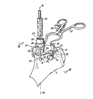
Fig. 2 is a perspective view of a preferred embodiment of the drill
guide instrument a~cording to the invention, which is mounted in
drill guide position on a cut end surface of a femoral collum.
Fig. 3 is a lateral end view taken along the line III-III in Fig. 2, a po-
sitioning member of the instrument having been removed for the
sake of clarity.
15 Fig. 4 is a lateral side view taken along the line IV-IV in Fig. 3, in-
cluding the positioning member.
Fig. 5 is a perspective view of a testing and control device for use in
association with the instrument shown in Figs 2-4.
20 Detailed description of a preferred embodiment of the invention
In order to illustrate the advantages of the present invention, refer-
ence is first made to Fig. 1, which illustrates a hip joint prosthesis of
the type disclosed in W093/ 16663. The prosthesis comprises a cy-
lindrical first fixture part 1, and a plug-like second fixture part 2
25 carrying a ball or caput 3. The first fixture part 1 is made in several
versions of different length, whereas the plug-like second fixture part
2 is made in several versions of different diameter.
The first fixture part 1 has been fitted into a bore 4, which has been
30 drilled longitu~lin~lly through the cancellous bone of the femoral col-
lum 5 along a drill axis B-B by me~ns of a drill tool (lefel~llce nu-
meral 24 in Fig. 2) having a diameter colles~ollding to that of the
first fixture part 1. The plug-like, second fixture part 2 has been fit-
ted into a cylindrical recess 6 cut in the cancellous bone of the col-
CA 02219116 1997-10-24
WO 96/36285 PCTI~G~I90
lum 5 so as to be co~xi~l with the drilled bore 4. The cylindrical re-
cess 6 has been cut longitudinally along the drill axis B-B in a di-
rection away from the head 8 by me~ns of a rotary millin~ tool (not
shown). The millin~ tool is av~ hle in several sizes, each corre-
5 sponding to a specific diameter of a plug-like, second fixture part 2,
and comprises an elorl~te guide el~mer-t to be inserted in and
guided by the drilled bore 4.
The plug-like, second fLxture part 2 is delimited by a circumferential
10 flange 7 limiting the insertion into the recess 6, the flange 7 abutting
~g~inst a cut end surface 11 which defines a cutting plane P, along
which the head 8 of the collum 5 has been removed. Reference is
made to W093/ 16663 for further details of this prior-art prosthesis
shown in Fig. 1 and the anchorage thereof.
In Fig. 1, the orientation of the fLxture parts 1 and 2 relative to thecollum 5, and especially the cortical bone 10, differs from what has
previously been disclosed in W093/ 16663. More specifically, the
plug-like, second fixture part 2 firmly engages, along its entire
20 length, the cortical bone 10 in a specific area 12 located along the
medial aspect of the transition zone between the femoral collum 5
and the femoral shaft 9. Since the overall object is to m~ximise the
support for the fixture part 1, 2 without penetrating the cortical
bone 10, the area 12 of the cortical bone 10, which is relatively thick
25 as illustrated in Fig. 1, is advantageously used for en~ in~zi and
supporting the plug-like, second fixture part 2.
Thus, in order to ensure strong anchorage of the prosthesis, both
the orientation and the position of the drill axis B-B are preferably
30 established with a high degree of accuracy during the drilling opera-
tion, since the bore 4 is subsequently used as guide ~h~nnel for the
milling tool when cutting the recess 6 in the c~ncellous bone of the
collu~n 5, as stated above. Should the oriPnt~tion and/or the posi-
tion of the drill axis B-B be incorrect during the drilling of the bore
35 4, the cylindrical periphery of the cut recess 6 will either (i) be en-
tirely or partly spaced from the adv~nt~~eous area 12 of the cortical
CA 02219116 1997-10-24
W 096/36285 PCTISE9~ 190
bone 10, resulting in no or only partial anchorage of the plug-like,
second fixture part 2 in the cortical bone 10, especially in the advan-
tageous area 12, or (ii) be displaced towards the cortical bone to
such an extent that the latter is penetrated, either by the recess 6 or
5 by the plug-like, second fixture part 2.
As to the risk of penetrating the cortical bone, the situation is com-
plicated due to the fact that the collum 5 is normally funnel-shaped
adjacent to the cutting plane P, as most clearly illustrated in Fig. 3,
10 in which a dashed line N indicates the narrowest part 13 of the col-
lum 5. Due to the funnel-shape of the collum 5, correct positioning
of the drill axis B-B relative to the collum 5, i.e. correct positioning
of the point of intersection of the drill axis B-B and the cutting plane
P, cannot be determined on the basis of the profile section of the cut
15 end surface 11, since it is the size of the na l~west part 13 that de-
termines the ma7~imum permissihle size of the millin~ tool to be
used, and hence the m~ximum permissible diameter of the plug-like,
second fLxture part 2.
20 In Fig. 1, the cutting plane P has been so chosen as to make a pre-
determined cutting angle ~c with the femoral shaft 9, the longitudi-
nal main direction of which is identified by a straight line A-A, and
be located at a predetermined cutting level Lc v.~ith respect to the end
of the head 8. Resection of the head 8 along such a well-defined cut-
25 ting plane may preferably be performed by me~n~ of a cutting guideinstrument as disclosed in the above-mentioned SE 9501828-9.
Referring now to Figs 2-4, the structure and the use of the preferred
embodiment of the drill guide instrument according to the invention
30 vrill be described below, like parts in Fig. 1 and Figs 2-4 bearing like
reference numerals.
Generally, the instrument according to thesinvention coll~l;ses a
drill guide 20 having a base member 21 and a po~itioning member
35 22 connected to the drill guide 20. In the preferred embodiment
shown, the drill guide 20 is in the form of a tubular cylinder, the in-
CA 02219116 1997-10-24
W 096/36285 PCT/SE96/00490
ner periphery of which defines a guide f~h~nnel 23 for receiving and
g~ ling a drill tool 24 along the drill axis B-B. In Fig. 2, the drill tool
24 is a trephine, but any other drill tool may also be used. The base
member 21 of the drill guide 20 is in the form of a plate having an
plane abutment surface 25 CCIv~ g essentially the entire cut end
surface 11. One end 26 of the cylinder 20 is fixedly connected at
right angles to the opposite surface 27 of the abutment plate 21,
which is provided with a through hole (not shown) coinciding with
the guide channel 23 of the cylinder 20.
The positioning member 22 is an exch~ngeable part of the drill guide
instrument and comprises a cylindrical connection sleeve 28, which
fits loosely over the cylinder 20 and is provided with two essentially
U-shaped positioning arms 29. In use, the positioning arms 29 ex-
tend from the connection sleeve 28, beyond the base plate 21 and
towards the collum 5, as shown in Figs 2 and 4. The U-shaped posi-
tioning arms 29 are essentially orthogonal and extend in respective
radial planes of the drill axis B-B. The distal ends of the positioning
arms 29 form ablltment ends 30, both of which are to be brought
into contact with the periphery of the collum 5 at the narrowest por-
tion 13 thereof, as in~lic~ted by the dashed line N in Fig. 2.
The preferred embodiment of the instrument comprises a set of ex-
ch~ng~eable positioning members 22, each having a connection
sleeve 28 with two positioning arms 29. The positionin~ members 22
of the set differ only in radial distance, as measured from their
abutment ends 30 to the centre axis of the connection sleeve 28. In
other words, the two abutment ends 30 and the centre aXis of the
connection sleeve 28 define circles of different diameters for each of
the positioning members 22 of the set. As an ~x~mple, such a set
may comprise four different positioning members 22, co~les~onding
to diameters of 16 mm, 17 mm, 18 mm and 19 mm. Fig. 5 illustrates
a control device comprising a cylindAcal shaft 31 and a stepped
conical base 32 and adapted to veAfy that the abutlllent ends 30 of
each po!sitioning Inemher 22 of such a four-member set are located
CA 02219116 1997-10-24
W 096/36285 PCT/SE~r'~19
at the correct distance from the centre axis of the connection sleeve
28.
F'igs 2 and 3 illustrate a situation in which a positioning member 22
of size n 18" (diameter = 18 rnm) has been selected, after the size of
the na"o~e:~t portion 13 of the collum 5 had been measured at N to
be about 24 mm. In order to obtain, say, a 3-mm safety margin for
the thickness of the cortical bone 10 at the narrowest portion 13 of
the collum, the diameter of the plug-like, second fi~ture part 2
should be selected to be 18 mm. Thus, by selecting a positioning
meml~er 22 of size "18", the drill axis B-B will be located at a mini-
mum distance of 18 mm/2 = 9 mm from the outer periphery of the
narrowest portion 13 of the collum 5. In this ~mple, the recess 6
for the plug-like fixture part 2 may be cut with a milling tool having
a diameter of 18 mm or slightly less, depen-ling on whether the plug-
like, second fLxture part 2 will remove any further bone tissue when
inserted in the recess 6.
In the preferred embodiment of Figs 2-4, the base plate 21 is
clamped ~g~inst the cut end surface 11 of the collum 5 by means of
two pivotable jaws 33. As illustrated most clearly in Fig. 3, each jaw
is p*otably connected to the base plate 21 at 34 for pivotal move-
ment in a plane perpendicular to the base plate 21. The jaws 33
colll~lise co-operating, toothed engagement ends 35, which can be
clamped ~g~in~t the collum 5 by forcing apart the opposite ends 36
with the aid of a separate hand-held cl~mpin~ tool 37 having con-
ventional means 38 for locking the tool in a clamped position. The
above-mentioned funnel shape of the collum 5 in combin~tion with
the pivotal movement of the jaws 33 will also effect clamping of the
base plate 21 downwards in Fig. 3 ~g~inst the cutend surface 11, in
order to ensure correct orientation of the cylinder 21 relative to the
cutting plane P.
The following steps are to be taken when using the above drill guide
instrument. After resection of the head 8 from the collum 5, the size
of the nal~uwes~ portion 13 of the collum 5 is measured. The posi-
CA 02219116 1997-10-24
W 096/36285 PcTl~h~G~ 9o
tion of the narrowest portion 13 may be marked by a line (N). Based
on this measurement, a positioning member 22 corresponding to a
collvellient size of the plug-like, second fixture part 2 is selected for
mounting on the cylinder 20. Thereafter, the abutment surface 25 of
5 the base plate 21 is brought into engagement with the cut end sur-
face 11 of the collum 5. The positioning member is manually dis-
placed along the cylinder 20 from the base plate 21, as illustrated in
Fig. 4, to a position in which the abutment ends 30 of the position-
ing arms 29 are on a level (at line N) with the narrowest portion 13.
10 How~vel, the indication line can be dispensed with, since the nar-
rowest portion 13 of the collum may easily be located by displacing
the positioning member 22 along the cylinder 20 while constantly
urging the two abuLlllent ends 30 into contact with the periphery of
the collum. Preferably, the connection sleeve 28 is rotated about the
15 cylinder 20 to an angular position in which the abutment ends 30 of
the arms 39 are at equal angular distance from a plane of symmetry
of the collum, as indicated by a dashed line L in Fig. 2. The drill axis
B-B being now correctly orientated and positioned, the whole instru-
ment is temporarily fixed to the collum 5 by me:~ns of the jaws 33
20 and the clamping tool 37. The drill tool 24 can now be received in
and guided by the drill ch~nnel 23 for drilling the bore 4 longitudi-
nally through the collum 5, whereupon the drill guide instrument is
removed. Finally, the recess 6 is cut in the cancellous bone as de-
scribed above, using the drilled bore 4 as guide channel for a milling
25 tool.
Several mo~lifi~tions of the embodiment described above are con-
ceivable within the scope of the appended ~l~im~ For ~x~mrle, the
drill guide may be formed by a number of coaxial rings forming a
30 guide ch~nnel for a dAll tool. Furthermore, the dAll tool may be
formed integral with the instrument, and in that case the structure
of the dAll guide may rliffer essentially from that of the embo~liment
shown in the Figures. In a more simple embodiment, the positioning
member may be fixedly connected to the dAll guide. As to the base
35 member, other alternatives than a plate could be envisaged, e.g.
some form of tripod arrangement for oAentin~ the dAll guide relative
CA 02219116 1997-10-24
W 096/36285 PCT/SE9GJ'~0190
12
to the cut end surface. Finally, the abullllent ends 30 of the posi-
tioning member could be in the form of a continuous ring abu~ting
s~in~:t the collum along the line N.