Note: Descriptions are shown in the official language in which they were submitted.
CA 02219264 1997-10-23
- PATENT
3251-03-00
WEIGHT-SUPPORTED ADJUSTABLE MIXING AND DISPENS:~TG GUN
FOR TWO CHEMIICALLY REACTIVE MATERIALS
Field of the Invention
This invention relates to an apparatus for mixing and dispensing two
chemically
reactive fluids and, more particularly, to an easy-to-use, fully weight-
supported in an operative
position, and multiply pivoted hand-operated mixing and dispensing gun,
especially suited to
be used for applying two-component :polysulfide sealants to insulating glass
units.
Back~~ourad of the Invention
Two-component fluids, such ;~s reactive sealants or adhesives, are made up of
two
separate materials, that are initially stoned in separate containers, but
which when intermixed,
react chemically with one another to eventually form the desired hardened
sealant or adhesive
product. For example, polysulfide sealants that are used in the fabrication of
insulating glass
units, such as windows and doors, in order to provide seals against moisture
intrusion and heat
loss, include a first viscous curable poilymeric material, such as a
polysulflde base resin, and
a second viscous material, such as a cati~lyst or hardener for the base resin.
After intermixing,
the reactive fluids are often dispensed from a hand-held dispensing gun and
applied to the work
piece in a bead containing the desired amount of intermixed components.
A variety of systems have been employed for mixing and dispensing two-
component
reactive fluids. In earlier systems, it is common to pump the two fluids from
their individual
storage vessels through two flexible hosfa, that are supported on an elevated
pivoted arm, into
a motionless premixer that freely hangs down in air from the pivoted arm.
Usually, the
flexible hoses are attached by rigid connections, such as with standard
fittings, to the inlet of
- _ CA 02219264 1997-10-23
PATENT
3251-03-00
a motionless premixer. The two fluids are then directed through the premixer
for
homogeneous mixing prior to being dispensed. Next, the mixed components ;are
directed from
the premixer outlet to the inlet of a generally unsupported hand-held
dispensing gun that freely
hangs down from the premixer to the floor. Usually, a single flexible hose:
rigidly connects
the premixer outlet to the dispensing gun inlet. The dispensing gun tyyically
includes a
dispensing valve in the body of the gun actuated by a finger trigger on the
han d grip of the gun
for the operator to control the mixed fluid flow to an outlet nozzle. The hand-
held dispensing
gun when not in use is usually placed on a hook suspending down from the
pivoted arm, so
that the gun does not drag on the floor when not in use.
The use of premixers makes these dispensing systems much mare complex and
cumbersome, and also results in waste in the portion of the fluids left in
the, premixer or gun
after mixing, particularly in instances where the mixed fluids are not
immediately dispensed.
Since the mixture tends to cure and take a set when brought together, the
mixed material that
remains in the equipment is not only wasted, but also if not purged quickl~r
from the system
with either solvent from a separate line or one of the unmixed components
passed alone
through the system, it necessitates taking the premixer and gun apart for
expensive and time-
consuming solvent cleaning to clear the obstructed flow passages. The cleaning
solvents or
unmixed purged components used to clear the system must also be disposed of as
hazardous
waste, which leads to increased operating costs.
Moreover, in such earlier systems, the dispensing gun and premixer .are too
heavy and
bulky, and, as a result, movement and positioning of the gun are difficult and
cumbersome.
Also, the rigidity of the connections established between the flexible hosing
and the premixer
and dispensing gun adds to the difficulty that the operator experiences in
maneuvering the gun.
Accordingly, it is necessary for the operator handling the dispensing; gun to
expend
considerable energy in manually supporting and maneuvering the dispensing
~;un, premixer and
attached hoses. As a consequence, tile operator commonly experiences fatigue,
muscle strain
and other physical maladies. Also, the resulting difficulty in properly
positioning the
dispensing over the work piece gun exactly as desired causes improF~er or
incomplete
-2-
CA 02219264 1997-10-23
PATENT
3251-03-00
application of the fluid onto the work piece, adversely affecting the quality
of the work
product.
In another type of dispensing; system that has been proposed, the afi~resaid
assembly
is rearranged such that the motionless mixer is placed at the outlet of the
hand-held dispensing
gun. In such a system, the two separate fluid components are fed individually
to the gun,
passed separately through valued ports in the gun that are controlled by the
operator actuating
the finger trigger on the hand grip of the gun, and finally brought into
contact with each other
in the static mixer attached to the outlet nozzle of the gun. The static mixer
is usually attached
to the gun outlet in a removal manner, and is designed to be disposed and
replaced after use,
in order to avoid the necessity of wasteful and expensive purging and cleaning
of any part of
the gun which comes into contact with mixed fluid components. The static mixer
includes a
rather elongated body from which i:he mixed material is directed to an outlet
nozzle at the
remote end of the mixer.
One of the problems with such an arrangement is that elongated static mixer
body
causes the dispensing nozzle to be positioned a great distance away from the
actuating trigger
located on the hand grip of the gun, which arrangement makes the ~;un
difficult and
cumbersome to use. The intricacies of the parts, including channels and
grooves, in which the
reactive material is to be deposited requires the gun to be positioned with
yrecision over the
work piece. Improper positioning during application adversely affects the
qu;~lity of the work.
The dispensing nozzle, however, being positioned so far away from the
actuating trigger on
the hand grip where the operator holds the gun causes the operator to lose
control of the nozzle
during application.
Also, the gun body is too heavy, bulky and unbalanced, which tends to force
the
dispensing nozzle to move out of position, either upwardly or downwardly,
during application.
The rigidity of the flexible hose connections to the gun adds to the
difficulty in
maneuverability of the gun. The operator, therefore, has to expend
considerable energy to not
only manually support and guide the gun and the attached hoses into position,
but also once
in position, he has to expend a significant amount of additional energy evf,n
to maintain the
-3-
- CA 02219264 1997-10-23
PATENT
3251-03-00
nozzle in the proper position. The exb~nsive manual movement and effort
required to support,
maneuver and position the gun and attached hoses commonly causes the operator
to experience
strain and fatigue in this system as well.
U. S . Pat. 4, 643, 336 to Mandeville et al. discloses a mixing and dispensing
gun
including a hand-held gun body having a hand grip, an actuating trigger on
th~~ hand grip, and
spaced inlets in the gun for separately receiving two components of a reactive
fluid from
flexible hoses. The flexible hoses are: pivotally suspended from a pivoted
arm, yet the hoses
are rigidly connected with standard fnttings to the gun inlets. A dispensing
~ralve is included
in the gun and is actuated by the trigger, and a vertically, rather than
horizontally, elongated
static mixer is threadedly attached to the gun, with the mixer being
interposed between the
dispensing valve and outlet nozzle of the gun. The vertically elongated static
mixer reduces
the overall length of the gun and, consequently, brings the dispensing nozzle
and gun closer
to the work surface to improve the control of fluid placement during
open~tion, as well as
making the gun less cumbersome.
However, the mixing and dispensing gun is not weight supported on the pivoted
arm
in an operative position and hangs freely down therefrom to the floor. The gun
is also rigidly
connected to the flexible hoses that deliver the two components into the gun.
For the same
reasons as previously discussed, the operator using the system of MandevillE~
et al. must still
exert considerable effort to manually support and maneuver the gun and
attached hoses into
the proper position over the work surface.
U.S. Pat. 5,330,106 to Braun, Jr. discloses a hand-held mixing anc! dispensing
gun
having the two flexible supply hoses attached to the gun by rotatable swivel
connectors to
facilitate ease of movement of the gun relative to the flexible hoses. A
swivel connector is
rotatably mounted on each end portion of a cylindrical distributor that is
rigidly attached to the
rear of the gun remote from the valued outlet nozzle. The swivel connectors
include separate
inlets connected to the two supply hose ends, with the swivel inlet; also
being in
communication with separate distributor conduits which, in turn, communicate
with the
separate conduits attached to the disF~ensing nozzle of the gun.
-4-
_ CA 02219264 1997-10-23
PATENT
3251-03-00
Since both hoses are connectedl to the distributor with the use of swivels
rotatable about
a common axis, improved flexibility between the gun and hoses is achieved, and
pivoting the
dispenser gun relative to the hoses is said to require less effort.
Furthermore, the swivel
connections between the hoses and ,gun are said to reduce the hose weight
imposed on the
dispenser gun. In another embodiment of Braun, Jr. , the distributer is
rotatably connected to
the gun having a pivot axis perpendicularly disposed to the common hose swivel
axis. The
distributor in this arrangement may :itself swivel relative to the gun, which
is said to further
enhance the flexibility and allow thr~~ dimensional adj ustment of the gun.
In Braun, Jr. , however, the gu,n remains unsupported and generally h~mgs down
freely
from the flexible hoses, that are supported on the dispensing system, towards
the floor. The
operator, therefore, must still exert considerable effort to manually weight
support and
manually maneuver the gun and attached hoses to the proper position over the
work surface.
Furthermore, properly aiming the g;un of Braun, Jr. and manually holding the
gun in the
proper position during application would be expected to be difficult, sina~
with the added
flexibility, the bottom heavy gun would be expected to rotate downwardl3~,
making nozzle
control and proper positioning difficult.
What is needed is an improved apparatus for mixing and dispensing; two-
component
reactive fluids that includes a gun which will both mix and dispense the
fluids, which is less
bulky and cumbersome than prior systems, which produces less waste and what
little waste it
produces is readily removed, which will bring the hand operated trigger closer
to the outlet
nozzle so that the operator can hold th.e gun closer to the point of
application for better control
of fluid placement, which is fully weight supported in an operative position
arid, consequently,
has less total weight than prior systems for ease of use and reduction in tree
occurrences of
operator fatigue and muscle strains, and which is pivoted at multiple
locati~~ns for improved
flexibility and maneuverability.
-5-
CA 02219264 1997-10-23
PATENT
3251-03-00
It is an object of this invention, therefore, to provide a new and improved
two-
component mixing and dispensing system including a fully mechanically weight-
supported in
a ready-to-use position and multiply pivoted mixing and dispensing gun.
It is another object of this invention to provide a mixing and dispensing; gun
that is fully
mechanically weight supported in an operative position and balanced, in order
to reduce the
total weight of the gun and make thc: gun less cumbersome and easier to
operate.
It is yet another object of this invention to provide a mixing and di;~pensing
gun that
passes two reactive fluids separately through the gun and has an elongated
disposable static
mixer placed on the outlet of the dispK~nsing gun, in order to reduce the
amount of mixed waste
during start-up and shut-down, and eliminate essentially all solvent cleaning
or base purging
during shut-down, since the static mixer may be discarded after use.
It is still another object of this invention to provide a mixing and
dispensing gun with
a hand-held actuating trigger placed on the elongated end of the static mixer'
tube, in order to
reduce the distance between the operator's hand that holds the hand trigger
and the dispensing
outlet nozzle for better control of fluid placement on the work surface.
It is still another object of this invention to provide a mixing and
dispensing gun with
reactive fluid feed lines and support lines being pivotally attached to the;
gun in multiple
locations for improved flexibility arid maneuverability and reduced line
lcinking.
In accomplishing these and other objects, the invention resides in a mixing
and
dispensing system for two chemically reactive fluids, which is characterized
by: a pump means
for supplying two chemically reactive fluids separately through two flexible
hoses; an
elongated pivoted arm for pivotally supporting the two flexible hoses z~bove a
generally
horizontal plane with a front end of each of the flexible hoses hanging belnw
the pivot arm,
the pivoted arm being rotatable about a generally vertical pivot axis; a
mixing and dispensing
gun including a body having two spaced inlets on opposite sides of .the gun
bndy for separately
receiving the two fluids from the two flexible hoses, and two spaced outlet;
on a front of the
gun body for separately dispensing the two fluids from the gun, a dispensing
valve in the gun
-6-
CA 02219264 1997-10-23
PATENT
3251-03-00
body for controlling the flow of the two fluids out through the two outlets,
with the front ends
of the two flexible hoses being separately pivotally attached to the two
spaced inlets with two
swivel connectors having flow channels defined therein, the swivels being
rotatable about a
common generally horizontal pivot axis and in flow communication with the
flexible hoses and
spaced inlets in all rotative positions; a static mixer including an elongated
mixing tube having
an inlet at one end connected to the two outlets of the gun body and an
dispensing outlet nozzle
at the opposite elongated end, and statiionary mixing elements disposed in the
mixing tube; an
actuating trigger positioned on the ;>tatic mixing tube in close proximity t~~
the dispensing
nozzle outlet end of the mixing tube for actuating the dispensing valves in
the: gun body; and,
means for weight supporting the bot3y of the mixing and dispensing gun above a
generally
horizontal plane in an operative positicm, the weight support means extending
i:rom the pivoted
arm and being pivotally attached to the: top of the gun body, with the support
means including
a swivel being rotatable about a generally vertical pivot axis, the pivot axis
being substantially
perpendicular to the common generally horizontal pivot axis of the swivel
connectors.
The various objects, features and advantages of the invention will become more
apparent from the following description.
Brief Descriytion of the Drawings
There are shown in the drawings certain exemplary embodiments of the invention
as
presently preferred. It should be understood that the invention is not limited
to these
embodiments and is capable of variation within the spirit and scope of the
appended claims.
With this description of the invention, a detailed description follows with
reference to
the drawings, in which like referencE: numerals denote like elements, and in
which:
FIG. 1 is a perspective view oiP a mixing and dispensing system embodying the
weight-
supported, mufti-pivoted mixing and dispensing gun of the present invention;
FIG. 2 is side view of the mi~u~g and dispensing gun of the present imrention,
with the
gun being tilted on its side for clarity;
. _ CA 02219264 1997-10-23
PATENT
3251-03-00
FIG. 3 is a fractional exploded view, partly in section, of the mixini~ and
dispensing
gun of the present invention;
FIG. 4 is a side sectional view of an exemplary swivel connector thstt can be
used to
establish multiple pivotal flow connections in the mixing and dispensing gun
of the present
invention;
FIG. 5 is a front view, partly 'in section, of an exemplary balancer that can
be used to
weight support, in an operative position, the mixing and dispensing gun of the
present
invention;
FIG. 6 is a side sectional view of the balancer of FIG. 5 taken alon~; line 6-
6;
FIG. 7 is a schematic of an exemplary air flow circuit for deaetivatin;g the
mixing and
dispensing gun of the present inventiion; and,
FIG. 8 is a schematic of an exemplary air flow circuit for activating the
mixing and
dispensing gun of the present invention.
Detailed Descriytion of the Preferred Embod'ments of the nvention
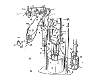
Referring to FIG. 1, the dispensing system embodying the invention is
generally shown
as 10 and includes supply vessels 12 and 14 respectively housing two
chemically reactive fluids
that ne~cl to be metered and mixed before dispensing, such as a polysulfide
lass resin 16 and
a catalyst 18. The dispensing system 10 also includes pumps 20 and 22 for the
resin and
catalyst, respectively, such as positive: displacement pumps operated with air
motors driven by
compressed air. The pumps 20 and 22 respectively direct the fluids from the
supply vessels
12 and 14 through separate flexible hoses 24 and 26 to separate inlets of
manifolds 28 and 29
which contain separate flow ports 30 and 32 (shown in phantom) for both the
base resin and
catalyst.
The catalyst hose 26, in particular, communicates with a standard metering
cylinder 34,
such as a positive displacement pump, prior to entering the catalyst inlet in
the manifold 29.
The metering cylinder 34 is used to provide the correct mix ratio of resin t~~
catalyst flowing
through the manifolds 28 and 29. ,As shown in FIG. 1, a cylinder linkage: 36
is attached to
_g_
,. CA 02219264 1997-10-23
PATENT
3251-03-00
both the resin pump 20 and the catalyst metering cylinder 34. Upon every
stroke of the resin
pump 20, the metering cylinder 34 pivots a set distance which draws a properly
proportioned
amount of catalyst into the catalyst part 32 in the manifold 29, as the
desired. amount of resin
is simultaneously pumped separately into the resin port 30 in the manifold 28.
Flexible hoses 40 and 42 for the resin and catalyst, respectively, are
separately attached
to separate outlets in the manifolds 28 and 29. 1'he flexible hoses 40 and 42
eventually direct
the fluids individually to a mixing aJnd dispensing gun 44.
Referring now to FIG. 2, the flexible hoses 40 and 42 are sup~p~orted
generally
horizontally above the floor 46 on a pivoted arm or boom 48 that is rotatatbly
attached by a
pivot joint 50 to a ram post 38 associated with the resin pumping unit. The
boom 48 is
rotatable about a generally vertical pivot axis. The boom 48 extends outwardly
a substantial
radial distance from the ram post 38 and the resin pumping unit in order to
provide enough
clearance for an operator to adequately maneuver the dispensing gun 44.
The flexible hoses 40 and 42 resting upon the boom 48 are attached to a
manifold block
52 mounted on top of the boom 48 generally at its outermost end. The manifold
52 includes
separate flow ports 54 and 56 (shown in phantom) for the base resin and
catalyst, respectively.
The resin flow port 54 contains about a 90~ upward bend, so that the resin is
directed to exit
at the top of the manifold 52. A standard swivel joint or swivel connector 58
is rotatably
mounted around a generally vertical rotational axis to the outlet of the
manifold resin port 54
at the top of the manifold 52.
An exemplary swivel connE:ctor 58, as shown in partial section in FIGS. 2 and
4,
generally includes an elongated cylindrical swivel tube 60 that is suitably
connected to the
outlet of the resin port 54. The tube 60 includes an inlet port 62 at the end
connected to the
resin port 54 and radial ports 64 disposed around the circumference of the
tube at a selected
distance along its length. The portion of the tube having the radial ports E4
is rotatably and
sealingly housed in an outer swivel sleeve 66. The sleeve 66 generally
surrounds the radial
ports 64 and contains an outlet port 68, which is generally perpendicular tn
the inlet port 62
and alignable with at least one of the radial ports 64 in all rotative
positions, thereby allowing
-9-
CA 02219264 1997-10-23
PATENT
325l-03-00
open flow communication between the inlet port 62 and outlet port 68 when the
swivel sleeve
66 is rotated in every pivotal position.
Referring again to FIG. 2, a generally horizontally elongated pivoted arm 70
having
an internal resin port 72 (shown in phantom) extending therethrough is
suitably connected to
the outlet port 68 of the swivel connector 58. The pivoted arm 70 extends
outwardly a
shortened radial distance from the remote end of the boom 48 and is pivotal
around the
generally vertical swivel axis provided by the swivel connector 58, in order
to allow the
operator to further extend the dispensvng gun 44 away from the resin ram post
38 and pumping
units, providing additional room for the operator to maneuver the gun,. It
should be
understood that the manifold and swivel connector may be arranged so that. the
pivoted arm
is positioned below rather than above the boom to allow complete rotation of
the pivoted arm
about the pivot axis.
Suitably attached to the outlet ~of the catalyst port 56 which extends axially
through the
manifold 52 is a second swivel connector 74 having generally perpendicular
inlet and outlet
ports 76 and 78. The swivel connector 74 is pivotal around a generally
horizontal rotational
axis. The swivel connector 74, as shown, is generally of the same
configuration as that of the
aforesaid swivel connector 58. A flee;ible hose 80 for the catalyst is
suitably connected to the
outlet port 78 of the swivel connector 74 and is supported upon the pivoted
arm 70 along its
length. The swivel connector 74 prevents lcinlcing of the catalyst hose 80
during rotation of
the pivoted arm 70 as an operator positions the dispensing gun 44.
A flexible hose 82 for the resin is suitably connected to the resin outlet
port on the
outermost extension end of the pivoted arm 70. The flexible resin hose 8:? and
the flexible
catalyst hose 80 hang freely down from the pivoted arm 70 towards the flobr
but preferably
do not reach the floor. Each hose 82 and 80 is individually attached through
:swivel connectors
84 and 869 respectively, to separate rESin and catalyst inlet ports 88 and 90
on opposite lateral
sides of the dispensing gun 44. The swivel connectors 84 and 86 are generally
of the same
configuration as that of the aforementioned swivel connectors 58 and 74. The
swivel
connectors 84 and 86 are rotatable around a common generally horizonti~l
rotational axis,
- 10-
~
. CA 02219264 1997-10-23
PATENT
3251-03-00
which improves the pivoting of the dispensing gun 44 relative to the flexible
hoses 80 and 82
and dramatically reduces the effort required to maneuver the gun.
The top portion of the dispensing gun 44 is suspended above the floor 46 with
a
tensioned line 92 that is used to counter balance and fully weight-support the
dispensing gun
44 in an operative position above the floor 46, thereby eliminating the need
fir an operator to
manually weight support a heavy and cumbersome dispensing gun. The tension and
length of
the line 92 can both be adjusted using a standard tool balancer 94 that is
suitably mounted to
the pivoted arm 70 and from which the line 92 extends. The tool balancer 94 is
preferably
mounted to the arm 70 such that it is pivotal up to about 30~ from a generaly
vertical axis.
The lower end of the balancer line 92 is looped and pivotally connected to the
top of the
dispensing gun 44.
Referring now to FIGS. 5 and 6, an exemplary tool balancer is shown. With this
tool
balancer, the amount of overhang of the line 92 can be adj usted in order to
set the initial
elevation of the gun 44 above the floor 46 by moving up and down a movable
stop 93 that is
releasably secured to the line 92. The line 92 is also spring tensioned to
supF~ort the gun 44 at
the selected elevation without having the line descend towards the floor from
the weight of the
gun. To adjust the line tension, a tension knob 95 is rotated in a clockwise
direction which
action tensions the main spring in the; balancer. The balancer is also
equipped with a tension
release button 97 to selectively release tension in the line 92.
Referring again to FIG. 3, a snap swivel 96 is used to pivotally corm ect the
top of the
dispensing gun to the tool balancer line 92. The snap swivel includes an upper
snap clip 98
and a lower ring 100. The snap clip 98 and ring 100 are rotatably connected
together by a
pivot connecting rod 102 and are rotatable around a generally vertical pivot
axis. The upper
snap clip 98 is connected to a tool clip ring 103 which is relea.sably
attached to the looped end
of the balancer line 92. The lower ring 100 is releasably attached 'to a
hanger and plug
combination 104 that is threadedly attached to the top of the dispensing gun
4~~. The pivot axis
of the snap swivel 96 is arranged to be substantially perpendicular relative
to the common
-11-
CA 02219264 1997-10-23
PATENT
3251-03-00
swivel axis of the two swivel conne~~tors 84 and 86 for three dimensional
movement of the
gun.
The dispensing gun 44 in the aforesaid arrangement is not only entirely weight-
supported in an operative position, which allows the operator to maneuver tile
gun with very
little effort, but also is adj ustable im height and along multiple pivot axes
to allow three
dimensional pivoting of the gun for better control of fluid placement on the
~~rork surface and
reduced line kinking. It should be understood that other methods may b a used
to weight
support and balance the gun in an operative position as well, such as
counterbalancing the gun
with a spring supported on the pivoted arm and the like.
The dispensing gun 44 can be of any standard construction as is well known in
the art
for mixing and dispensing two-component reactive fluids. It is preferred that
the gun allow
f~ khe ~tecor~ponen~ tote-fed individually through the gun, passed sE:parately
through
valued outlet ports that are controlled by an actuating trigger, and brought
into contact with
each other upon reaching an elongated mixing chamber attached to the valued
outlet ports of
the gun, with the mixing chamber having an outlet nozzle from which the
rr~ixed components
are discharged. Although the dispensing gun will be described below with
reference to a
pneumatic or air actuated gun, the present invention is not limited to this
exemplary
embodiment.
Referring now to both FIGS. 2 and 3, an exemplary dispensing gun 44 as shown
includes a generally rectangular body 106 having separate resin and catalyst
inlet ports 88 and
90 on opposite sides of the body which, respectively, lead to separate
elongated fluid passages
108 and 110 extending in the body. 'The two fluid components are passed
separately along the
passages 108 and 110 through two valued outlet ports 112 and 1l4 for
controlling the
dispensing of the two fluids separately through a divided outlet opening 116.
The dispensing valves controlling the valued outlet ports 112 and :l14 can be
of any
standard construction as is well known in the art. The valves as shown are air
trigger actuated
valves and include interconnected movable valve needles 118 and 120 which in
the normally
closed position respectively urge snuff rings I22 and 124 against valve seats
I26 and I28 in
- 12-
CA 02219264 1997-10-23
PATENT
3251-03-00
order to close the seats and prevent fluid flow past the valued outlet ports
112 and 114 and out
through the divided outlet 116.
'The movement of the valve needles 118 and 120 and, thus, the opening and
closing of
the valued outlet ports 112 and 114 are controlled by an air piston 134 driven
by compressed
air that as supplied into the body of the gun. The compressed air is directeii
into one of two
air chambers 130 and 132 in the top rear of the gun body, which respectively
control the
opening and closing of the valued outlet ports. 1fie open and close air
chambers 130 and 132,
respectively, are sealingly divided from one another with a movable air piston
134 which
interconnects the valve needles 118 and 120. Air pressure directed against the
head of the
piston 134 in one of the chambers causes movement of the piston and tree
interconnected
needles, consequently either opening or closing the valued outlet ports 112
and 114. When
opened, the valve needles I18 and ~~20 allow for the flow of the respective
fluids from their
separate passages 108 and 110 through the divided outlet l16 in order to mix
together in a
standard motionless or static mixer 136 that is attached to the divided gun
outlet.
IS The passage of air selectively into one of the two chambers I30 andl I32 to
cause the
opening and closing of the air actuated valves is controlled by pivoting an
actuating air trigger
138, as will be described more fully described hereinafter.
The static mixer I36 is threadedly attached to the divided outlet 116. The
static mixer
136 includes an elongated spiral mixer tube 140 and running substantially th.e
entire length of
the spiral mixer tube 140 are spiral mixer elements 142. The spiral mixer
elements 142 are
composed of pairs of helical vanes spiralexi in opposite directions about a
common longitudinal
axis along the length of the spiral mixer tube 140, as is well known in the
a~~t. The pattern of
the spiral mixer elements allows homogeneous swirling and mixing of the resin
and catalyst
as they pass through the length of the spiral mixer tube 140. The st;~tic
mixer 136 is
removably housed in an elongated outer tubular jacket I44 that is threadedly
attached to the
divided outlet l16.
The static mixer 136, including the spiral mixer tube 140 and spiral mixer
elements
142, is preferably molded of an inexpensive plastic material so that after
dispensing, mixed
-13-
- CA 02219264 1997-10-23
PATENT
3251-03-00
and catalyzed resin need not be removed from the tube. Instead of rinsing with
hazardous
solvents or purging with costly unmixed base resin, the static mixer l36 is
removed and set
aside until the mixed material hardens. within the mixer tube 140. After the
material has set,
the tube and static mixer pose no environmental hazard and can simply be
thrown away after
use, thereby eliminating solvent cleaning or base purging and the creation of
costly and
hazardous waste therefrom.
After passing through the static mixer 136, the mixed fluids are directed to
an outlet
nozzle 146 at the outermost end of the outer jacket 144. Dispensing tips 148
having the
desired configuration for the particular application can be threadedly
connected to the single
outlet nozzle 146.
The dispensing gun is activated with a hand-held actuating air trigger 138
that
communicates witha supply ofcom~ryssed air from an air supply is-mounted ~~n
the outlet end
of the outer jacket 144. The air trigger 138 is positioned in close proximity
to the outlet
nozzle 146 and dispensing tip attachment 148 for better control of fluid
ylacement by the
operator. Rather than having the tJ-igger positioned on the body of the gun 44
which is a
substantial distance away from the outlet and dispensing tip, the hand
operated trigger in the
present invention is positioned closer to the outlet nozzle 146 and dispensing
tip 148, which
allows the operator to hold the gun closer to the point of application for
better dispensing
control. lass effort is, therefore, required to properly position and maintain
the gun over the
work surface.
The air trigger 138 can be made of any standard construction. As shown in FIG.
3,
an exemplary air trigger 138 is a 4-way valve which includes a depressible
finger button 150
connect~i to a spring biased valve stem 152 that is movably contained in a
channel 154 formed
in a trigger housing 156. The channen 154 is provided in flow communication.
with an air inlet
port 158 on one side of the housing 156 and two spaced apart air outlet port;>
160 and 162 on
the opposite side. Depending on the. position of the valve stem l52 in the
channel, only one
of the two outlets 160 and 162 at a tune is in open flow communication with
the air inlet port
158, with the other being sealed by spaced apart enlarged snuff rings on the
valve stem. The
- 14-
CA 02219264 1997-10-23
PATENT
3251-03-00
air trigger 138 also includes two spacExl exhaust ports 164 and l66 which are
provided in flow
communication with outlet ports 160 and 162, respectively, and serve to
evacuate air from the
outlet port that is in the sealed position.
Thus, when air is supplied from an air hose through the trigger inlet port
158,
depending on the position of the trigger valve stem 152 through depression of
the finger button
150, the air is directed to flow out onE: of the two outlet ports 160 and I62
and selectively into
either the opened or closed air chambers 130 and 132 in the body of the; gun,
which are
respectively connected to the outlet ports 160 and 162 of the air trigger with
air hoses. It
should be understood that other stand~~rd trigger controlled dispensing valves
for the dispensing
gun can be used as well, such as spring trigger actuated valves or electrical
trigger actuated
valves.
In a preferred embodiment of the present invention, it is desired to exhaust
any volume
of compressed air that is left in the gu.n after the air trigger is released
when the operator wants
to stop dispensing the mixed fluid from the gun. Exhausting of air from tha:
body of the gun
avoids static pressure builds in the air circuit and prevents surges and
overruns of mixed fluid
during start-up of the gun, which is undesirable.
Referring now to FIG. 7, a preferred air flow circuit 170 used four
deactivating the
plural component mixing and dispensing system of the present invention without
static pressure
build is shown. Arrows are used in FIG. 7 to indicate the direction of air
flow through the
circuit. Compressed air 172 enters a main air manifold 174 and flows oul: into
a circuit tee
fitting I76 attached to an outlet on the manifold. Air is directed from the
circuit tee fitting 176
through an air hose 178 to the inlet L58 of the 4-way air trigger 138. The
push button 150 on
the air trigger is ira the undepressed G~ndition so as to allow unobstructed
flow communication
between the air inlet 158 and air outlet I60 in the trigger 138. The 4-way air
trigger 138 sends
the compressed air out of the air outlet 160 through an air hose 180 into the
normally closed
air inlet port 132 in the mixing and dispensing gun 44. The air acts against
the air piston 134
and forces the valued outlet ports a 12 and 114 in the gun body to remain in
their normally
-15-
- _ CA 02219264 1997-10-23
PATENT
3251-03-00
closed positions, which deactivates the gun and stops the reactive fluids in
the fluid passages
108 and 110 of the gun from exiting the divided gun outlet 116.
In the air flow circuit 170, while the mixing and dispensing gun 44 is
deactivated, an
exhaust cycle simultaneously occurs to stop the main air motor 190 that drives
the base resin
pump 20 and remove static pressure build from the air circuit. For this to
occur, compressed
air is also directed from the main air manifold 174 out into a valued port 182
of a standard
pilot valve 184 that is attached to an outlet of the manifold 174. The valued
port is normally
closed by a valve 186, which stops the air from traveling through an air hose
188 into the
master air motor 190 that is used to activate the base resin pump 20. Stoppage
of compressed
air to the air motor 190 causes the base resin pump 20 to stop and eliminates
static pressure
build in the fluid lines 80 and 82 to t:he dispensing gun 44.
Compressed air is also caused to exit the circuit tee fitting 176 through an
air hose l92
into a standard air toggle 194 and is stop therein, since the air toggle is
switched to its closed
position. Air is, thus, not allowed to pass from the air toggle l94 through an
.air hose 196 into
a standard shuttle valve 198, which av- flow, if allowed, would shift the
normally closed valve
200 in the shuttle valve 198 to an opened position and direct air into the p
ilot valve 184 to
cause the opening of the normally closed valve 186 therein, so as to allow
p;~ssage of air into
the air motor l90 in the deactivated condition, which would cause a les~~
desirable static
pressure build up in the fluid lines.
Referring now to FIG. 8, a preferred air flow circuit 202 used for activating
the plural
component mixing and dispensing system of the present invention is shown) Here
again,
arrows are used to indicate the direction of air flow through the circuit.
When the push button
finger trigger 150 is depressed, air is exhausted from air hose 180 through
thc; air exhaust port
164 in the air trigger l38. Simultaneously, compressed air l72 continues to
enter the main air
manifold 174 and flows out into the circuit tee fitting l76. Air is directed
from the circuit tee
fitting 176 through the air hose 178 to the inlet 158 of the 4-way air trigger
138. The push
button 150 on the air trigger is depressed, so as to allow unobstructed flow
communication
between the air inlet 158 and air outlet 162. The 4-way air trigger 138 sends
the compressed
- 16-
a CA 02219264 1997-10-23
PATENT
325l-03-00
air out of the air outlet l62 through an air hose 204 and through a tee
fitting 206 and into the
normally opened air inlet port 130 in the mixing and dispensing gun 44. Th.e
air acts against
the air piston 134 and forces the valued outlet ports 112 and l 14 in the gun
b ody open, which
activates the gun and starts the flow of reactive fluids through the gun
passiiges 108 and 110
and causes the fluids to exit the divided gun outlet 116 into the static mixer
136 and out of the
gun through the dispensing tip 148.
Compressed air is also direct~:d out of the tee fitting 206 through an air
hose 208 into
the shuttle valve 198 and then into the pilot valve l84, which in turn, opens
valve 186 and
allows compressed air from the man air manifold 174 to feed the master air
motor 190,
sending the air motor and base resin Fmmp 20 into motion and causing the
fluids to be pumped
through fluid lines 80 and 82 into the dispensing gun 44. The air toggle 194
again remains in
the closed position.
When it is desired to stop dispensing the mixed fluids from the dispensing tip
148 of
the mixing and dispensing gun 44, the; push button 150 on the air trigger 138
is released. This
causes the air flow pattern to revert back to that shown in FIG. 7. As the
button l50 is
released, air is exhausted from air 'hose line 204 through air the exhaust
port 166 in the air
trigger 138, and air is likewise exhausted from air hose line 188 through air
exhaust port 210
and muffler 2l2 on the pilot valve 1 &4, which eliminates static pressure
build and fluid surges
and overruns when the push button l50 is again depressed.
It should be understood that all individual parts used herein to :Form the
weight-
supported, mufti-pivoted mixing and dispensing gun of the present invention
are readily
commercially available.
The advantages stemming from the present invention include, without
limitation:
1. The dispensing gun is fully mechanically weight supported in an operative
position
and balanced, and, therefore, has less total weight and is less cumbersome to
use.
2. The disposable static min;er placed after the separate flow dispensing gun
reduces
the amount of mixed waste during start-up and shut-down, and requires
essentially no solvent
cleaning or base purging during sihut-down, since no mixed fluids ever pass
through the
- 17-
CA 02219264 1998-09-25
PATENT
3251-03-00
dispensing gun and since the mixer containing the mixed waste may be simply
discarded after
use.
3. The actuating trigger placed on the dispensing end of the elongated static
mixing
tube reduces the distance between the hand held trigger and the di$pensing
outlet nozzle,
allowing the operator to hold the gun closer to the dispensing outlet nrozzle
for better control
of fluid placement on the work surface.
4. The dispensing gun and feed and support lines are pivoted in multiple
locations for
improved flexibility and maneuverability and reduced line kinking.
The invention having been disclosed in the foregoing embodiments and examples,
other embodiments of the invention will be apparent to persons skilled in the
art. The
invention is not intended to be limited to the embodiments and examples, which
are
considered to be exemplary only. Accordingly, reference should be made to the
appended
claims to assess the true spirit and scope of the invention, in which
exclusive rights are
claimed.
- 18-