Language selection

Search

Patent 2219340 Summary

Third-party information liability

Some of the information on this Web page has been provided by external sources. The Government of Canada is not responsible for the accuracy, reliability or currency of the information supplied by external sources. Users wishing to rely upon this information should consult directly with the source of the information. Content provided by external sources is not subject to official languages, privacy and accessibility requirements.

Claims and Abstract availability

Any discrepancies in the text and image of the Claims and Abstract are due to differing posting times. Text of the Claims and Abstract are posted:

  • At the time the application is open to public inspection;
  • At the time of issue of the patent (grant).
(12) Patent Application: (11) CA 2219340
(54) English Title: TRANSVENOUS DEFIBRILLATION LEAD WITH SIDE HOOKS
(54) French Title: CONDUCTEUR DE DEFIBRILLATION PAR VOIE VEINEUSE A CROCHETS LATERAUX
Status: Dead
Bibliographic Data
(51) International Patent Classification (IPC):
  • A61N 1/05 (2006.01)
(72) Inventors :
  • LIN, JACK HONG-ZEN (United States of America)
(73) Owners :
  • SULZER INTERMEDICS INC. (United States of America)
(71) Applicants :
  • SULZER INTERMEDICS INC. (United States of America)
(74) Agent: BERESKIN & PARR
(74) Associate agent:
(45) Issued:
(86) PCT Filing Date: 1996-05-31
(87) Open to Public Inspection: 1996-12-19
Examination requested: 1997-10-24
Availability of licence: N/A
(25) Language of filing: English

Patent Cooperation Treaty (PCT): Yes
(86) PCT Filing Number: PCT/US1996/008176
(87) International Publication Number: WO1996/040363
(85) National Entry: 1997-10-24

(30) Application Priority Data:
Application No. Country/Territory Date
08/475,011 United States of America 1995-06-07

Abstracts

English Abstract


A transvenous implantable defibrillation lead (10) includes a conductor (12)
and inner and outer coaxial cylindrical electrodes (16, 20). The inner
electrode (16) is connected to the conductor (12), and the outer electrode
(20) is connected to a sheath (18) overlying the conductor in rotatable
relationship thereto. The sheath is fixed to the outer cylindrical electrode
so that rotation of the sheath relative to the conductor results in rotation
of the inner and outer cylindrical electrodes relative to each other. The
inner electrode has a plurality of hooks (22) extending generally transversely
and tangentially thereto, with the hooks being biased such that the terminal
ends of the hooks tend to spring outwardly from the inner electrode. The hooks
(22) are constrained against the inner cylindrical electrode (16) by the outer
cylindrical electrode (20), except that a window (24) in the outer electrode
permits the hooks (22) to spring outwardly therethrough upon rotation of the
outer electrode (20) relative to the inner electrode (16). Once the hooks are
so exposed, rotation of the inner and outer electrodes in unison permits the
hooks to engage cardiac tissue. The hooks (22) provide fixation as well as
conducting electrical stimulus to the cardiac tissue.


French Abstract

L'invention concerne un conducteur de défibrillation (10) implantable par voie veineuse qui comprend un fil conducteur (12) et des électrodes (16, 20) cylindriques coaxiales, une intérieure et une extérieure. L'électrode intérieure (16) est connectée au fil conducteur (12) et l'électrode extérieure (20) est connectée à une gaine (18) qui recouvre le fil en relation rotative par rapport à lui. La gaine est fixée à l'électrode cylindrique extérieure, de manière à ce que la rotation de ladite gaine par rapport au fil entraîne une rotation des électrodes cylindriques intérieure et extérieure, l'une par rapport à l'autre. L'électrode intérieure comporte une pluralité de crochets (22) qui s'étendent de manière générale transversalement ou tangentiellement à elle. Les crochets sont décalés de manière à ce que leurs extrémités terminales fassent saillie de l'électrode intérieure par effet de ressort. Les crochets (22) sont maintenus de force contre l'électrode cylindrique intérieure (16) par l'électrode cylindrique extérieure (20), à l'exception d'une fenêtre (24) réalisée dans l'électrode extérieure, qui permet aux crochets (22) de faire saillie vers l'extérieur par effet de ressort, lors de la rotation de l'électrode extérieure (20) par rapport à l'électrode intérieure (16). Une fois que les crochets sont ainsi exposés, la rotation à l'unisson de l'électrode intérieure et de l'électrode extérieure, permet aux crochets d'entrer dans le tissu cardiaque. Les crochets (22) servent à la fois de système de fixation et de conducteurs de stimuli électriques au tissu cardiaque.

Claims

Note: Claims are shown in the official language in which they were submitted.


-4-
What is claimed is:
1. A transvenous defibrillation lead (10), comprising:
a conductor (12);
an electrode (16) mechanically and electrically connected to said conductor at a distal end
thereof, said electrode having a plurality of hooks (22) extending generally transversely to a
longitudinal axis of said lead, each of said plurality of hooks having a first end mechanically and
electrically connected to said electrode and having a second end free (26);
means connecting said electrode to said plurality of hooks for biasing each of said second
ends to spring outwardly from said electrode when unconstrained;
characterized by
means for alternately constraining and unconstraining said hooks, including a hollow
cylinder (20) disposed coaxially about said electrode and having a window (24) therethrough, said
hollow cylinder having a first orientation in which said hooks are overlain and constrained by said
cylinder, and a second orientation in which said hooks are unconstrained and extend outwardly
through said window so as to overlie said hollow cylinder in spaced relationship, said hollow
cylinder being movable between said first and second orientations upon rotation of said outer
hollow cylinder relative to said electrode; and
a sheath (18) overlying said conductor and rotatable relative thereto, said sheath being
connected to said hollow cylinder such that rotation of said sheath relative to said conductor
results in rotation of said hollow cylinder relative to said electrode.

2. The lead of claim 1, in which said hooks extend from said electrode along an axial line.

3. The lead of claim 1, in which said hooks lie generally parallel to each other in a curved
plane.

4. The lead of claim 3, in which said electrode is cylindrical and said curved plane curves
concavely about the longitudinal axis of said lead and has a radius of curvature that is greater than
that of said cylindrical electrode when said hooks are unconstrained.

5. The lead of claim 3, in which said hooks are substantially equally spaced.

6. The lead of claim 1, and further including an insulator layer overlying said conductor.

Description

Note: Descriptions are shown in the official language in which they were submitted.


CA 02219340 1997-10-24
W O~6/1036~ PCT~US96/08176

--1--
Descr~rir~ll
Tr~n~vennus Defibrill~tion l r~l with Side Hook.c
Terhni~l Field
The present invention relates generally to leads for use with cardiac stim~ tors, and more
5 particularly to transvenous defibrillation leads and fixation ~u~ ni~,,,c therefor.
R~r~rolln~l Art
Various ~ g have been proposed and used for fixing the distal end of a
transvenous lead in place within a chd..lbcr of the heart, including tines, hooks, and helical
screws. ln some cases, the fixation member provides "~,l".~ir~l fixation only, whereas in other
cases the fLxation member also serves as a conductor to deliver electrical stimulus to cardiac
tissue. Arnong endocardial leads and electrodes int~nll~d for use as shock electrodes in
cul.lbilldLion with implantable defibrillators, the more cornrnon ~L~ploa~,h has been to use
electrodes having a relatively great length and surface area, and to secure the lead in contact with
cardiac tissue only at the distal end thereof. In general, the shock electrode itself has not been
secured in contact with cardiac tissue, which is believed to lower the defibrillation threshold and
permit use of an electrode having a smaller surface area.
Disrlr.~llre of thP Tnv~ntiol7
In accordance with one aspect of the present invention, there is provided a lldn~ luus
defibrillation lead including a conductor, and an inner cylindrical electrode m~c.~nif~lly and
electric~lly connected to the conductor at a distal end thereof. The inner ~ylil~d-ical electrode has
a plurality of hooks m~ ..ir~lly and electrically cu~"lc~,led thereto and e~fen-ling generally
l~n~v~ely to a longitllAin~l axis of the lead and e~t~nr~ing generally tangentially from the inner
cylindrical electrode. The hooks are biased to spring outwardly from the inner cylilldlical
electrode when uncuI~lldil~ed. An outer hollow ~;ylhld~ical electrode is disposed coaxially about
the inner ~ylhnlli~,dl electrode and generally overlies and constrains the hooks. The outer
cylindrical electrode has a window lllel~;lll.ough of sufficient size and ori~nt~tinn to permit the
hooks to spring outwardly away from the inner cylindrical electrode and through the window so as
to overlie the outer ~;yli-ldlical electrode in spaced relationship upon relative rotation of the outer
cylindrical electrode relative to the inner cylindrical electrode. A sheath overlies the conductor
3 0 and is rotatable relative thereto. The sheath is connected to the outer cylindrical electrode such
that rotation of the sheath relative to the coll.lu~lol results in rotation of the outer cylindrical
electrode relative to the inner cylindrical electrode.
It is an object of the present invention to provide an improved transvenous defilbrillation
lead.


CA 02219340 1997-10-24
W O9~'~03~ PCT~US96/08176
--2--
Other objects and advantages of the present invention will be a~al~nl from the following
descriptions of a preferred embodiment made with reference to the dlawill~s.
Rrief Descr~ption of th~ Drawin,~c
FIG. 1 is a lon~it~ in~l-sectional view of a lead arranged in accordance with the present
invention.
FIG. 2 is an elevational view of the lead of FIG. 1, particularly showing a detail of the
electrode portion and fixation hooks.
FIG. 3 is another elevational view of the lead of FIG. 1, similar to FIG. 2, in which the
two parts of the electrode have been rotated relative to each other to expose the terrninal ends of
the fixation hooks.
FIG. 4 is another elevational view of the lead of FIG. 1, similar to FIGS. 2 and 3, in
which the two parts of the electrode have been rotated farther relative to each other to permit the
fixation hooks to extend.
FIG. 5 is a cross-sectional view of the lead of FIG. 1, taken along section plane 5-5 of
FIG. 4, and viewed in the dh~,lion of the arrows.
1~ ct Mode for (:~rryir~ Out th~ Invention
Referring to FIG. 1, there is illustrated a transvenous defibrillation lead 10 in accordance
with the present invention. Lead 10 includes a helical wire coil conductor 12 extending the length
thereof, incul~tt-(l by an overlying layer 14 of polyul.,Lllane, or silicone rubber, or other suitable
biocompatible material. Coil conductor 12 is mPrh~ni~lly and electrically conn~cted to a
cylindrical inner electrode 16 at the distal end of lead 10. Surrounding coil conductor 12 and
incul~ting layer 14 is a sheath 18 that is insulative in nature, and that is sufficiently stiff and loose
fitting relative to in~nl:~ting layer 14 that it can be rotated relative to contlu~tor 12 and in.cl~ ting
layer 14 to transmit torque to a hollow cylindrical outer electrode 20 that is disposed coaxially
about cylindrical inner electrode 16. Sheath 18 is preferably bonded to outer electrode 20 in such
a manner that rotation of sheath 18 about the longih-~'in~l axis of lead 10 results in a
collc.,~onding rotation of outer electrode 20 relative to inner electrode 16.
Referring to FIGS. 2, 3 and 4, inner and outer electrodes 16 and 20 are illustrated in
somewhat more detail, and the effect of relative rotation of electrodes 16 and 20 is shown. It
3 0 should be understood that inner electrode 16 has bonded to its outer surface a plurality of
electrically conductive hooks 22, each of which lies substantially parallel to the others in a
direction generally transverse to the longih--lin:~l axis of lead 10. Hooks 22 are bonded to the
surface of inner electrode 16 along a longih~1in~l line, and emerge from the cylindrical surface of
inner electrode 16 generally t~ gelllidlly thereto. Hooks 22 can be regarded as Iying in a common
3 5 curved "plane" that curves concavely about the longihl~in~l axis of lead 10. The radius of

CA 02219340 1997-10-24
W O 96/40363 PCT~US96/08176
-3-
curvature of the curved "plane," when the hooks 22 are in an uncon.ctr~in~d state, is greater than
the radius of curvature of inner electrode 16 and therefore hooks 22 naturally tend to spring
elastically away from the surface of inner electrode 16 when ul~con~ nPcl Outer electrode 20
generally overlies hooks 22 and co~ dh~s them to lie closely adjacent the outer surface of inner
electrode 16. However, outer electrode 20 includes an axially elongated ~ r window 24
through the wall thereof, which window 24 extends axially beyond hooks 22 at each end and is of
sufficient width to allow the terminal ends 26 of hooks 22 to spring radially outwardly beyond the
outer surface of outer electrode 20 under certain conditions.
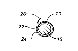
In FIG. 2, outer electrode 20 is shown disposed such that the terminal ends 26 o'f hooks
22 are constrained between outer electrode 20 and inner electrode 16.
In FIG. 3, outer electrode 20 has been rotated relative to inner electrode 16 via relative
rotation of sheath 18 and conductor/insulator 12, 14, until terminal ends 26 of hooks 22 are
released and spring outwardly beyond the outer surface of outer electrode 20.
In FIGS. 4 and 5, outer electrode 20 has been rotated further relative to inner electrode 16
so as to fully expose hooks 22 such that terminal ends 26 of hooks 22 are no longer disposed
within the confines of window 24 but extend outwardly through window 24 and overlie the outer
surface of outer electrode 20, albeit spaced therefrom.
In use, the lead 10 of the present invention is introduced transvenously in conventional
fashion into the ventricle of the heart with the hooks 22 fully sh~q~fh~d by outer electrode 20 to
2 0 prevent injury to the patient as the lead is passed through blood vessels, heart charnbers and
valves. Once positioned properly in the ventricle, relative rotation between electrodes 16 and 20
is effected as described above to expose hooks 22, and inner electrode 16 and outer electrode 20
are then rotated in unison to engage the terrninal ends 26 of hooks 22 into cardiac tissue,
preferably the septum. Such action fixes the electrode in place and, because the hooks 22 are
electrically connected to electrode 16 and spaced apart equally to create more edge effects and to
distribute the electrical energy uniformly through the septurn, it is believed to result in a lower
defibrillation threshold than would otherwise be obtained.

Representative Drawing
A single figure which represents the drawing illustrating the invention.
Administrative Status

For a clearer understanding of the status of the application/patent presented on this page, the site Disclaimer , as well as the definitions for Patent , Administrative Status , Maintenance Fee  and Payment History  should be consulted.

Administrative Status

Title Date
Forecasted Issue Date Unavailable
(86) PCT Filing Date 1996-05-31
(87) PCT Publication Date 1996-12-19
(85) National Entry 1997-10-24
Examination Requested 1997-10-24
Dead Application 2002-01-28

Abandonment History

Abandonment Date Reason Reinstatement Date
2001-01-29 FAILURE TO PAY FINAL FEE
2001-05-31 FAILURE TO PAY APPLICATION MAINTENANCE FEE

Payment History

Fee Type Anniversary Year Due Date Amount Paid Paid Date
Request for Examination $400.00 1997-10-24
Application Fee $300.00 1997-10-24
Maintenance Fee - Application - New Act 2 1998-06-01 $100.00 1997-10-24
Registration of a document - section 124 $100.00 1998-07-14
Maintenance Fee - Application - New Act 3 1999-05-31 $100.00 1999-05-13
Maintenance Fee - Application - New Act 4 2000-05-31 $100.00 2000-05-15
Owners on Record

Note: Records showing the ownership history in alphabetical order.

Current Owners on Record
SULZER INTERMEDICS INC.
Past Owners on Record
LIN, JACK HONG-ZEN
Past Owners that do not appear in the "Owners on Record" listing will appear in other documentation within the application.
Documents

To view selected files, please enter reCAPTCHA code :


To view images, click a link in the Document Description column. To download the documents, select one or more checkboxes in the first column and then click the "Download Selected in PDF format (Zip Archive)" or the "Download Selected as Single PDF" button.

List of published and non-published patent-specific documents on the CPD .

If you have any difficulty accessing content, you can call the Client Service Centre at 1-866-997-1936 or send them an e-mail at CIPO Client Service Centre.


Document
Description 
Date
(yyyy-mm-dd) 
Number of pages   Size of Image (KB) 
Abstract 1997-10-24 1 52
Description 1997-10-24 3 164
Claims 1997-10-24 1 45
Drawings 1997-10-24 1 20
Representative Drawing 1998-02-11 1 3
Cover Page 1998-02-11 2 74
Description 1997-10-25 4 180
Claims 1997-10-25 1 46
Assignment 1998-07-14 4 121
Assignment 1997-10-24 7 230
PCT 1997-10-24 13 525
Prosecution-Amendment 1997-10-24 6 278
Correspondence 1998-01-27 1 27
PCT 1997-10-25 1 73