Note: Descriptions are shown in the official language in which they were submitted.
CA 02219357 2000-09-15
METHODS AND APP,~RATUS FOR INCREASING ACCEPTANCE AND
ADJUSTING THE FATE OF PRESSURE VARIATIONS WITHIN A
PRESPECIFIEI~ RANGE IN PRECHARGED FLUID STORAGE SYSTEMS
BACKGROUND OF THE INVENTION
1. Field of the Invention
The _invention generally relates to fluid storage
systems such as, for example, systems used for storing
drinking water (including both reverse osmosis ("RO") and
well storage systems), hydronic systems which store hot
water for heating purposes, chilled water storage systems,
water treatmeni~ systems, and the like.
More particularly, the invention relates to
expansion and storage tanks (hereinafter collectively
referred to as expansion tanks), typically used in the
aforementioned exemplary systems to store fluid under
pressure; and specifically to methods and apparatus for
(a) increasing expansion tank "acceptance" (defined herein
as working fluid storage capacity); and (b) adjusting the
rate of pressure variations within a prespecified range in
precharged flu_Ld storage systems (for example, holding
pressure down below a prespecified threshold value for a
1
CA 02219357 2000-09-15
given volume of acceptance, stored water temperature level,
etc.).
The term "working fluid" is defined herein as the
product fluid, e.g., the drinking water itself in an RO
system, the hot water in a hot water heating system, etc.;
as opposed to an "expansion fluid" which is a fluid that
expands and contracts and exists only in an expansion tank
(i.e., is not intended for delivery to a customer or to mix
with the working fluid), such as a fluid used to precharge
the expansion tank.
2. Description of the Related Art
Expansion tanks used in fluid storage systems are
well known by 'those skilled in the art. Typically,
expansion tan ks are divided into two sections (or portions):
one that may b~~ precharged with a fluid under pressure, for
example, a gas such as air from a first fluid source; and
the other being connected to a second fluid source, for
example, the hot water source in a hot water heating system.
Examples of expansion tanks may be seen in U.S.
Patent No. 3,524,475; U.S. Patent No. 5,:386,925, assigned to
the same assignee as the instant invention; and Canadian
Patent Application Serial No. 2,175,537, filed May 1, 1996,
assigned to th~=_ same assignee as the instant invention.
2
CA 02219357 2000-09-15
The tanks described in the above-mentioned
application and patents all use a deformable diaphragm to
divide the tank into the aforementioned two sections. The
pressure in the precharged section varies with temperature
and as the diaphragm. is displaced to accommodate variations
in the volume (or temperature) of a fluid (e. g., water)
being stored in the other section.
When, for example, the expansion tank is
incorporated in a hot water heating system (having a fixed
mass of hot water within the system), the variation in
volume is caused when the boiler water is heated and cooled
in the normal ~ycli.c operation of the heating system.
If t:he expansion tank is a part of a water storage
system, the variation in volume occurs as tap water is drawn
and when the pump operates to replace the water drawn from
the tank. The diaphragms called for in the exemplary
aforementioned prior art separate the expansion fluid stored
in one section of the tank, from the working fluid stored in
the other section of the tank.
3
CA 02219357 1997-10-24
'' '
One of the drawbacks of current expansion tank
design is the limitation of acceptance volume as a result vf.
pressure build-up as fluid expands into the tank. This
would not be a problem if the pressure was allowed to
increase to any level. Practical considerations, however, '..
such as pressure relief devices and system component
integrity, limit the maximum acceptance volume.
For example, an expansion tank having an initial
charge of 5 psig and a maximum pressure limit, due to a,
relief valve of 3o psig, will have an acceptance of about 5~
percent. Thus about half the tank volume is wasted, .
requiring an oversized, more expensive tank than
theoretically necessary.
In one special case involving reverse osmosis (RO}
systems, the build-up of pressure in the tank reduces the
efficiency of upstream water purification processes. As
those skilled in the art will readily appreciate, the amount,
of water purified by, for example, an upstream membrane, is
a strong function of the pressure drop across the membrane.
A good recovery rate (for the purification process} for a
residential system would be 25 percent. Since'the process
is slow and typical recoveries arefone gallon per hour, a
storage system is needed.
4
CA 02219357 1997-10-24
one of the best systems available for the RO
application is the diaphragm expansion tank (such as tho::e
described in the incorpor<~ted references). The drawback is
that at 5 psig the recovery rate may be 25% at a supply
pressure of 60 psig; however, by the end of the storage
Cycle the tank pressure may be 40 psig with the recovery
rate falling to approximai~ely S percent (a poor recovery
rate .
Attempts to solve this problem typically focus on
the use of electric and hydraulic pumps and valves to allow
storage at low pressure.
In view of the prior art it would be desirable to
provide methods and apparatus for use in fluid storage
systems that do not require the use of additional equipment,
such as the aforementioned pumps and valves, to solve thes
pressure, acceptance and recovery rate problems explainect
hereinabove with referencE: to the exemplary RO fluid storage
system.
More particular7Ly, it would be desirable to
provide to an expansion tank Within which~the internal tank
pressure, after being charged at some predetermined minimum
required pressure, can be maintained within a predefined
acceptable pressure range (as the tank goes from minimum to
maximum acceptances which enables a greater percentage of
CA 02219357 1997-10-24
, . ,
the entire tank volume to be used fox storage than in
conventional fluid storage systems.
More generally, it would be desirable to provide
methods and apparatus for increasing the working fluid
storage capacity of prech;arged fluid storage systems: anc!
for holding down pressure increases in precharged fluid
storage systems for a given volume of acceptance.
In line with the aforestated desires, it would be
desirable-to grovide methods and apparatus for realizing a
"vapor spring"for use in a fluid storage system, where l:he
vapor spring utilizes somi_thing other than an ideal gas t~s
an expansion fluid (ideal gases being typically used in
conventional fluid storage systems) to: (a) increase the
amount of working fluid that can be stored in a fluid
containment vessel at a given pressure at ambient system
operating temperature when compared with the amount of
working fluid that could he accepted in such a vessel if an
ideal gas expansion fluid had been used to pre-charge they
vessel; and (b) reduce pressure increases in a fluid
containment vessel for a given volume of acceptance at
ambient system operating i~emperature when compared with t:he
use of an ideal gas expan:aion fluid in the vessel for the:
given volume of acceptance:.
6
CA 02219357 1997-10-24
. . , , .
Further yet, it would be desirable to provide
processes for adjusting the rate of pressure change, within
a fluid containment vesse7l, within a prespecified pressure
range at ambient temperature, as the volume of working f7.uid
stored in the vessel changes; and for adjusting the rate of
pressure change, within a fluid containment vessel, withj.n a
prespecified pressure range at ambient temperature, as the
temperature of working florid stored in the vessel changes.
ST1MMARY OF THE INVENTION
Accordingly, it is a general object of the
invention to provide improved expansion tanks for use in hot
water heating systems, pressurized water systems, and thE:
like.
It is a further geiseral object of the invention to
provide methods and apparatus for use in fluid storage
systems that do not requi~.~e the use of additional equipme~_nt,
such as the aforementioned pumps and valves, to solve the:
pressure, acceptance and recovery rate problems.
Further yet, it is a general object of the
invention to provide methods and apparatus for increasing
the working fluid storage capacity of precharged fluid
storage systems: and for holding down pressure increases in
7
CA 02219357 1997-10-24
4
precharged fluid storage systems for a given volume of
acceptance.
More particular:Ly, it is an object of the
invention to provide to an expansion tank within which ttae
internal tank pressure, after being charged at some
predetermined minimum required pressure, can be maintained
within a predefined accepitable pressure range {as the tank
goes from minimum to maximum acceptance) which enables a
greater percentage of the entire tank volume to be used i:or
storage than in conventional fluid storage systems.
Furthermore, it is a specific object of the
invention to provide methods and apparatus for realizing the
aforementioned "vapor sprang" utilizing something other than
an ideal gas as an expans:Lon fluid to: (a) increase the
amount of working fluid that can be stored in a fluid
containment vessel at a given pressure at ambient system
operating temperature when compared with the amount of
working fluid that could be accepted in such a vessel if an
ideal gas expansion fluid had been used to pre-charge the:
vessel; and {b) reduce pre=ssure increases in a fluid
containment vessel for a given volume of acceptance at
ambient system operating i:emperature when compared with the
use of an ideal gas expan::ion fluid. in the vessel far the:
given volume of acceptance:.
8
-__ .... _ _ . _..__. . _ . .. __ .. .. ._.. .. __... _._ -_._.. . ._ _.._ ..
. . _ _ . .
CA 02219357 1997-10-24
' . _ ,
< ..
Still further, it is an object of the invention to
provide (a) a process for adjusting the rate of pressure
change, within a fluid containment vessel, within.a
prespecifi.ed pressure ran~~e at ambient temperature, as the
volume of working fluid stored in the vessel changes: an<3
(b) a process for adjusting the rate of pressure change,
within a fluid containment vessel, within a prespecified
pressure range at ambient temperature, as the temperature of
working fluid stored in the vessel changes.
According to the invention, a "volatile" fluid
(defined herein as a fluid having a boiling point within the
predetermined pressure and temperature operating ranges :Eor
a given system), is used .at least in part as the expansion
fluid in an expansion tank included in a fluid storage
system; as opposed to the utilization of a pure ideal ga;s
expansion fluid, such as air (where an ideal gas is any
substance that has the equation of state pressure times
specific volume equalling temperature times a constant), as
is used in conventional expansion tanks.
The volatile florid, whether pure or combined w:lth
an ideal gas to temper the expansion fluids sensitivity i:o
temperature, can be'used to realize a relatively constani~
pressure "vapor spring" to make internal expansion tank
pressure relatively independent of acceptance (where the
term "relatively" in each instance is referring to a
9
CA 02219357 1997-10-24
. . . , ,
comparison between the use of an expansion fluid that
contains a volatile liquid and one that does not contain
such fluid); and realize the objectives stated hereinbefore.
fore particularly, the invention is directed,
according to a first aspect of thereof, to a method for
increasing the working fluid storage capacity of a
precharged fluid storage system, wherein the system includes
a fluid containment vessel, flexible means for separating
the interior of the vessel into (a) a first portion for
storing an expansion fluid used to precharge the vessel at
ambient temperature to a predetermined back pressure exerted
on the means for, separating and into (b) a second portion
for storing the working fluid, comprising the steps of:
(a) precharging the vessel by introducing a volatile
expansion fluid into the first portion of the vessel; an~3
(b) introducing the working fluid into the second portion of
the vessel to displace the means for separating and cause
the volatile expansion fluid to at least in part condense to
reduce the increase of the back pressure of the volatile
expansion fluid on the means for separating in comparison
with the back pressure that would be exerted on the mean:
for separating using an ideal gas expansion fluid, to
thereby permit additional working fluid to be introduced
into the vessel.
CA 02219357 1997-10-24
< <
A further aspect of the invention is directed to a
method for holding down pressure increases in a precharged
fluid storage system for a given volume of acceptance,
wherein the system includes a fluid containment vessel,
flexible means for separating the interior of the vessel
into (a) a first portion for storing an expansion fluid 'used
to precharqe the vessel at ambient temperature to a
predetermined back pressure exerted on the means for
separating and into (b) a second portion for storing the
working flwid, comprising the steps of: (a) precharging 'the
vessel by introducing a volatile expansion fluid into the
first portion of the vesselF and (b) introducing the wor:King
fluid into the second portion of the vessel to dis~rlace 'the
flexible means for separating and cause the volatile
expansion fluid to at leaat in part condense and exert a
back pressure on the meana for separating which is less i~han
the back pressure that would be exerted on the means for
'separating by an ideal ga:a expansion fluid for the volume of
working fluid accepted, to thereby hold down pressure
increases in the vessel for a given volume of acceptance"
According to aliternate embodiments of these first
two aspects of the invention, the foregoing methods may
further comprise the step of combining the volatile
expansion fluid with a predetermined amount of an ideal c~as
f _
(such as air) to modulate the boiling point of the expan=oion
fluid. This would enable a desired back pressure to be
11
_ __~_.._._ . . _~_._ .. -. -_. .. ._. .. .__.._ . . . ;
CA 02219357 1997-10-24
r ,
Y ~ a
achieved if, for example, the vapor pressure, of the vol.atilc~
fluid does not equal the desired back pressure or if is
desired to,have the hack pressure increase slightly with
acceptance, etc.
' Additional alternate embodiments of the invention,
which may be used depending on the application of the
invention, contemplate using a refrigerant as the
aforementioned volatile expansion fluid; utilizing a
non°toxic volatile expansion fluid; and/or using a
nonflammable volatile e:Kpansion fluid.
Another aspect of the invention is directed t~~
apparatus. for increasing the working fluid storage capacity
of a precharged fluid storage system, comprising: (a) a
fluid containment vessel;; (b) flexible means for separating
the interior of the vesss:l into (1) a first portion for
storing an expansion flui'_d used to precharge the vessel at
ambient temperature to a predetermined back pressure exerted
on the means for separat~.ng and into (2) a second portion
for storing the working fluid; (c) a volatile expansion
fluid located in the first portion of the vessel: and
(d) a working fluid located in the second portion of the
vessel which displaces th.e means for separating to cause the
volatile expansion fluid to at least in part condense and
act as a pressure spring to reduce the increase of the back
pressure of the volatile expansion fluid on the means for
12
CA 02219357 1997-10-24
__... ._.__,_. ....._. ._.__.__ . _,
_.. ,.. ...
r
i
. separating in comparison faith the back pressure that would
be exerted on the means for separating using an ideal gas.
expansion fluid, to thereby permit additional working florid
to be introduced into the vessel.
A still further aspect of the invention is
directed to apparatus far holding down pressure increases in
a precharged fluid storage: system for a given volume of
acceptance, comprising: (~;) a fluid containment vessel;
(b) flexible means for separating the interior of the vessel
into (1) a first portion for storing an expansion fluid used
to precharge the vessel at. ambient temperature to a
predetermined back pressure exerted on the means for
separating and into (2) a second portion for storing the
working fluid; (c) a volatile expansion fluid located in the
first portion of the vessel: and (d) a working fluid located
in the second portion of the vessel which displaces the
means for separating to cause the volatile expansion flui~3
to at least in part condense and act as a pressure spring to
exert a back pressure on the means for separating which i;s
less than the back pressure that would be exerted by an
ideal gas expansion fluid for the volume of working fluid
accepted, to thereby hold down pressure increases in the
vessel ror a given volume mf acceptance.
13
CA 02219357 1997-10-24
Further alternate embodiments of the invention
(from the apparatus perspective), which may be used
depending on the application of the invention, contemplate
the expansion fluid being a combination of a volatile florid
and a predetermined amount of an ideal.gas (such as air) to
modulate the boiling point of the fluid combination; the
expansion fluid being (at least in part) a refrigerants i:he
volatile expansion fluid laeing non-toxic volatile and/or
non-flammable.
Those skilled in the art will readily appreciai:e
that the invention may be practiced and used in a wide
variety of fluid storage ;systems including, without
limitation, "inventory storage" systems, examples of~whic:h
include reverse osmosis s;lstems and well water storage
systems: and in "cushioned storage" system, such as hydronic
storage systems and chilled water storage system.
The invention may be further characterized as a~
precharged fluid storage :>ystem, comprising: (a) a fluid
containment vessel for separately storing_both a working
fluid and an expansion fluid within the vessel; and (b) a~
pressure vapor spring that: utilizes a volatile expansion
fluid to permit additional. working fluid to~be introducedv
into the vessel at a given pressure, when compared with th.e
amount~of working fluid that could be accepted using an
ideal gas expansion fluid at the given pressure; while still
14
CA 02219357 1997-10-24
Y
another aspect of the invention may be characterized as a
precharged fluid storage system, comprising: (a) a fluid
containment vessel for separately storing. both a working
fluid and an expansion fluid within the vessel; and,(b) a
pressure vapor spring that utilizes a volatile expansion
fluid to reduce pressure increases within the vessel for a
given volume of acceptance when compared with the use of an
ideal gas expansion fluid in the vessel for the given volume
of acceptance.
The invention may also be characterized as a
process for adjusting the rate of pressure change, within a
fluid containment vessel, within a prespecified pressure
range at ambient temperature, as the volume of working fluid
stored in the vessel changes, comprising the steps of:
(a) separating the interior of the vessel into two portions
utilizing a flexible means for separating; (b) prechargi~ng
the fluid containment vessel by introducing at least some=
volatile expansion fluid into one of the interior portions
of the vessel; and (e) introducing a working fluid into i~he
other interior portion of the vessel to displace the means
for separating and cause the volatile expansion fluid to at
least in part condense to reduce the increase of the back
pressure of the volatile expansion fluid on the means fow
separating as the volume of working fluid increases.
CA 02219357 1997-10-24
Alternate embodiments of the aforestated processes
may further comprise the steps of removing working fluid
from the other interior portion of the vessel to relax
displacement of the means for separating and cause the
volatile expansion fluid to at least in part boils combin,~ng
the volatile expansion fluid with a predetermined amount i~f
an ideal gas to modulate tlhe boiling point of the expansion
fluido using a volatile fluid that is (at least in part) ~~
refrigerant, non-toxic and,ior non-flammable. .
Finally, the inveantivn also be characterized as a
process for adjusting the hate of pressure change, within a.
fluid containment vessel, within a prespecified pressure
range at ambient temperature, as the temperature of working
fluid stored in the vessel changes, comprising the steps af:
(a) separating the interior of the vessel into two portions
utilizing a flexible means for separating; (h) precharging
the fluid containment vessel by introducing at least some
volatile expansion fluid into one of the interior portions
of the vessel: and (c) introducing a working fluid into the
other interior portion of the vessel to displace the means . .
for separating and cause the volatile expansion fluid to at
least in part condense to reduce the increase of the back
pressure of the volatile expansion fluid on the means for
separating as the temperature of the working fluid
introduced increases.
16
CA 02219357 1997-10-24
I . , . , . , ,.
This last chara~eterization of the invention (i.e.,
a process for adjusting the rate of pressure change, within
a fluid containment vessel, etc.) may also include the step
of lowering the temperature of the working fluid to relax
displacement of the means for separating and cause the
volatile expansion fluid to at least in part boil.
The invention, ;as exemplified by the various
aspects and characterizations thereof described hereinabove,
features the ability to increase expansion tank acceptance
while maintaining interna7t tank pressure.within limits tY~at
will not affect tank integrity, will not trigger pressure
relief mechanisms, etc.
Furthermore the invention solves the
aforementioned recovery rate problem in Ro systems without
having to resort to the use of electric or hydraulic pumps
and/or valves to facilitate fluid storage at low pressure.
These and other objects, embodiments and featur~as
of the present invention and the manner of obtaining them
will become apparent to those skilled in the art, and the
invention itself will be best understood by reference to
the following Detailed Description read in conjunction with
the accompanying Drawing.
17
CA 02219357 1997-10-24
' . ' ~ .
BRIEF DESCRfPTION OF TFiE DRAWING
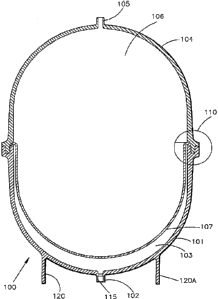
FIG. 1 is a vertical cross-section view of an
exemplary expansion tank within which the teachings of the
inventiomnay be practiced.
FIG. 2 is a vertical cross-section view of the
tank depicted in FIG. 1 after being pre-charged, including
means for separating shown deformed by the expansion fluid
! used to pre-charge the tank.
FIG. 3 is a graph depicting pressure versus fluid
temperature when using a commercially available refrigerant
(R11) as an expansion fluid in an illustrative embodiment. of
the invention.
FIG. 4 is a graph that compares a pure air charge
versus a charge of using am expansion fluid that~combines
air and R11.
FIG. 5 is a tab3.e that lists three exemplary
applications in which the instant invention may be
beneficially put to use.
18
CA 02219357 1997-10-24
a ,
. .
. L . . , , a ,
FIG. 6 which is graph depicting the saturation
curves for four exemplary volatile expansion fluids(R-245f<i,
R-236ea, R-236 fa and R-21), all have boiling points in th~_
40-100 degree F range.
FIG. 7 is a graph which depicts the relationship
between temperature, tank pressure, and acceptance for
samples of R-245fa,~air and R-245fa combined with air,
showing what happens to tank pressure as the temperature
varies from 50 to 100 degrees F at zero percent acceptance.
FTG. 8 is a graph which depicts the relationship
between temperature, tank pressure, and acceptance for
samples of R-245fa, air and R-245fa combined with air,
showing what happens to tank pressure as the temperature
varies from 50 to 100 degrees F at seventy five percent
acceptance.
FIG. 9 is a graph illustrating the effect the
quantity of air and 245fa tr,ave on an exemplary RO system.
In FIG. 9 the quantity of 245fa is kept constant at .175
pounds; while the quantity of air varies from .005 to .010
pounds. There are two sets. of curves in FIG. 9, one set
corresponding to zero percent acceptance and the other to 90
percent acceptance.
19
CA 02219357 2000-09-15
FIG. 10 is also a graph illustrating the effect
the quantity of air and 245fa have on an exemplary RO
system; however in FIG. 10 the quantity of air is kept
constant at .007 pounds; while the quantity of 245fa varies
from .15 to .225 pounds. There are two sets of curves in
FIG. 10, one s~~t corresponding to zero percent acceptance
and the other to 90 percent acceptance.
FIG. 11 is a graph which plots temperature versus
pressure at various levels of acceptance in a fluid storage
system using an expansion fluid consisting of .175 pounds of
245fa combined with .007 pounds of air.
DETAILED DESCRIPTION
Reference ahould now be made to FIG. 1 which is
presented for background purposes and shows a vertical
cross-section view o:E an exemplary expansion tank within
which the teachings o.f the invention may be practiced.
Tank 100 is the subject of the invention in
copending Canadian Patent Application Serial No. 2,175,537,
filed May 1, 1996, assigned to the same assignee as the
instant invention; and is only intended to define one
environment (an inventory system type expansion tank which
could, for example, be used in a reverse osmosis storage
system), of the many environments in which the benefits of
CA 02219357 2000-09-15
the instant invention may be realized.
Illustrative expansion tank 100 is shown in FIG. 1
to include a first molded plastic tank section 101,
integrally including first connection means 102, for
enabling fluid from a first fluid source (not shown) to be
placed in flui~~ communication with a first interior portion
103 of expansion tank 100; and (b) a second molded plastic
tank section 104, which when joined together with first
molded plastic tank section 101 forms the expansion tank
fluid containment vessel 100, integrally including second
connection means 105 for enabling fluid from a second fluid
source (not shown) to be placed in fluid communication with
a second separate interior portion 106 of expansion tank
100.
First. connc=_ction means 102 and second connection
means 105 provide passageways through which fluid from the
first and second fluid sources respectively, may be
introduced into and rnay be withdrawn from expansion tank
100.
According i.o one embodiment of the invention
described in Canadian Patent Application Serial
No. 2,175,537, first connection means 102 and second
connection means 105 are threaded (as shown for example at
115 in FIG. 1) to permit easy installation of valves (not
21
CA 02219357 2000-09-15
shown) into the depicted passageways. Exemplary tank 100
shown in FIG. 1 also includes tank stand member 120 (and
corresponding .~orti.on 120a of that member in the depicted
vertical cross-section view), which is preferably integrally
formed as part of tank section 101 to serve as a base upon
which the tank may be rested in an upright position.
Tank 100 is also depicted as including a means for
separating (shown as 107 in FIG. 1) the tank into the
aforementioned first and second interior portions (103 and
106 respective:Ly); where means for separating 107 spans the
interior of tank 100 and is made of a flexible material.
In p=ractice, means for separating 107 can be
realized by, for example, a flexible diaphragm (single of
multiple layer;, bladder or some other application specific
membrane that separates the expansion tank into two
chambers.
Stil_L further with reference to FIG. 1, according
to a preferred embodiment of the invention described in
Canadian Patent. Application Serial No. 2,175,537, tank 100
includes means for securing (shown as 110 in FIG. 1) the
means for separating 107 (within tank 100) via a joint
formed between first molded plastic tank section 101 and
second molded plasti~~ tank section 104.
22
CA 02219357 1997-10-24
A ~
t n
For the applications contemplated by the instant
invention it is desirable that the separate fluid chambers
be formed using a material that is not permeable to eithez
of the fluids being introduced into the tank and which
allows one of the chambers to be precharged with an
expansion fluid to exert a predetermined hack pressure on
means for separating 107.
A vertical cross-section view of the tank depicted
in FIG_ 1 after being pre-charged is shown in FIG. 2,
where means for separating 107 in tank 125 is shown deformed
by expansion fluid 126 used to pre-charge the tank.
Having described an exemplary expansion tank in
which the instant inventio~a may be practiced, it should bE:
recalled fiom the Summary ~of the Invention as set forth
hereinbefore that according to the invention, a "volatile"
fluid is used at least in ;part as the expansion fluid in yin
expansion tank included in a fluid storage system (such ass
the exemplary tank shown and described with reference to
FIG. i): as opposed to the utilization of a pure ideal gar
expansion fluid, such as air as is used in conventional
exparesion tanks.
23
CA 02219357 1997-10-24
A n ,
a o
The volatile fluid, whether pure or combined w.fth
an ideal gas to temper the expansion fluids sensitivity to
temperature, can be used to realize the pressure "vapor
spring" contemplated by the invention.
This will be demonstrated hereinafter with
reference to FIG. 3 and FIG. 4; first, however, the
principles of the invention should be understood and can be
explained with reference to the following example.
Initially, assume that an expansion tank in a
fluid storage.system is pre-charged with a small amount of
fluid. This could be accomplished, again for example, by
introducing the pre-charge fluid into an expansion tank like
tank 100 via connection 102 (shown in FIG. 1}; and than
sealing that portion of the tank by closing a valve.
Assume further that the fluid vapor pressure in
tank section 103 in FIG. 1 is 5 psig at 70 degrees F~. Thus
if the tank is at 70 degrees F the vapor space-would
stabilize at 5 psig.
As a fluid expands into the tank (for example in
the RO case, if water expands into tank 100 via connection
105} and displaces the ms~mbrane (means for separating 107),
enough vapor would condense to maintain a system pressure at
psig. The opposite woLtld occur if water left the tank.
24
CA 02219357 1997-10-24
As the vapor volume increases, enough liquid would evaporate
to maintain the vapor at 5 psig. During extremely rapid
volume changes, there may be some lag in the process.
As long as the temperature remains constant and
there is liquid and vapor present, the equilibrium pressure
will not change. Factors that can change the pressure are
the temperature, the amount of fluid in the charge, and the
presence of non-condensing gases therein.
Reference should now be made to FIG. 3 which is ~~
graph depicting~pressure versus fluid temperature when using
a commercially available refrigerant R11 (used only as a
vehicle for illustrating the principles of the invention) as
the fluid charge (i.e., as the expansion fluid) for values
of acceptance from 0-90 percent.
The assumptions made are that the tank and fluid
temperatures are the same and the total tank volume is 1
cubic foot X7.5 gallons). The refrigerant side of the means
for separating in the expansion tank was filled with .38
pounds of fguid. This amount resulted in a back pressure c~f
5 psig at 70 degrees F on't:he means for separating, the
minimum needed to operate a faucet in an RO system.
25
CA 02219357 1997-10-24
. . 1
At 70 degrees F the tank pressure varies from :5 to
8.5 prig as the acceptance varies from 0-90 percent. Even
at 90 degrees F the pressure only varies from 6-18 psig
through the same range of acceptance. By comparison, if the
tank were precharged with air as the expansion fluid, the
pressure would vary from 6 to over 190 psig at 90 degrees F
over the same range of acceptance. At 120 degrees F,
pressures remain below 3o psig at acceptances of 5o percent
and below. This plot show's dramatically the potential of the
invention. An RO system can operate at a wide range of
ambient conditions (for example, 70-90 degrees F) and nevef
exceed half the current typical Ro system maximum tank
pressure to help avoid th:e serious adverse affects vn -
upstream purification processes and recovery rates as
experienced using prior a:rt fluid storage systems that use
an ideal gas as an expan~:ion fluid.
Another approach contemplated by the invention., in
a preferred embodiment thereof, is that of using an
expansion fluid that is a combination of a saturated fluid .
and a non-condensing gas,. such as air, to precharge the
expansion tank. By using a non-condensing gas together with -
a saturated fluid, the performance of the fluid storage
system can be tailored to perform between a system that uses
a pure saturated fluid and one that uses, a pure ideal g!as,
such as air.
26
CA 02219357 1997-10-24
, , g . .
xhose skilled in the art will readily appreciat~a
that FIG. 3 also illustrates that by limiting the amount a~f
volatile fluid, at low acceptance/high temperature all of
the volatile fluid will be in vapor form and thus the
pressure will be less sensitive to temperatures. Thus, with
.38 lbs. of R11, at zero acceptance, all of the fluid is fn
the vapor state at temperatures above 62 degrees F. At 25~
acceptance at temperatures above 78 degrees F the fluid i.s
in a vapor state (all the liquid has evaporated).
A better understanding of how such a system would
perform may be seen with reference to FIG. 4. FIG. 4
comgares a pure air charge versus a charge of using an '
expansion fluid that combines air and R11. Comparing the
two cases at 70 degrees F, at zero percent acceptance, both
systems are at 5 psig. At 75 percent acceptance, however,
the air/R11 system is at 25 psig while the pure air system
is at 65 psig. Even at higher temperature, the air/R11
system is only 35 psig while the pure air system is, at 68
psig.
Clearly FIG. 4 dlemonstrates that the performance
of the fluid storage system can be tailored by using a
non-condensing gas together with a saturated fluid as the
pre-charge expansion fluidl.
27
CA 02219357 1997-10-24
A more detailed analysis of exemplary applications
served by the instant invention, operating conditions th~it
would have.to be met in the context of such applications,
and further graphs demonstrating the benefits of the
invention, are presented hereinafter with reference to
FIGS. 5-1D.
FIG. 5 is a table that lists three exemplary
applications in which the instant invention may be '
beneficially put to use. The applications are characterized
as either an "inventory" type system or a "cushioned" system'
(previously.defined herein by way of example). More
particularly, in an inventory type system, such as a RO ~~r
well system, the storage system is storing product; while in
a cushion system the storage system is accommodating them
expansion and contraction of the working fluid.
In applying the principles of the invention al~~nq~
With the methods and apparatus taught and claimed herein,
two parameters are important; the pressure and temperature
operating ranges of the fluid storage system.
Pressure is important because if more than
anything else, it enters into the selection of the expan,sian
fluid to use. In general, expansipn fluids with boiling
points near room temperature (50-1oD degrees F) are
preferred for the exemplary applications discussed herein.
28
CA 02219357 1997-10-24
gn general, a small temperature range is also desired so
that: the pressure remains relatively constant.
Iri Conventional systems using air or other ideal
gaseous fluid as an expansion fluid, pressure increases
greatly as the storage volume is compressed. On the other
hand, as the temperature changes, the pressure increase i.s
modest. If a pure two phase (liquid and gas) expansion
fluid is used, which is contemplated by one aspect of the:
present invention, the prf~ssure remains relatively constant
during volume changes (rellative to the pressure changes that
would be experienced using an ideal gas as an expansion
fluid); however the pressure can change rapidly with an
increase in temperature.
The two approaches discussed hereinabove, pure
ideal gas versus two-phase fluid have differing affects on
the volume, pressure and temperature relationships within a
given system. A further :aspect of the invention is direcaed
to a fluid storage system using a hybrid of the two.
From the table chown in FIG. 5 it appears that R/O
or well systems are ideal applications for the invention
because of their relative:Ly narrow operating temperature
ranges; however significant application can also be found in
the case of the exemplary hydronic system. Should the w:Ldth
of the temperature operating range of a given system prove
29
CA 02219357 1997-10-24
n i a ' a
problematic one could, for example, separate the fluid being
stored from the heating source to bring down the temper~~ture
range of the fluids stored down into a narrower band.
In selecting any particular expansion fluid to be
used for,the exemplary applications shown in FIG. 5 one
criteria could be to choose a fluid having a boilinq po~Lnt
well within the range of the typical temperatures
experienced. ~~Boiling p~oint~~ is defined herein to mean the
temperature at which a fluid boils at normal atmospheric:
pressure, i.e., zero psig. other criteria could include:
selecting a fluid that is safe in the context of the sysaem
in which it is used.
For example, an expansion fluid chosen for use: in
an inventory system storing drinking water would ideally be
non-toxin tv avoid contamination if the expansion fluid and
working fluid were ever i:,o come in contact with one another.
The expansion fluid being non-flammable becomes important in
certain operating environments since a flammable fluid
otherwise chosen to boil at or near room temperature would
produce a flammable vapor in the event of~a leak. other
applications might tolerate some degree of toxicity, etc.,
as determined on a case by case basis depending on the
application of the fluid storage system.
CA 02219357 1997-10-24
., s . >
Several fluids ~~hosen to further illustrate the:
principles of the invention and its advantages {and not
because the use of one is favored over the use of another
fluid whether or not discussed herein) are depicted in
FIG. 6 which is a plot of saturation curves for the
exemplary identified fluids. These fluids'{R-245fa,
R-236ea, R-236 fa and R-2:L) all have boiling points in the
40-10o degree F range. The fluids plotted are all
refrigerants; however the invention more generally
contemplates the use of a volatile fluid (as defined
hereinbefore) in whole or in part to constitute an expana,ion
fluid; whether or not the volatile fluid is a refrigerant..
For the sake of illustration only, one of these
fluids (R-245fa, sometimes referred to hereinafter simply as
°'245fa"), was evaluated taken alone, in combination with air
and in comparison with ai:- alone, to be able to illustrate
the relationship between temperature, tank pressure, and
acceptance for various samples of a pure volatile liquid
expansion fluid {like the R-245fa), a pure ideal gas
expansion fluid (like the air) and combinations of a
volatile liquid and an ideal gas.
In particular, fIG. 7 and FIG. 8 are graphs which
depict the aforementioned relationship between temperature,
tank pressure, and acceptance for samples of R-245fa, air
and R-245fa combined with air. More particularly, FIG. 7
31
CA 02219357 1997-10-24
. >
s ,
shows what happens to tank pressure as the temperature
varies from 50 to loo degrees F at zero percent acceptance.
With the pure fluid (245fa only) the pressure is
subatmospheric at 50 degrees F, about 5 gsig at room
temperature, and peaks at about 10 psig when it becomes pure
vapor at 8o degrees F. Air shows a pressure of 5 psig at 50
degrees F which increases slightly with temperature. The
mixture of air and 245fa increases the pressure at low
temperature when compare~3 to 245fa alone, making (for
example) an RO system workable down to 60 degrees F. The
dramatic change in slope at ?0 degrees F occurs because both
the 245fa and air are in the gaseous state.
FIG, 8 shows the same variables: however, for an
acceptance of 75 percent. The shaded region is the
acceptable range of operation for a typical RO system which
is used as an exemplary aystem hereinafter to explain the
remainincJ principles of 'the invention. As shown in FIG. 8,
the air only case is, well above this region. In fact, the
maximum practical accept;3nce is 60 percent for air.
If pure 245fa .is used, it can be seen that the:
acceptance can be much higher than 75 percent; however,. an
RO system would not operate much below 70 degrees F. T1~.~e
iuixture of air and 245fa shows an acceptable pressure
throughout the temperature range. In fact, its pressure:
will still be reasonable at a higher acceptance. Not as
32
CA 02219357 1997-10-24
~ r
~ i ~ . . ,
obvious is the fact that an RO system will. be more efficient
during the recovery part of the cycle because the pressure
i
on the downstream side of the purification membrane will be
lower. For the sake of completeness it should be noted that
FIG. 7 and FIG. 8 were prepared assuming .175 pounds of
245fa and .007 pounds of air. These assumptions Were made
to allow the exemplary RO system to operate below 70 degrees
' F.
The effect the c;uantity of air and 245fa have an
the exemplary RO system i:> illustrated in FIG. 9 and
FIG. 10, respectively_ In FIG. 9 the quantity of 245fa was
kept constant at .175 pounds; while the quantity of air was
varied from .005 to .010 pounds. There are two sets of
curves in each of FIG. 9 wind FIG. 10; One set corresponding
to zero percent acceptance. and the other to to percent
acceptance. With reference again to FIG. 9, it is apparent
from the upper set of curves (90 percent acceptance), the
less the amount of air used the better. From the lower set
of curves (zero percent acceptance) it can be seen that the
function of the air is to simply raise the initial pressure
to a useful level. By analyzing the figures described
hereinbefore it becomes apparent that, although somewhat
arbitrary, .007 pounds of air seems reasonable to use in the
exemplary RO system for which fluid constituent choices are
being made in the instant example.
33
CA 02219357 1997-10-24
The effect of the quantity of 245fa can be seen in
FIG_ 10. In FIG. 10 the c;uantity of air was kept constant
at .007 pounds; while the quantity of 245fa was varied from
.15 to .225. pounds. Surprisingly, there is little effect:
from fluid quantity on the system. At high acceptance trtere
is virtually no effect since the fluid is~saturated. A l.ow
acceptance the quantity oi: fluid determines at what
temperature the fluid reaches the all vapor state. At .7.5
pounds, the vapor state is reached at 60 degrees F: while; at
.225 pounds it occurs at ~t0 degrees F. For the exemplarh RO
system application, .175 pounds of~245fa seems reasonable: to
use since it keeps the prey sure between 5 and 10 psig in the
range of interest.
Reference shoulc! now be made to FIG. 11 which
shows a fluid storage system with .175 pounds of 245fa arid
.007 pounds of air plotted as temperature versus pressurs:_
- As can be seen from FIG.11, this system would work well for
an Ro system with a minimum pressure of 5 psig at about E.0
degrees F and a maximum pressure of 40 psig at 95 degree, F
and an acceptance of 85%, thereby demonstrating the
principles of the invention.
what has been described in detail hereinabove a.re
methods, apparatus and fabrication techniques which meat all
of the aforestated objectives. As previously indicated,
those skilled in the art Hrill recognize that the foregoing
34
CA 02219357 1997-10-24
~ ,
description has been pYes~ented for the sake of illustration
and description only. It is not intended tv be exhausti~~e
or to limit the invention to the precise form disclosed, and
obviously many modifications and variations are possible in
light of the above teaching.
The embodiments and examples 'set forth herein ~rere
presented in order to best explain the principles of the
instant invention and its practical application to therek>y
enable others skilled in 'the art to best utilize the instant
invention in various embodiments and with various
modifications as are suited to the particular use
contemplated.
In view of the above it is, therefore, to be
understood that the claims appended hereto are intended t:o
cover all such modifications and variations which fall
within the true scope and spirit of the invention.