Note: Descriptions are shown in the official language in which they were submitted.
-..
CA 02219416 2002-02-12
' CA 02219416 199?-10-27
WO 96/3443 PCTlOS96/OS132
STRUCTURE FORMING METHOD-AND APPARATUS
~ 5
This invention relates to a novel continuous structure
farming method and apparatus and to a new continuous structure
produced thereby.
The present invention provides a novel method, apparatus and
structure Which overcome the shortcomings of previous expedients.
In addition, the method, apparatus and structure provide features
and advantages not found in earlier technology.
The method and apparatus of the present invention may be
employed by individuals with only limited mechanichl skills and
experience. Structures can be produced by such individuals safely
and efficiently without supervision utilizing the method and
apparatus of the invention. The configuration and composition of
the structure can be changed easily.
The method of the invention can be modified to form a variety
of different structures with the apparatus of the invention.
Variations in physical dimensions, composition and surface
appearance, etc. can be achieved. Even with such changes, uniform
high quality can be maintained without difficulty with the method
and apparatus of the present invention.
A novel method of the present invention for forming a
continuous structure includes the steps of preselecting a liquid
reactive resin forming material, a particulate solid additive
1
a
1
CA 02219416 1997-10-27 ~ '
WO 96/34743 PCT/US96/05132
material and a porous blanket. The additive particles are mixed
with the liquid resin forming material substantially continuously
to encapsulate substantially all of the additive particles with
the resin forming material to a preselected thickness.
A pool of the resulting mixture is formed on the porous '
blanket while it is moving over an elongated arcuate surface
disposed in a preselected orientation. Part of the liquid resin '
forming material is migrated through the blanket substantially
uniformly prior to gelling of the liquid resin forming material
to form a continuous resin matrix within the structure.
A leading edge of the structure is grasped and advanced over
a generally horizontally oriented supporting surface. The leading
edge of the structure then is grasped along substantially its
entire length and advanced away from the supporting surface along
a preselected path. The structure is cut into a preselected
length and the length placed into a final configuration while the
length is flexible and adhesive.
The additive particles advantageously are mixed with the
liquid resin forming material as it is passed continuously
downwardly through an elongated mixing chamber. Preferably, the
mixture is deposited on the blanket in a reciprocating motion from
one side to the other.
The pool of the mixture advantageously is confined in contact
with the blanket between a pair of adjustably spaced elongated
arcuate surfaces with lower edges thereof positioned close
together and substantially transverse to the direction of the
advance. Preferably, the orientation of the arcuate surfaces and
the horizontal supporting surface are monitored and adjusted to
maintain the surfaces within preselected specifications.
A second blanket and/or a fibrous sheet may be included in
the structure by positioning it so the pool of the mixture is
between the two blankets. In this way, both blankets become
integral components of the structure.
If desired, pressure may be applied to the structure prior
to or after its placement in a final configuration. The pressure
advantageously is applied simultaneously across an entire width
of the structure. A preselected pattern may be formed on a
surface of the structure while pressure is applied thereto,
preferably along an extended length thereof.
2
CA 02219416 1997-10-27
WO 96/34743 PCT/US96/05132
Benefits and advantages of the novel method, apparatus and
structure of the present invention will be apparent from the
following description of the accompanying drawings in which:
Figure 1 is a view in perspective of one form of mobile
continuous structure forming apparatus of the present invention;
Figure 2 is a side view of the structure forming apparatus
of the invention shown in Figure 1;
Figure 3 is an enlarged fragmentary side view in section of
the structure forming apparatus of the invention shown in Figures
1 and 2;
Figure 4 is a further enlarged fragmentary cross sectional
view of the structure of the invention shown in Figure 1; and
Figure 5 is a schematic illustration of a structure forming
apparatus of the invention moving into position over a ditch.
As shown in the drawings, one form of novel mobile continuous
structure forming apparatus 11 of the present invention includes
a supporting portion 12, a raw material supplying portion 13, a
mixing portion 14, a matrix forming portion 15 and a control
portion 16.
The supporting portion 12 of the structure forming apparatus
of the invention includes a plurality of spaced upstanding frame
members 20, 21, 22, 23. The frame members are adjustable in
length. A plurality of generally horizontally disposed frame
sections 25, 26, 27, 28 join adjacent upper ends of the upstanding
frame members. For example as shown in the drawings, frame
section 25 extends between an upper end 30 of frame member 20 and
an upper end 31 of frame member 21.
Opposed frame sections 25, 27 are of adjustable length. This
may be accomplished as shown by dividing a frame section into two
and partially overlapping adjacent free ends within a housing 32,
33.
Spaced support sections 34, 35 extend between opposed frame
sections 25, 27 and particularly between the respective housing
32, 33 of each frame section. Mixing portion 14 and matrix
forming portion 15 extend downwardly adjustably from the support
sections between the upstanding frame members 20 - 23. Other
components (not shown) such as an operator's seat, an electrical
generator, an air compressor, a hydraulic pump and the like also
3
CA 02219416 1997-10-27
WO 96/34743 PCT/US96/05132
can be mounted on and/or suspended from the frame sections and
support sections.
Pivotable carriage means 36 extend downwardly from lower ends
37 of the upstanding frame members. Advantageously, the carriage
means include wheels 38 rotatable on axles 39. The carriages '
preferably include variable drive means 41 and include endless
track members 42. Drive means 43 advantageously adjust the length '
of frame members 20 - 23 and adjustable frame sections 25, 27.
The mobile structure forming apparatus 11 advantageously
includes four spaced upstanding frame members and four frame
sections forming a quadrangular assembly as shown in the drawings.
Preferably, the apparatus 11 includes jack means 44 extending
downwardly between the carriage means 36.
The raw material supplying portion 13 of the apparatus 11
includes a plurality of reservoirs 46 operatively connected with
the supporting portion 12. The reservoirs are connected
independently with the mixing portion 14 through flexible conduit
means 47. The raw material supplying portion advantageously also
includes a gravity feed hopper 48 adjacent the mixing portion 14
and preferably heating means 49 along the length of the flexible
conduit means.
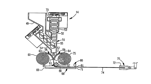
The mixing portion 14 of the structure forming apparatus 11
of the invention includes a generally vertically oriented
elongated mixing chamber 51 mounted on the supporting portion 12.
A rotatable mixing element 52 is disposed within the mixing
chamber as shown in Figure 3.
The mixing chamber 51 also preferably includes a solid
particle delivery section 54 which is disposed at an obtuse angle
to the mixing chamber. An open rotatable element 55 may be
disposed within section 54 and extend into the mixing chamber.
Advantageously, delivery section 54 is connected to the lower part
of the mixing chamber 51.
The matrix forming portion 15 of the apparatus 11 includes
mixture distributing means 56 adjacent an outlet 57 of the mixing
chamber 51. The mixture delivery means 56 includes a pair of
spaced elongated transversely disposed arcuate members 58, 59.
The arcuate members are disposed with generally horizontal lower
edges 61, 62 adjustably oriented closer together than upper edges
63, 64 thereof.
4
' CA 02219416 1997-10-27
WO 96/34743 PCT/US96/05132
First elongated structure grasping means 65 is disposed below
the lower edges 61, 62. Advantageously, as shown grasping means
65 includes a rotatable rod 66 with outwardly extending
projections or pins 67. Rod 66 is spaced from the lower edges
and aligned therewith.
Generally horizontally oriented structure support means 68
has one end 69 adjacent the rod 66. Second elongated structure
grasping means 70 is disposed adjacent an opposite end 71 of the
structure support means 68 remote from the first structure
grasping means 65. Preferably, the second grasping means 70 as
shown includes a pair of elongated hinged sections 72 aligned
with rod 66.
Advantageously, the mixture distributing means 56 includes
actuating means 73 reciprocating the outlet 57 of the mixing
chamber 51 across the width of a blanket 60 passing thereunder.
The mixture distributing means 56 preferably also includes
positioning means 77, advantageously including sensing means 78
and automatic activating means 79. Preferably, cutting means 80
with a blade 81 is included, particularly cutting means extending
parallel to and adjacent the opposite end 71 of the support means
68.
The mixture distributing means also advantageously includes
advancing means 82 for moving structure 74 along a preselected
path while the structure is flexible and adhesive. Advancing
means 82 as shown in the drawings preferably may include a
telescoping arm assembly 83 with a cable 84 to which second
grasping means 70 is attached.
If desired, pressure applying means such as a roller, belt
or opposed combinations thereof (not shown) may be included. The
roller, belt, etc. may have a patterning surface. Pressure may
be applied to the structure to conform it to an underlying
surface, to compress the structure into a more dense mass and the
like.
To form a structure employing the method and apparatus of the
invention as shown in the drawings, a liquid reactive resin
forming material is advanced from a reservoir 46 through a conduit
l
47 into mixing chamber 51. Simultaneously, other minor
ingredients e.g. colors, catalysts, etc. from another reservoir
advance through a conduit into the mixing chamber and are mixed
5
CA 02219416 1997-10-27 '
WO 96/34743 PCT/US96/OS132
with the resin forming material moving therethrough by rotatable
mixing element 52.
As the resulting liquid mixture advances down the mixing
chamber, a particulate solid additive material from hopper 48
advances through delivery section 54 into mixing chamber 51. The
additive particles mix with the liquid resin forming material
advancing therealong. '
The additive particles are mixed with the liquid resin
forming material substantially continuously, preferably in a
proportion significantly greater than that of the resin forming
material. During this mixing operation, substantially all of the
additive particles are encapsulated with the liquid resin forming
material to a preselected thickness.
The resulting mixture being delivered from outlet 57 of the
mixing chamber 51 passes downwardly between a blanket 60 and a
fibrous sheet 75 as they advance over arcuate members 58, 59.
With the lower edges 62, 62 of the arcuate members close together
in a preselected spacing, the mixture forms a pool 85 between the
converging blanket and sheet moving downwardly past the arcuate
2n member'. -Adi.T~.:tr'~geC3Ll~l~~ -the-~3lailk2t--aL3d--S~i2et-are--
advalia~e~i nt-c
rate sufficient to create movement of the additive particles
within the pool to ensure complete encapsulation and also to
maintain the particles in suspension so the mixture adhering to
the blanket and sheet is homogeneous.
As the blanket 60 and fibrous sheet 75 advance past the
closely spaced lower edges 61, 62 of the arcuate members, excess
mixture is removed and a substantially uniform preselected
thickness is retained between the blanket and the sheet.
Thereafter, part of the liquid resin forming material is allowed
to migrate through the blanket and sheet as the resulting
structure is advanced by rotating rod 66 with the pins 67
extending therefrom engaging the blanket and/or sheet.
The path of the moving structure 74 is changed as it passes
around rod 66 and onto horizontally-oriented structure support 68.
Migration of liquid resin forming material may continue during
this step and succeeding steps as the leading edge of the
structure reaches the opposite edge 71 of the structure support
and is grasped by second grasping means 70. The second grasping
means 70 shown as including a pair of hinged sections 72
6
' CA 02219416 1997-10-27
WO 96/34743 PCT/US96/05132
operatively connected to telescoping arm assembly 83 through cable
84 draws the structure 74 along a preselected path.
When a desired preselected length of the structure 74 has
reached the far edge 71 of the structure support 68, cutting means
~ 5 80 is activated causing blade 81 to move across the structure from
one side to the other. Then the cut length is carried by
telescoping arm assembly 83 to an adjacent preselected location
and positioned into a final configuration such as a ditch while
the structure is flexible and adhesive. The structure conforms
to the ditch surface and upon curing is tightly bonded thereto.
To form a preselected patterned surface on the resulting
structure, it is passed into contact with a patterning roller,
belt or a combination thereof.
To produce high quality structures of the invention, it is
important that all of the steps be carefully coordinated by
control portion 16. The control portion 16 of the structure
forming apparatus 11 of the invention includes programmable memory
means 86 and actuating means 87 responsive thereto in combination
with coordinating means 88 to control the operation of pumps,
valves and drives. Preferably, the coordinating means includes
a process controller 89 that initiates changes in the flows of
materials and speeds of drives to bring variations therein back
to the rates specified in the programs present in the memory 86.
This coordination commonly is achieved through the
transmission of information such as digital pulses from monitors
and/or sensors at the control components to the process controller
89. The operating information is compared with the preselected
programming parameters stored in the memory 86. If differences
are detected, instructions from the controller change the
operation of the components to restore the various operations to
the preselected processing specifications.
During the above steps, the sensors 78 of positioning means
77 also are sensing the orientation of the matrix forming portion
15 and particularly lower edges 61, 62 of arcuate members 58, 59
and horizonal structure support 68. If a deviation is detected
in the specifications stored in memory 86, activating means 79
automatically is energized to return the components of the matrix
forming portion to their preselected orientation.
7
CA 02219416 1997-10-27
WO 96/34743 PCT/US96/05132
As shown in Figure 4, a cross section of a typical structure
74 of the invention includes a thin continuous resin rich upper
layer 91 over a thin fibrous sheet 75 under which is a central
layer 92 including a plurality of encapsulated solid particles 93
e.g. particles from grinding discarded tires, within a continuous
resin matrix 94. The resin matrix extends throughout the
structure from the thin resin rich upper layer 91 through fibrous >
sheet 75, through particle rich central layer 92 downwardly
through blanket 60 and into a thinner resin rich lower layer 95
including a few very small solid particles 96 disposed primarily
closely adjacent to the blanket.
Advantageously, inclusion of outer upper and/or lower plastic
films (not shown) may facilitate the installation of novel
structures of the invention under adverse weather conditions or
below water or other liquids. Also, the flowing of resin through
film openings can provide adhesion of the structure to a
subsurface (not shown).
Normal maneuvering of the continuous structure forming
apparatus of the invention to maintain it centered over a ditch
ordinarily can be accomplished by increasing the speed of the
carriages 36 on one side and/or decreasing the speed of the
carriages on the other side.
Figure 5 illustrates the movement of the apparatus of the
invention to another ditch. The apparatus 11 is prepared for
movement by pivoting the carriages 36 ninety degrees from the
normal operating orientation as shown in Figure 2 using jacks 44
to raise the carriages off the ground. The apparatus then is
moved sideways up a grade and over a temporary ramp 98 until the
apparatus straddles ditch 97. Thereafter, the jacks 44 again
raise the carriages 36 so they can be pivoted back to an
orientation parallel to the ditch for resuming the ditch lining.
The same steps can be employed to move the apparatus around
obstacles such as bridges, trees, head gates, etc. To change the
width of the apparatus, the two carriages on one side can be
pivoted and driven away from or toward the center of the apparatus
and thereby lengthen or shorten the adjustable frame sections 25
and 27_ '
The liquid reactive resin forming material employed to
produce structures of the invention is selected to be capable of
8
' CA 02219416 1997-10-27
WO 96/34743 PCT/US96/05132
reaction to form the particular resin matrix desired in the final
structure. Advantageously, the resin matrix is a thermosetting
resin such as a polyurethane or polyester. Should a polyurethane
be desired, one reservoir may contain an isocyanate and another
reservoir may contain a polyol. More commonly, the reservoirs may
contain different partially formed materials which upon mixing
interact to form the desired polyurethane. Examples of such
partially formed materials include so-called "A stage" resins and
"B stage" resins.
Other resin forming systems may utilize a resin forming
material in one reservoir and a catalyst in a second reservoir.
Additional components can be premixed with one of the resin
formers, e.g. fillers, reinforcements, colors and the like.
The particulate solid additive material is mixed with the
. liquid reactive resin forming material substantially continuously,
preferably in a proportion significantly greater than that of the
resin forming material. The additive particles may be any of a
wide variety of inexpensive materials readily available at a
particular job site. Natural mineral particulate materials such
as sand and gravel normally are available or can be produced
simply by crushing rock at the site.
Also, materials such as waste or recycled materials which can
be shredded or ground into particles of suitable size can be
utilized. Particularly useful are particles formed by shredding
or grinding discarded tires. Since the particles are encapsulated
with the resin forming material and not saturated therewith, many
different waste materials may be employed.
Suitable porous blankets include woven, knit, non-woven
structures, etc. The blankets e.g. fabrics, mats, etc. may be
formed of continuous or discontinuous fibers, yarns, slit ribbons
and similar natural and synthetic fibrous materials. Reinforcing
members such as ropes, cables and the like that extend
longitudinally and/or transversely of the blanket centerline may
be included if desired.
The fibrous sheet includes products that utilize a major
proportion of short fibers oriented predominately in a single
plane. Preferably, the sheet is spot bonded at spaced points over
its surface to provide strength along its major plane and general
structural integrity.
9
CA 02219416 1997-10-27
WO 96/34743 PCTlUS96l05132
The above description and the accompanying drawings show that
the present invention provides a novel method, apparatus and
structure which overcome the shortcomings of previous expedients
and in addition, provide features and advantages not found in
earlier technology.
The structure produced with the method and apparatus of the
invention can include major proportions of recycled, waste or
other materials which are readily available at a job site. These
structures are of high quality and may exhibit properties not
usually found in products formed with conventional ingredients.
The method of the invention may be conducted by individuals
with only limited mechanical skills and experience to produce high
quality structures safely and efficiently. The method can be
modified to form a variety of different structures. Variations
in configuration, composition, physical dimensions and surface
appearance, etc. can be achieved easily. Even with such changes,
uniformity and high quality can be maintained without difficulty.
It will be apparent that various modifications can be made
in the particular method, apparatus and structure described in
detail above and shown in the drawings within the scope of the
present invention. The method steps, apparatus components and
types of materials employed can be changed to meet specific
process and structural requirements. For example, the number
and disposition of porous blankets and patterns can be different.
These and other changes can be made in the method, apparatus and
structure of the invention provided the functioning and operation
thereof are not adversely affected. Therefore, the scope of the
present invention is to be limited only by the following claims.