Note: Descriptions are shown in the official language in which they were submitted.
CA 02219430 1997-10-24
-- 1 --
NEW ADJUSTABLE WHEELCHAIR
The invention relates to a wheelchair and, more
particularly, to a new wheelchair that is adjustable in
length, width and height in order to be adapted to different
users of different sizes or to a child growing up.
(b) Description of Prior Art
There are many different kinds of wheelchairs,
many of which are provided with features that allow them to
be adapted to different situations or different users.
Presently available wheelchairs are not provided
with adjustable characteristics in such a manner that the
same wheelchair could be used comfortably or with security
by a child or an adult. Most of the wheelchairs are adapted
to accept or adapt to small variations in weight or size.
In some cases the wheelchairs, by construction, will accept
small variation and in some other cases the wheelchairs are
adapted to accept larger variations by using different
interchangeable and adaptable components, such as the
wheelchairs described in U.S. Patent No. 4,351,540.
Most wheelchairs have rigid frames and have little
or no suspension. On uneven ground, a rider will be subject
to a rough ride, unless the wheelchair is equipped with a
suspension, and still, such wheelchair cannot provide a
smooth ride.
Some wheelchairs are adjustable in length allowing
for the distance between the front and rear wheels to be
adjusted. For example, U.S. Patent No. 4,892,166 proposes a
wheelchair for the handicapped, and in particular to a novel
means for removably coupling front wheel portions and rear
wheel portions to obtain assembled wheelchairs having
various different functions. In one embodiment of the
invention, the connection between the front and the rear
portions are provided by telescopically related horizontal
square tubes.
Some other wheelchairs are provided with adjustable
seats or other devices allowing them to be adjusted in
CA 02219430 1997-10-24
-- 2
height to fit different users of different heights. U.S.
Patent No. 3,618,968 proposes a patient-operated wheelchair
in which vertical adjustment of position is provided so that
the user of the wheelchair in a seated position would be
able to elevate himself so that his upper torso would be at
a height equivalent to a standing positlon.
U.S. Patent No. 3,672,722 discloses a wheelchair
having a seat which can be adjustably positioned between the
frame members of the wheelchair
Some wheelchairs are adjustable in width allowing
for the transverse distance between the side wheels to be
adjusted. For example, U.S. Patent No. 4,592,570 proposes
an ultra light chair having a seat frame separate from a
main frame with seat mountings permitting longitudinal, tilt
and height adjustment of the seat on the main frame.
U.S. Patent No. 4,613,151 discloses a wheelchair
adapted to provide enhanced mobility for an occupant
together with making ground level activities available. The
wheelchair comprises a frame that is adapted to be extended
upwards or collapsed on itself in order to raise or lower
the seat of the wheelchair.
U.S. Patent No. 4,082,348 proposes an adjustable
wheelchair which facilitates independent seat height and
width adjustment to accommodate varying wheelchair size
needs.
U.S. Patent No. 4,730,842 proposes an adjustable
wheelchair to accommodate changes in the size of an
individual, such as a growing child. Accordingly, the seat
portion of the wheelchair is adjustable in width
continuously over a widely defined range. Furthermore, the
seat of the wheelchair is adjustable vertically.
U.S. Patent No. 4, 955,624 proposes a wheelchair
with a height-adjustable seat.
U.S. Patent No. 4,813,693 proposes a wheelchair for
a child which grows and expands with the child. The
wheelchair may be used to custom-fit wheelchairs to adults,
CA 02219430 1997-10-24
-- 3
enabling it to be used by adults or children of different
sizes. Accordingly, the wheelchair is adjustable in width
while retaining constant height.
U.S. Patent No. 5,020,816 proposes a wheelchair
having opposite side frames which comprise individual frame
sections which are connected by a longitudinally and
angularly adjustable joint allowing for adjustable width of
the wheelchair.
As apparent from the above, many adjustable devices
exist for wheelchairs. The most common device is the
adjustability which allows the seat to be raised, lowered,
tilted or inclined in different positions for different
users. Some other wheelchairs, in order to allow expansion
with the user, are provided with chairs of adjustable
length. In this case, the front wheels may be adjusted more
or less distant from the rear wheels. In some cases, an
adjustment is provided to increase or decrease the distance
between the two main wheels of the wheel chair, that is
generally the rear wheels.
In any event, none of the prior art described above
discloses a wheelchair which is capable of being adjusted in
length, in width and in height either by elevated or
lowering the seat or increasing or lowering the distance
between either the rear set of wheels or between the rear
and the front set of wheels or of all these possibilities
altogether.
It is an aim of the present invention to provide an
adjustable wheelchair that can allow for a child or an adult
to be stable and comfortable even on uneven or rough
grounds.
A further aim of the present invention is to provide
a wheelchair that maintains good stability while having a
minim~l bulk size compared to the bulk size of any user.
Another aim of the present invention is to provide a
wheelchair that would allow for maximum adherence of the
wheels to the ground, even over rough ground.
CA 02219430 1997-10-24
-- 4
A further aim of the present invention is to provide
a wheelchair with a torque articulation between rear and
front wheels to reduce to a miniml]m the skidding of inside
powered wheels in a curve.
A further aim of the present invention is to provide
an adjustable wheelchair that may be adjusted in length, in
width and in height in order to increase the stability and
the comfort of a user.
In accordance with the present invention there is
provided a wheelchair comprising a rear frame, a front frame
and seating means. The rear frame has a longitudinal axis
and comprises at least two parallel wheels rotatably mounted
on the rear frame and the axis of the wheels is at right
angle to the longitudinal axis of the frame. The front
frame is rotatably connected to the rear frame about the
longitudinal axis and comprises at least a pair of wheels,
and torque means resisting the rotation of the front frame
in relation to the rear frame. The seating means comprises
a seating assembly and a back rest. The seating means are
mounted on the rear frame of the wheelchair.
In accordance with the present invention there is
also provided a wheelchair comprising a rear T-shaped frame
and a front T-shaped frame. The rear T-shaped frame is made
of two short arms and a first long arm. The first long arm
extends in the longitudinal axis. The rear T-shaped frame
mounts two motor supports, two motors and two wheels. The
two motor supports are each telescopically mounted on one of
the two short arms and allow for adjustability of the
distance between each motor support. The two motors are
each mounted on one of the two motor supports. The two
wheels are each mounted on one of the two motors and driven
in rotation by the motors. The front T-shaped frame is made
of two short arms and a second long arm extending in the
longitudinal axis and comprises two caster wheels, a
connecting member and resilient members. The caster wheels
CA 02219430 1997-10-24
-- 5
are each rotatably mounted on one of the two short arms of
the front frame.
The connecting member is telescopically mounted to
the first long arm. The connecting member and the second
long arm, each having a polygonal cross-section, are
telescopically arranged with one of the connecting member
and the second long arm inserted in the other of the
connecting member and the second long arm such that it can
rotate about the longitudinal axis. The resilient members
are located between the connecting member and the second
long arm to allow limited rotation about the longitudinal
axis and torque resistance to the rotation.
The resilient members are inserted between the
connecting member and the long arm of the front T-shaped
frame in such a manner as to create a torque resisting the
rotation of the front frame in relation to the rear frame.
Having thus generally described the nature of the
invention, reference will now be made to the accompanying
drawings, showing by way of illustration a preferred
embodiment thereof, and wherein:
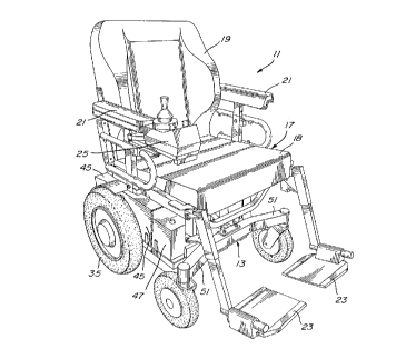
Fig. 1 is a perspective view of a motorized
wheelchair according to the invention;
Fig. 2 is a fragmentary exploded view of the
motorized wheelchair illustrating a detail
of the present invention;
Fig. 3 is a partial cross-sectional view taken
along line 3-3 of Fig. 2 illustrating a
further detail of the present invention;
Fig. 4A and 4B are cross-sectional views taken
along line 4-4 of Fig. 3 illustrating
different operative positions of the detail
shown in Fig. 4;
Fig. 5 is a partial side elevation of a wheelchair
according to the embodiment of Fig. 1; and
Fig. 6 is a side elevation similar to Fig. 5
illustrating the seating assembly of the
CA 02219430 1997-10-24
-- 6
wheelchair in a different operative
position.
In a preferred embodiment shown in Figs. 1 and 2,
the wheelchair 11 comprises a front T-shaped frame 13, a
rear T-shaped frame 15, a seat assembly 17, a backrest 19,
two armrests 21, two footrests 23 and a controller unit 25
to control independently or not the motors 27.
The rear T-shaped frame 15 is made of two short arms
29 and a first long arm 31. The long arm 31 defines a
longitudinal axis. The rear T-shaped frame 15 mounts two
motor supports 33 each of which mounts a motor 27 and a
wheel 35.
The wheels 35 of the rear frame 15 are mounted
either directly or indirectly via a speed reducer on the
motor 27. Each motor 27 is preferably operated by a battery
47.
Each motor support 33 includes a pair of arms 37a
and 37b which are telescopically inserted into one of the
two short arms 29 of the rear T-shaped frame 15. Each short
arm 29 has sub arms 29a and 29b presenting sockets to
accommodate arms 37a and 37b respectively. Therefore, the
distance between each motor support 33, and thereby the
wheels 35, may be adjusted allowing to reduce to a minimum
the width or bulk size of the wheelchair according to a
particular user. Each arm 37a and 37b of the motor support
33 are fixed within the sockets of arms 29a and 29b
respectively by means of a sliding block 39. The sliding
block 39 slides along the angled end 41 of either arm 37a
and 37b. The block 39 is loosened or tightened by a screw
43. This is similar to the locking device used to lock a
handle on a bicycle.
The rear T-shaped frame 15 further comprises a
protective plate 45 mounted under and in the rear of the
frame 15 to protect the motor 27 and to support two
batteries 47, one on each side of the wheelchair 11, for
each motor 27.
CA 02219430 1997-10-24
Two small stabilizer wheels 49 project from the rear
of the T-shaped frame 15 as shown in dotted lines in Fig. 2.
The front T-shaped frame 13 as shown in Figs. 1 to
4B has two short arms 51 and a second long arm 53 and
comprises two caster wheels 55, a connecting member 57 and
resilient members 59. Each caster wheel 55 is rotatably
mounted on one of the two short arms 51 of the front frame
13.
The connecting member 57 is adapted at one end to be
fitted around the second long arm 53 and at its other end to
be connected to the first long arm 31. The connecting
member 57 is fixed to the first long arm 31 in the same
manner as the arms 37 of the motor support 33 are fixed to
the rear frame 15. The connecting member 57 and the second
long arm 53 are preferably of square cross-section and are
sized to allow the second long arm 53 to rotate about the
longitudinal axis relative to the connecting member 57 when
the connecting member 57 is telescoped over the second long
arm 53. The connecting member 57 and the second long arm 53
each have a square cross-section but may be of any polygonal
cross-section.
The assembly of the second long arm 53 with the
connecting member 57 is illustrated in Figs. 3, 4A and 4B.
As apparent on Fig. 3, a U-clamp 69 is fixed at one end of
the second long arm 53. This U-clamp 69 is used to connect
with an arcuate tube at about its center, dividing that tube
in the two short arms 51 of the front frame 13.
The connecting member 57 is fixed within the first
long arm 31 with a sliding block 73. When the screw 75 is
rotated, the block 73 is pushed against the angled end 58 of
the connecting member 57 and slide away thereon, increasing
the effective cross-section of the connecting member 57 and
locking the same against the interior surface of the first
long arm 31.
As apparent on Figs. 4A and 4B, the second long arm
53 and the connecting member 57 each have a square cross-
CA 02219430 1997-10-24
-- 8
section. The second long arm 53 is inserted into the
connecting member 57 and is sized such that the diagonal
dimension of the square cross-section of the second long arm
53 is smaller than the interior width of the connecting
member 57.
The resilient members 59 are inserted between the
connecting member 57 and the second long arm 53 in such a
manner as to create a torque resisting the second long arm
53 rotation relative to the connecting member 57 which is
fixed to the first long arm 31 of the rear frame 15. When
the resilient members 59 are inserted between the second
long arm 53 and the connecting member 57, the rotation of
the second long arm 53 inside the connecting member 57 is
now restrained by the resilient members 59. In fact, the
longer the resilient members 59 extend between the second
long arm 53 and the connecting member 57, the stiffer is the
torque therebetween. Accordingly, the torque may be
adjusted with the length of the resilient member used.
Fig. 4A shows the relative position of the second
long arm 53 compared to the position of the connecting
member 57 when the wheelchair 11 is resting on even ground.
Fig. 4B shows again the relative position of same when one
of the caster wheels 55 is higher than the other. According
to Fig. 4B and the cross-section from which the figure is
taken, the left caster wheel 55 would be higher than the
right caster wheel 55.
The resilient members 59 are forced during assembly
between the connecting member 57 and the second long arm 53
creating friction therebetween and preventing the second
long arm 53 from sliding out of the connecting member 57.
Other means known to one skilled in the art are possible to
prevent the long arm 53 from sliding out of the connecting
member 57. For example, the connecting member 57 may be
provided with tongues that may interlock with further
tongues or grooves of the second long arm, in such a manner
CA 02219430 1997-10-24
g
as to prevent the connecting member and the arm from sliding
telescopically one into the other.
Such suspension system of the front caster wheels 55
in relation to the rear wheels 35 allows for rotation of one
set of wheels in relation to the other creating an angle a
between the two sets of wheels so that all the wheels
remains in contact with the ground in most conditions. This
angle a is preferably limited to + 30~. This rotation help
to reduce to a minimum the skidding of the inside powered
wheels (rear wheels 35) in a curve.
The seat assembly 17, as is illustrated in Figs. 1
and 2, comprises two rear seat supports 61, one on each side
of the wheelchair 11 and an arcuate front seat support 63.
The two rear seat supports 61 are provided with a series of
holes 65 to mount to different heights the rear seat
supports 61 to the rear frame 15, allowing for the back of
the seat assembly 17 to be raised or lowered. The front
seat support 63 is arcuate and is also provided with a
series of holes 67 to also mount to different heights the
front seat support 63 to the rear frame 15, allowing for the
front of the seat assembly 17 to be raised or lowered.
Accordingly, the seat assembly 17 may be inclined when the
rear seat supports 61 are fixed at one height and the front
seat support 63 is raised or lowered.
Figs. 5 and 6 show a preferred embodiment of the
invention. The seat assembly 117 has been modified to allow
for the seat 118 to be reclined and displaced forwardly to
maintain a good stability of the rider even when the latter
is reclined in the wheelchair. Normally, reclining a chair
displaces the center of gravity toward the rear of a chair.
However, with the seat assembly 117 according to this
embodiment, the center of gravity of the rider is not
affected by the reclining of the seat 118. Therefore, the
gravity center remains between the front and rear wheels
ensuring a good stability.
CA 02219430 1997-10-24
-- 10 --
According to Figs. 5 and 6, rails 77 define a frame
for the seat assembly 117 and are fixed to the rear frame
115. A sub frame 79 is used to secure the seat 118, the
backrest 119, the armrests 121 and the footrests 123. A
cylinder 81 having a piston 83 extending therefrom is
mounted to the rear frame 115. The piston 83 is connected
to a dog leg 163 at one end 163''. The dog leg 163 is
pivotably mounted at about its center to the sub frame 79.
The end 163' of the dog leg 163 is connected to the sub
frame 79. A rear end 79' of the sub frame 79 is connected to
the rail 77 to slide thereon. Accordingly, when the piston
83 is extended from the cylinder 81 as shown in Fig. 5, the
sub frame 79 and the seat 118 are in normal position, which
is about horizontal. When the piston 83 is retracted in the
cylinder 81 as shown in Fig. 6, the dog leg 163 pivots
clockwise around about its center to raise the end 163'
thereof. The end 163', being connected to the sub frame,
moves the latter upwardly and forwardly. However, since the
rear end 79' of the sub frame 79 can only move along the
rail 77, the rear end 79' of the sub frame 79 slides forward
as indicated by the arrow, reclining the seat 118 mounted
thereon and displacing the center of gravity of the user
between the wheels.
It is to be understood that the armrests 21 or 121
or the footrests 23 or 123 are optional and that any
armrests, footrests or any other accessories known in the
art may be used with the present invention.
While the invention has been described with
particular reference to the illustrated embodiment, it will
be understood that numerous modifications thereto will
appear to those skilled in the art. Accordingly, the above
description and accompanying drawings should be taken as
illustrative of the invention and not in a limiting sense.