Note: Descriptions are shown in the official language in which they were submitted.
CA 02219431 1997-10-27
W O96/33631 PCTAUS9610~289
VENTILATION STRUCTURE FOR A SHOE
BACRGROUND OF THE lNV~N-lION
The present invention relates to a novel and useful
ventilation structure for a shoe.
Myriad designs for footwear have been proposed in the
S past. In general, footwear is designed to protect the feet of the
user and is seasonable in nature. That is to say, footwear used in
hot weather is not often adaptable to cold weather use as well.
In past, shoe designs have been proposed which render
shoes usable for only hot weather or cold weather use. For
example, United States patents 2,235,490 and 4,333,248 describe a
shoe protector which is attachable to a shoe for the purpose of
protection of the shoe.
United States patents 2,200,080, 2,205,091, 2,345,187,
4,103,440, and British patent 874,066 all describe systems for
replacing the upper portions of shoes by detachment of the same
from the sole portion of the shoe. In many cases, zippers are
employed in this regard.
A system for ventilating a shoe and converting a shoe
structure from hot weather to cold weather use without complete
replacement of the upper portion would be a notable advance in the
clothing field.
SUBSTITUTE SHEET (RULE 26)
CA 022l943l l997-l0-27
W O96/33631 PCT~US96/05289
SUM~RY OF THE INVENTION
In accordance with the present invention a novel and
useful ventilation structure for a shoe is herein provided.
The ventilation structure of the present invention
utilizes a shoe having a sole portion that is connected to an upper
portion. An aperture is formed through the upper portion of the
shoe to provide communication between the exterior and the interior
of the shoe. The aperture may take the form of a single aperture
or a multiplicity of apertures formed about the perimeter of the
upper portion of the shoe. In any case, each of the apertures is
fitted with a mesh layer connected to the upper portion of the shoe
and in overlying relationship with any of the apertures formed in
the upper portion of the shoe. Closure means in the form of
zippers may be employed to shut at least a portion of the each of
the apertures to block the movement or convection of air from the
exterior to the interior of the shoe. The closures in the form of
zippers may include multiple sliders for this purpose.
When any of the apertures are closed or shut, a chamber
may be formed between the shut aperture and the overlying mesh
layer. In such a case, a partition of solid material may be placed
within the chamber to further block moisture and convection
currents, especially ones moving from the exterior to the interior
of the shoe.
Moreover, an opening in the toe portion of the shoe may
be formed at a distance which is greater from the sole portion of
the shoe than any of the prior described apertures. The toe
CA 02219431 1997-10-27
W O96/33631 PCTrUS96105289
portion opening may also be formed with an overlying mesh layer and
include a flap which is movable f~om an open to a closed position,
and may be fixed in either one of these positions. Thus, cross
ventilation is created between any one of the apertures and the toe
portion of the shoe.
It may be apparent that a novel and useful ventilation
structure for a shoe has been heretofore described.
It is therefore an object of the present invention to
provide a ventilation structure for a shoe which includes apertures
which permit ventilation within the upper portion of the shoe and
yet provides an overlying mesh layer which serves to block solid
objects, such as rocks, sand, insects, and the like from entering
the interior of the shoe.
Another object of the present invention is to provide a
ventilation structure for a shoe which tends to scoop or pump air
through apertures in the shoe during normal walking by the wearer
of the shoe.
A further object of the present invention is to provide
a ventilation structure for a shoe which provides a plurality of
openings and apertures to create cross ventilation which is
especially useful in extremely hot weather.
Yet another object of the present invention is to provide
a ventilation structure for a shoe which obviates the need to wear
multiple sets of shoes depending on the weather conditions
encountered by the user of the shoes.
Another object of the present invention is to provide a
CA 02219431 1997-10-27
W O96/33631 PCTrUS96/05289
ventilation system for a shoe which may be quantitatively adjusted
according to the determining weather conditions and permits the
user to either walk or run.
Yet another object of the present invention is to provide
a ventilation structure for a shoe which results in a shoe having
an aesthetic appearance not unlike shoes of conventional
configuration.
The invention possesses other objects and advantages
especially as concerns particular characteristics and features
thereof which will become apparent as the specification continues.
CA 022l943l l997-l0-27
W O96/33631 PCTnUS96/05289
BRIEF DESCRIPTION OF THE DRAWINGS
FIG. 1 is a top right perspective view of an embodiment
of the present invention.
FIG. 2 is a top right perspective view of the embodiment
of the invention depicted in Fig. 1 with the zipper portion open.
FIG. 3 is a sectional view taken along line 3-3 of Fig.
1.
FIG. 4 is a sectional view taken along line 4-4 of Fig.
2.
FIG. 5 is another embodiment of the invention depicting
a partition in the chamber shown in Fig. 3.
FIG. 6 is a top right perspective view of yet another
embodiment of the present invention.
FIG. 7 is a top right perspective view of yet another
embodiment of the present invention.
FIG. 8 is a top right perspective view of the embodiment
depicted in Fig. 7 with the flap portion in an open position.
FIG. 9 is a sectional view taken along line 9-9 of Fig.
8.
FIG. 10 is a schematic top plan view of yet another
embodiment of the present invention.
FIG. 11 is a schematic top plan view of yet another
embodiment of the present invention.
For a better understanding of the invention references is
made to the following detailed description of the preferred
embodiments thereof which should be taken in conjunction with the
CA 02219431 1997-10-27
PCT~US96/05289
W 096/33631
hereinabove described drawings
CA 02219431 1997-10-27
W O96/33631 PCTrUS96/05289
DETAILED DESCRIPTION OF THE PREFERRED EMBODIMENTS
Various aspects of the present invention will evolve from
the following detailed description of the preferred embodiments
which should be referenced to the prior described drawings.
The invention as a whole is depicted in the drawings by
reference character 10 and an upper case letter denoting various
embodiments of the same. Fig. 1 depicts embodiment 10A of the
invention in which a shoe 12 is depicted having an upper portion 14
and a lower portion 16 including a sole 18 and a heel 20.
Ventilation structure 10A includes an aperture 22 formed in the
upper portion 14 of shoe 12. Aperture 22, Fig. 1 takes the form of
a slit which extends from the right side of shoe 12, about toe
portion 24, and to the left side of shoe 12. Aperture 22 extends
from the exterior of shoe 12 to the interior 26, thereof. Thus,
convection currents may pass through shoe 12 in this regard. With
reference to Fig. 2, it may be observed that mesh layer 28 is
fastened to the interior surface 30 of upper portion 14 of shoe 12,
by any suitable means such as gluing, sewing, stapling, and the
like. Thus, solid objects are prevented from passing from the
exterior to the interior 26 of shoe 12. Mesh layer 28 may be of
any suitable size and structure. For example, mesh layer 28 may be
formed of nylon, cotton, and other suitable materials. Mesh layer
28 is necessarily flexible and preferably soft.
Closure means 32 is also depicted in the present
invention to shut at least a portion of aperture 22. Turning to
Figs. 3 and 4, it may be observed that closure means takes the form
CA 02219431 1997-10-27
WO 96/33631 PCT/US96/0~289
of a zipper 34 having sliders 36 and 38 which close tooth portion
40 in a conventional manner. Of course, other closure means may be
employed such as Velcro fasteners, snaps, and the like. Fig. 4
shows zipper 34 in an open position along aperture 22. It should
be noted that chamber 42 is formed between zipper 34 and mesh layer
28. Turning to Fig. 5, it may be observed that partition 44 has
been inserted within chamber 42 in order to positively block
moisture and/or convection currents passing through zipper teeth
40. This is especially useful in windy and cold weather. In other
words, partition 44 may be employed to winterize embodiment lOA, or
when zipper 34 is not opened for long periods of time.
Turning to Fig. 6, it may be apparent that another
embodiment lOB is the ventilation structure of the present
invention is depicted. Structure lOB includes an aperture 46 which
is rather short on upper portion 14 of shoe 12. Zipper 48
including sliders 50 and 52 permit ventilation to enter the
interior 26 of shoe 12 only through the side of upper 14, and to a
degree dependant on the opening allotted by zipper 48. Mesh layer
54 overlies aperture 46 and is fastened in a manner similar to that
depicted with respect to mesh layer 28 and aperture 22, Figs. 1-5.
Fig. 7 shows yet another embodiment lOC of the present
invention in which shoe 12 includes the aperture 46 and zipper 48
found in Fig. 6 with respect to embodiment lOB. However, an
opening 56 of roughly a semi-oval construction has been formed in
the toe portion 24 of shoe 12. Opening 56 is further from sole 18
than aperture 46. Opening 56 is fitted with a mesh layer 58 which
CA 022l943l l997-l0-27
W O96/33631 PCTrUS96/05289
is attached to upper portion 14 of shoe 12 by sewing, gluing,
riveting, and the like. A flap 60 is held to the upper 14 of shoe
12 by rivet 62 and is capable of rotating into an open or closed
position. Fig. 7 shows flaps 60 in a closed position while Fig. 8
illustrates flap 60 being in an open position. Plurality of hook
and pile closures 64 and 66 on toe portion 24 of shoe 12 and flap
60, respectively, permit the closure of flap 60 in the position
shown in Fig. 7. Flap 60 may be fastened in an open position as
shown in Fig. 8 by the use of plurality of hook and pile fasteners
68 and corresponding hook and pile fasteners, such as exemplary
hook fastener 70 formed on the upper portion 14 of shoe 12, Fig. 7.
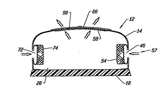
Turning to Fig. 9, it may be apparent that apertures 46
and 72, overlain by mesh layers 54 and 74, respectively, are formed
on the right and left sides of shoe 12 upper portion 14. With flap
60 in the open position, ventilation currents may pass through
apertures 46 and 72 and out opening 56 according to directional
arrows 57 on Fig. 9. However, such ventilation may be reversed by
the natural walking motion of the user which tends to pump air in
an out of the interior 26 of shoe 12, in which case arrows 56 would
be reversed in orientation.
Fig. 10 and Fig. 11 schematically represent embodiments
lOD and lOE in which shoe 12 includes an aperture 72 which travels
from the right side, around toe portion 26 and to the left side of
shoe 12, Fig. 10. Embodiment lOD includes a quartet of sliders 74
with respect to zipper structure 75, Fig. 10. Embodiment lOE, Fig.
11, includes a pair of apertures 76 and 78 having zipper structures
CA 02219431 1997-10-27
W O96/33631 PCTrUS96/05289
80 and 82, which do not extend around the toe portion 26 of shoe
12. Zipper structures 80 and 82 each include a pair of sliders 84
and 86, respectively. In the embodiments depicted in Figs. 10 and
11 apertures 72, 76, and 78 are each fitted with mesh layers t
5similar to those shown with respect to aperture 22 of Fig. 1.
In operation, the user of embodiments lOA-lOE would open
the apertures using the particular zipper structures shown in the
drawings to a degree permitting adequate ventilation to the
interior 26 of shoe 12. In addition, air would pass through any of
10the apertures shown in the embodiments lOA-lOE by the normal
walking action associated with the user of shoe 12. In extremely
cold and/or windy weather, partition 44 may be employed, Fig. 5 to
more positively seal aperture 22. Moreover, partition 44 may be
waterproof to prevent moisture from entering interior 26 of shoe
12. Vent opening 56 and toe portion 26 of shoe 12 is also employed
in conjunction with any one of the apertures formed along sides of
upper portion 14 of shoe 12 closer to sole 18. Flap 60 may be
opened or closed to permit such cross ventilation as depicted in
Fig. 9 of the drawings. It has been found that the ventilation
20structures lOA-lOE are versatile in use and permit the user of shoe
12 to wear the same in a variety of weather conditions.
While in the foregoing, embodiments of the present
invention have been set forth in considerable detail for the
purposes of making a complete disclosure of the invention, it may
25be apparent to those of skill in the art that numerous changes may
be made in such detail without departing from the spirit and
CA 02219431 1997-10-27
W O96/33631 PCTrUS96/05289
principles of the invention.