Note: Descriptions are shown in the official language in which they were submitted.
CA 02219547 2001-09-21
-1-
Description
Field of Invention
This invention relates generally to a method and an apparatus for extruding an
elongated article having a cross-sectional profile that varies along its
length. This invention
further relates to an article of manufacture comprising an extruded
thermoplastic rod having
a variable cross-sectional profile, and a further article of manufacture
comprising a
thermoplastic tube having a variable cross-sectional profile.
Background of Art
Extruders used to produce objects made of extrudable materials are well known.
Such
extruders generally comprise a hopper through which an extrudable material is
introduced
into the extruder; a heating element to melt the extrudable material if such
material is a
thermoplastic; and an aperture or die through which the extrudable material is
extruded.
There is a need to produce extruded objects having a cross-sectional profile
that varies
along its length by varying the size and shape of said aperture during the
extrusion process.
An extruder die having such a variable means for defining an aperture, shaping
means allows
the extrusion, for example, of thermoplastic articles such as baseball bats,
bowling pins,
water toys and the like.
Means for extruding articles having a cross-sectional profile that varies
along its
length is also known.
U.S. Patent No. 2,578,229 teaches a draw plate comprising a series of
interlocked
jaws defining a polygonal opening and means for adjusting the size of such
opening so as to
provide varying cross-sections for drawn members such as rods, bars and tubes
and the like.
Means for shaping and cutting spherical objects from dough are also disclosed
in U.S.
Patent Nos. 4,734,024, 5,153,010 and 5,190,770.
CA 02219547 1997-10-29
-2-
U.S. Pat. No. 4,734,024 relates to an apparatus for shaping a round body
consisting
of dough and filling. Said apparatus contains a cutter assembly having at
least three
circumferentially disposed cutter members arranged in sliding contact with
each other so as
to form a central aperture. Said central aperture is openable for receiving a
leading part of
a cylindrical body of dough and filling, and closable for shaping the received
part into a
shaped body substantially polygonal in form and severing it from the remainder
of said
cylindrical body of dough and filling.
U.S. Patent No. 5,153,010 teaches an improved apparatus for cutting and
shaping a
spherical form made of dough with a filling. Said apparatus has a structure
capable of
accommodating a greater number of shaping members, hence, allowing dough to be
a shaped
into a form that is more substantially spherical than in U.S. Patent No.
4,734,024. Said
improved apparatus comprises a plurality of identically shaped polygonal
members, each of
which having a first end pivotally connected to one of a plurality of supports
which are
disposed equidistantly around a circular opening, and which polygonal members
collectively
define an aperture. Each of said polygonal members has a tip, first curved
side and second
curved side. When said polygonal members are in the open position, the first
curved side
of each of the polygonal members abuts said second curved side of the adjacent
polygonal
member. When said polygonal members are in the closed position, said tip of
each of the
polygonal members is disposed at the central point of said circular opening.
Similarly, U.S. Patent No. 5,190,770 discloses another apparatus for cutting
and
shaping a spherical body which is particularly adapted to forming spherical
articles from
dough. The apparatus taught therein discloses a plurality of identically
shaped cutting and
shaping members, one end of each of the members being pivotally fitted to each
of a
plurality of fulcrums that are equidistantly disposed on an imaginary
circumference formed
by connecting said fulcrums, and the opposite end of each of said shaping
members being
formed into a tip so that said shaping members collectively and radially form
and close an
opening concentric to the circumference surrounded by said shaping members
when each of
said shaping members pivots away from and towards the centre of the
circumference,
respectively, thereby to cut and shape the dough passing through said opening.
CA 02219547 1997-10-29
-3-
Variable closure means more particularly adapted for extruding thermoplastic
articles
are also known.
U.S. Patent No. 3,932,090 discloses an apparatus for extruding articles having
integral ribs and/or integral rows of spaced apart elements extending
transverse to the
direction of extrusion by extruding melt flowable material in a first annular
extrusion zone
while the melt flowable material being extruded in a second annular extrusion
zone is
periodically interrupted, modulated and/or restricted.
U.S. Patent No. 4,187,068 teaches an apparatus for extruding an elongated
article
having a cross-sectional profile which varies along its length comprising a
die plate,
stationary die block and plurality of die members. Said die members and
stationary die block
are mounted on said die plate and form together an orifice. A controllable
drive means is
also provided for to allow said die members to be moved contemporaneously
along channels
so as to modify the shape and size of said orifice.
It is an object of this invention to provide for a more efficient and simple
apparatus
for producing elongated articles from extrudable materials, comprising an
extruder, first
retaining member, second retaining member, sealing means and moveable means
for defining
an aperture disposed between said first and second retaining members. It is
still a further
object to provide for a process for extruding an elongated article having a
cross-sectional
profile that varies along its length by heating a melt flowable material in an
extruder,
extruding said melt flowable material through a moveable means for defining an
aperture,
and sealing said moveable means to said extruder. Finally, it is also an
object of this
invention to provide for an elongated article extruded from a thermoplastic
material having
a cross-sectional profile that varies along its length.
The moveable means for defining an aperture used in the present invention
comprises
an iris. The iris allows the shaping of objects that are more substantially
spherical in shape
than the apparati disclosed in the prior art, particularly U.S. Patent No.
4,187,068.
Furthermore, the cross-sectional profile of the aperture defined by said iris
can be modified
during the extrusion process with greater ease and speed than the controlling
drive means and
channels disclosed in U.S. Patent No. 4,187,068 which in turn allows more
efficient
CA 02219547 1997-10-29
-4-
extrusion of elongated articles having a cross-sectional profile, and also
permits greater
variance of the cross-sectional profile of such elongated articles along their
length when the
same are extruded continuously. The iris used in the present invention also
has cost
advantages over other variable closure means disclosed in the prior art.
Disclosure of Invention
It is a first aspect of this invention to provide for an apparatus for
extruding an
elongated article having a cross-sectional profile that varies along its
length, comprising an
extruder, moveable means for defining an aperture and sealing means mounted
between said
extruder and said moveable means.
In accordance with yet another aspect of the invention, to provide for an
apparatus
for extruding an elongated article having a cross-sectional profile that
varies along its length,
comprising an extruder, first retaining member, second retaining member,
moveable means
for defining an aperture, and sealing means disposed between said first and
second retaining
members.
In accordance with still another aspect of the invention, to provide for an
apparatus
for extruding an elongated article having a cross-sectional profile that
varies along its length,
comprising an extruder having an orifice for heating a thermoplastic material
to form an
extrudable thermoplastic foam; moveable means for defining an aperture
communicating with
said orifice so as to open and close said orifice; first retaining member
having a first hole
therethrough; second retaining member having a second hole therethrough, said
first retaining
member threadably engageable with said second retaining member so as to retain
said
moveable means; and sealing means consisting of an o-ring.
In accordance with a further aspect of the invention, to provide for a process
for
extruding an elongated article having a cross-sectional profile that varies
along its length,
which comprises introducing an extrudable material into an extruder,
discharging said melt
flowable material through moveable means defining an aperture, and sealing
said moveable
means to said extruder.
CA 02219547 1997-10-29
-5-
In accordance with a further aspect of the invention, to provide for a process
for
extruding an elongated article having a cross-sectional profile that varies
along its length,
which comprises heating a thermoplastic material in an extruder to form a
thermoplastic
foam; extruding said thermoplastic foam through a first retaining member which
is threadably
connected to a second retaining member and wherein a sealing means and
moveable means
defining an orifice are disposed between said members; and extruding said
thermoplastic
foam to form an elongated article having a cross-sectional profile that varies
with said
varying aperture.
In accordance with a further aspect of the invention, to provide for an
article of
manufacture which consists of a thermoplastic rod having a cross-sectional
profile that varies
along its length.
In accordance with yet further an aspect of the invention, to provide for an
article of
manufacture which consists of a thermoplastic tube having a cross-sectional
profile that varies
along its length.
Brief Description of Drawings
Fig. 1 is an exploded view of moveable means for defining an aperture.
Fig. 2 is a perspective view of said moveable means in closed position.
Fig. 3 is a perspective view of said moveable means in open position.
Fig. 4 is a cross-sectional view of the apparatus.
Fig. 5 is a view of bats made by the process and apparatus.
Fig. Sa is an alternate embodiment of the bats made by the process and
apparatus.
Best Mode for Carrying Out the Invention
In the description which follows, like parts are marked throughout the
specification
and the drawings with the same respective reference numerals. The drawings are
not
necessarily to scale and in some instances proportions may have been
exaggerated in order
to more clearly depict certain features of the invention.
CA 02219547 1997-10-29
-6-
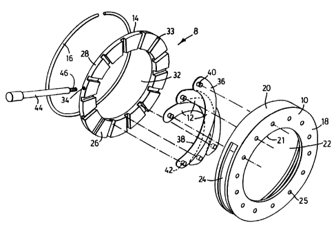
Fig. 1 shows an exploded view of the moveable means for defining an aperture
8.
Said moveable means contains a first ring 10, a plurality of elongated, curved
members 12,
a second ring 14, and a retainer 16. Said first ring 10 has a front wall 18, a
side wall 20,
a first ring orifice 21 and a first ring opening 22. Said side wall 20
contains a side opening
24 which is parallel with the circumference of said front wall 18. Said first
ring front wall
18 contains a plurality of locating holes 25. Said second ring 14 comprises a
front wall 26,
a side wall 28 and a second ring opening 32. Said second ring front wall 26
contains a
plurality of radially disposed locating grooves 33. Said side wall 28 contains
a shaft hole 34,
further described below.
Each of said elongated members 12 has a front side 36 and a back side 38. Each
of
said elongated members 12 has a front pin 40 at one extremity of said front
side 36 and a
back pin 42 at the opposite extremity of said back side 38. Each of said front
pins 40
communicates with said locating holes 25, so as to permit said elongated
members 12 to be
rotatably connected to said first ring 10. When said elongated members 12 are
rotatably
connected to said first ring 10, said elongated members 12 overlap.
Said second ring 14 is slightly smaller than said first ring 10, accordingly,
said second
ring 14 can be fitted into said first ring orifice 21 and is held in place by
retainer 16. Once
said elongated members 12 are connected to said first ring 10, said second
ring 14 is fitted
into said first ring orifice 21 so that said back pins 42 communicate with
said locating
grooves 33. A shaft 44 having threadable end 46 can be screwed into said shaft
hole 34
through side opening 24.
When shaft 44 is moved between the two extremities of said side opening 24,
said
second ring 14 is rotated within said first ring orifice 21. Said rotating
motion of said second
ring 14 within said first ring orifice 21 causes said front pins 40 to rotate
in said locating
holes 25 contemporaneously so that said elongated members 12 are radially
displaced around
said locating holes 25, while said back pins 42 slide within said locating
grooves 33 so as
to, in combination, open and close a variable aperture.
Fig. 2 shows a perspective view of the moveable means for defining an aperture
8
shown in Fig. 1 which has been fitted into casing 50. Said casing 50 contains
a casing
CA 02219547 2001-09-21
_7-
locating notch 52 and casing annular recess 53. Said Fig. 2 shows the aperture
in a closed
position.
Fig. 3 shows a perspective view of the moveable means for defining an aperture
shown in Fig. 2 in an open position.
Fig. 4 shows a cross-sectional view of the extruder 54. Said extruder 54
contains
extruding member 56, first die block 58 and extruder die 59. In the embodiment
shown in
Fig. 4, said first die block 58 is connected to said extruding member 56 by
means of a
plurality of screws such as screws 60 and 62 which engage a plurality of screw
holes such
as screw holes 64 and 66 disposed in said first die block 58 which screw holes
64 and 66
communicate with corresponding screw holes 65 and 67 disposed in extruding
member 56.
First die block 58 has an extrusion orifice 70 and a die front wall 71.
The embodiment of the invention shown in Fig. 4 is adapted to discharging
extrudable
materials that are melt flowable. Plastic elements, for example, are poured
into extruder
hopper 72 which communicates with extruder hopper opening 74 disposed in said
extruding
member 56. Said extruder hopper opening 74 communicates with extruder barrel
75. Fig.
4 shows schematically a heating element 76 to heat, for example, plastic
pellets to an
appropriate temperature in a manner well-known to those skilled in the art, so
as to produce
a thermoplastic material in an extrudable form. Means for retaining said
moveable means
for defining an aperture 8, or retaining member(s), are generally illustrated
herein as first
retaining member 78 and second retaining member 80.
Extruder die 59 also contains a first retaining member 78 and a second
retaining
member 80. First retaining member 78 contains a conical hole 82 which
communicates with
extrusion orifice 70. Said first retaining member 78 also contains a back wall
84, a side wall
86, front wall 88, annular recess 89, larger cylindrical protrusion 90, and
smaller cylindrical
protrusion 92.
Said larger cylindrical protrusion 90 extends from inside annular recess 89.
Larger
cylindrical protrusion 90 has a first protrusion side wall 94 which is
threaded, and a first
protrusion front wall 96. Smaller cylindrical protrusion 92 extends from said
first protrusion
CA 02219547 2001-09-21
_g_
front wall 96 and has a second protrusion front wall 100. Said second
protrusion front wall
100 has an annular groove 101 for accommodating sealing means 102 and a bore
104.
Said first retaining member 78 is connected to said first die block 58 by
means of a
plurality of screws such as screws 103 and 105 which engage a plurality of
screw holes such
as screw holes 106 and 107 located on said first retaining member front wall
88 which
correspond with a plurality of screw holes such as screw holes 108 and 110
located on said
die front wall 71.
Said second retaining member 80 contains a front face 112 and a lateral wall
114.
Said front face 112 has a conical recess 116. Lateral wall 114 has a
longitudinal opening 118
for accommodating said shaft 44 of said moveable means defining an aperture 8.
The inside
of front face 112 has a round protrusion 120 and a locating cavity 122. Said
casing annular
recess 53 registers with round protrusion 92, and said casing locating pin 52
registers with
said locating cavity 122 so as to allow said moveable means for defining an
aperture 8 to be
mounted on the inside of said front face 112.
The inside of lateral wall 114 is threaded so as to allow said second
retaining member
80 to be threadably connected to said first retaining member 78, thus
mechanically engaging
said moveable means for defining an aperture 8 and said sealing means 102
between said first
retaining member 78 and second retaining member 80, so as to prevent seepage
of said
melted thermoplastic material when said thermoplastic material is extruded
through the
variable aperture.
In operation, thermoplastic material is introduced into hopper 72 and heated
by
heating means 76 and shaped or extruded. The thermoplastic material is
extruded through
the variable apparatus to shape or extrude a rod of material having a variable
diameter as
shown in Fig. 5. The method and apparatus described herein can be used to
produce a
number of products including foam bats 100 which may be connected together by
a web 123
or designed adjacent one another as shown in Fig. 5a. If a web 123 is used or
if the bats are
adjacent one another the bats may be severed in a severing step. In operation
the shaft 44 may be
connected to a linkage to a motor (not shown) so as to cause the shaft 44 and
thus the apparatus to
open and close in a sequence to produce the desired products. The linkage may
include caroming
CA 02219547 1997-10-29
-9-
lobes to open and close the apparatus in an asymmetric manner to produce for
example the
bat. Other examples of products that can be made include water toys such as
foam water
logs, swing set coverings - foam tubing for covering swing sets and one could
produce
variable outside diameters for decorative purposes, custom packaging profiles
to cradle parts
during shipping, foam baseball bats and bowling pins for children, toilet tank
floats, neck
support cushions, fishing floats and pool and beach safety line floats.
The embodiment of the invention depicted in Fig. 4 and described in detail
above is
particularly adapted for extruding rod-like products. The disclosed invention,
however, is
also adaptable to extruding a variety of tubular members having a variable
outer diameter by
placing, for example, a mandrel in the extruder 54 upstream from said moveable
means
defining an aperture 8, in a manner well-known to those skilled in the art.
Various embodiments of the invention have now been described in detail. Since
changes in and/or additions to the above-described best mode may be made
without departing
from the nature, spirit or scope of the invention, the invention is not to be
limited to said
details .