Note: Descriptions are shown in the official language in which they were submitted.
uc~ u pa~ K ~ ng l aw Ott l ce 4~ ~ -
CA 02219696 1997-10-30
roR~n ~CK ~Y~
BACKGROUND OF ~ J INVENTION
s
1. Fiel~ of the ~nV~ntion~ This invention relates to apparatus and
methods for loading and unloading ladders and the like from ladder racks
on vehicles.
2. Prior A~t. Large pieces of equipment such as ext~ncion ladders
are transported by service per30nnel for utility, telephone, and cable TV
operators in fixed racl~ on the roofs of service vehicles, such as vans or
truck~. I,o~clin~ and ~l~ln~flin~ of ladders from the3e fixed rack~ requires
awkward lifting of heavy, cumbersome ladders, which may result in
15 damage to the vehicle or the ladder as well as strain or injury to a service
person.
Consequently, the need has arisen for improved apparatus and
methods for loading and unloadin~ long items such as ladders from racks
2 0 on vehicles.
TGR003/APLN/PTK
~JCt ~ ~u pa L ~~ l ng ~ aw o~ r ~ ~e ~u~ c~ 3 - o ~ r
CA 02219696 1997-10-30
S U M M ~RY O F TF~F, n~r~,r~TIO N
It is therefore an object of the invention to provide im proved
apparatu~ and methods for loading and unlo~ing ladder~ and the like
5 ~om racks on vehicles.
In accordance with this and other obiects of the invention, a
vehicular ladder loader system for loading and llnlo~rling ladderff from a
rack on a vehicle is provided. 11he ~ystem include6 a static rack for holding
1 0 one end of a ladder and a pivoting and extendible rack for holAin~ the other end of the ladder.
The static rack i5 mounted to the roof of a vehicle and ha~ a pair of
upwardly extending ladder grip~, each of which is located near a respective
1 5 side rail of the ladder near the one end of the ladder.
The system further include~ a pivotable and extendible ladder rack
assembly. The pivotable and extendible ladder rack assembly include~ a
base member mounted to the roof of a vehicle, an elongated pi~oting
2 0 member, and a elideable ladder carriage member. The elongated pivoting
member i~ pivotably mounted to the ba~e rnember and has an inboard
ladder grip located at one end which i9 adapted for engagement with one
side rail of the ladder at the other end of the ladder. The slideable ladder
carriage member ~lideably extend~ from the other end of the elongated
2 5 pivoting member. The slideable ladder carriage member at it~ outer, or
distal, end ha~ an outboard ladder grip mounted thereto which is adapted
TGR003/APLNJPTK 2
Oct-30-~37 11~50 pat ~ing law o-rf~ce 40~ 685-~1C15
CA 02219696 1997-10-30
for engaging the other side rail of the ladder also near the other end of the
ladder. The slideable ladder carriage member retracts into the elongated
pivoting memb~r ~uch that the respective inboard and outboard ladder
grips are ~paced to enga~e the respective ~ide rails of the ladder near the
S other end of the ladder. The ~slirlePhle ladder carriage member is extendible
from the pivoting member ~uch that the respective inboard and outboard
ladder grips can be ~paced ~urther apart than the width of the ladder.
The pivotable and PYtsr~dible l~dder rack ~3embly has a first locked-
10 down, home position in which the elongated pivoting member ishori~ontally positioned on top of the vehicle and in which the slideable
]adder carriage member is retracted into the pivotable slideable carriage
member so that the ladder grip of the pivoting member and the ladder grip
of the slideable ladder c~rriage member hold the ladder in a horizontal
I 5 po~ition on the roof of the ~ehicle.
The pivotable and extendible ladder rack ~emhly has a second fully-
til~ed, but not extended7 po~ition in which the elongated pivot~ng member IS
pivoted at an acute angle with respect to the base while the sliding member
20 r~m~in~ retracted into the pivoting member so that the ladder is held in
position between the inboard and outboard ladder grip8;
The pivota~le and eYtenrlihle ladder rack ~8~mhly has a third fully-
tilted and extended position in which the elong~ted pivoting mem~er is
2 5 pivoted to extend at all acute angle with re~pect to the base and in which the
~lidea~le ladder curriage member is extended outwardly from the pivoting
TGK0031APLN/PTK 3
Oct-30-97 11:50 pat king law office 408 685-olO5
CA 02219696 1997-10-30
member so that the ladder rest~ against the outboard ladder grip of the
slideable ladder carriage member and the ladder grips are ~paced apart to
permit removal from and placement on the slideable ladder carriage
member of a ladder.
The system i8 provided with a mech~niYm for positioning the
pivotable ant extendible ladder rack as~ernbly in the first locked-down
position. A mechanism is provided for po~itioning the pivotable and
extendible ladder rack assembly in the second fully-tilted, but not extended,
10 position. A mech~ni.~m i~ provided for releasing the slideable ladder
carriage member ~uch that the pivotable and extendible ladder rack
assembly assumes the third fully-tilted and extended position.
A cable is coupled to the one end of the pivoting member and a cable-
15 spooling mech~ni~m pays out and reels in the cable for po~itioning themotorized ladder ~ack assembly in the first locked-down po~ition. The
mec~qnicm for positioning the motorized ladder rack assembly in the
second fully-tilted position include~ a bi~in~ member which biases the
pivotable ~lideable carriage member to the fully-tilted position. The
2 0 mech~niRm for positioDing the motorized ladder rack assembly in the
secont ~ully-tilted po~ition also includes the cable-spooling me~h~ni~m for
paying out the cable coupled to the pivoting member. In one embodiment of
the i~lve-ltion, the biaaing member includes one or more pneumatic struts.
TGR003~APLN/PTK 4
~JCt~ 31 pat ~ng law Ott~ Ot~ Cl~ r .V~J
CA 02219696 1997-10-30
The mech~ni~m for positioning the motorized ladder rack assembly
to the third fully-ti}ted and downwardly-telescoped position includes the
cable and the cable-spooling mech~ni~m for ~urther paying out the cable.
S The cable-spooling me~h~ni~In includes a spool driven by a l~ve~ le
motor. A cable tension sensor senses reduced tension in the cable and
disable~ the motor in response to reduced tension in the cable. The cable
tension ~ensor includes a spring-loaded pivotable lever arm having an idler
roller at one end for cont~ctinF the cable and a stop member at the other end
for interrupting a photocell when the cable tension i~ reduced.
A safety latch mechanically locks the one end of the elongated
pivoting member to the base when the motoIized ladder rack assembly i9 in
the ~lrst locked-down, home position. The safety latch include~ a spring-
loaded hool~ which i8 connected to a cable connected to a mechanically
positioned control member. The mecha~ically po~itioned control member
includes a rotatable spring-]oaded, center-positioned control member with a
wiper attached thereto which interrupts a photocell coupled to a controller
for the motor.
The mecl~ni.~m for positioning the motorized ladder rack assembly
to the first locked-down poeition includes a shaft encoder connected to the
motor for ~en~ing rotation of the pulley, an integrated circuit controller
wh~ch ~enses the length of the cable and remembers the home position (as
indicated with a green LED) and shut~ off the ~y~tem after 30 second
TGR0031APLN~PTK 5
Oct-30-~37 11:51 pat king ~law office 408 685-6105 ~ o,
CA 02219696 1997-10-30
timeouts, a relay which switche3 the motor polarity at the end of ~ cyc}e,
and d) an audible ~ignal which sounds during operation.
The upwardly extending ladder grip~ of the static rack extend
forwardly and sidewardly at angles with respect to vertical.
The ~lideable ladder carriage member includes a telescoping
member which telescopes into the pivotable slideable carriage member.
The ~lideable ladder carriage rnember has a stop po~t adapted to prevent the
1 0 ladder from slitlin~ fore and aft with respect to the vehicle.
The invention provides a method of loading a ladder on a vehicle
including the step& of: engaging respective side rails of a ladder near one
end of the ladder with a static rack having a pair of upwardly exte~lin~
ladder grip~; holding the other end of the ladder in a first locked-down
home position with a slideable carriage member which is ~lideably
mounted to an elongated pivoting member which is horizontally positioned
on top of a vehicle and which ifi retracted into the elongated pivoting
member; gripping the one ~ide of the other end of the ladder with an
2 0 inboard ladder grip mounted to the elongated pivoting member and
gripping the other side of the other end of the ladder with an outboard
ladder grip mounted to the slideable carriage member so that an outboard
ladder grip di~tal end of the slideable carriage member i~ in it~ closest
po~ition with respect to an inboard ladder grip on the elongated pivoting
member ~o that the ladder grips are holding the ladder in a hori~ontal
position on the roof of the vehicle; pivoting the elongated pivoting member
TGR003JAPLNJPTK 6
Oct-30-97 11:51 pat king ~aw office 4C~ 105 ~ u~
CA 02219696 1997-10-30
from the first locked-down home position to a ~econd fully-tilted, but not
tele~coped, po~ition in which the elongated pivoting member is pivoted to
extend at an acute angle with re~pect to ho~izontal while the slideable
carriage member re~ins retracted into the elongated pi~oting member so
5 that the ladder is tilted with respect to horizontal and the inboard and
outboard ladder grips remain holding the other end of the ladder; and
extending the slideable carriage member from the second po~ition
downwardly to a third fully-tilted and do~llwardly-telescoped position in
which the pivoting slideable carriage member rem~in-s pivoted to ex~end at
10 an acute ~ngle with respect to horizontal and the alideable carriage
member is extended downwardly and outwardly from the other end of the
pivotable slideable carriage member so that the ladder grip at the first end
of the pivotable slideable carriage member is in its farthest position with
respect to the ladder gTip of the ~ lin~ member so that the inboard ladder
1 5 grip is located away from the other end of the ladder to release the ladder
for removal.
The method further includes the steps of biasing the pivotable
slideable carriage member toward the ~ully-tilted position; biasing the
2 0 pivotable slideable carriage member toward the fully-tilted position with 8
pneumatic etrut; and r~le~in~ a cable connected to the first end of the
pivotable slideable carriage member to release the pivotable slideable
carriage member from the fir3t locked-down position.
2 5 The step of exten~ the slitle~hle carriage member from the second
position downwardly t~ a third fully-tilted and downwardly-telescoped
TGR003/APLN~PTK 7
Oct-30-~7 11:31 pat king law or~lc~ ~ ~3-OlU:~ r
CA 02219696 1997-10-30
po~ition includes exten~lin~ the sliding mem~er t3 and from the second
fully-tilted, but not telescoped, position to the third fully-tilted and
downwardly-tele~coped position using ~ cable connected at one end to the
~lideable camage member.
The ~tep of holding the other end of the ladder in a first locked-down
home position include~ the ~tep of positioning the motorized ladder rack
a~sembly in the first locked-down position using a cable coupled to the one
end of the pivoting member and a cable-6pooling me~h~ni~m for p~ying out
l 0 and reeling in the cable.
The fitep of pivoting the elongated pivoting member from the first
locked-down home position to a second fully-tilted, but not telescoped,
po~ition includes bi~Rin~ the pivotable ~lideable carriage member to the
l 5 fully-tilted position using a pneumatic strut and paying out the cable
coupled to the pivoting member using a cable-spooli~g merhS~niRm.
The step of ~lrten~iinE the filirl~ble carriage member from the second
position downwardly to a third fully-tilted and downwardly-telescoped
2 0 po~ition includes further paying out the cable using the cable-spooling
mechanism .
The step of controlling the cable with a reversible motor, sensing
t~n~io~- in the cable, and ~ bling the motor in response to reduced tension
2 5 in the cable. The step of sensing cable ten~ion sensor includes cont~ctine
the cable w~th an idler roller at one end of a ~pring-loaded pivotable le~er
TGR0031APL~IPTK 8
Oct-30-9~ 5i~ p~t k i ng law ~f f i ce 4023 o&5- 610~ ~ . , ~,
CA 02219696 1997-10-30
arm having and having a stop member at the other end of the spring-loaded
pivotable lever for interrupting a photocell when the cable tension is
reduced.
S The method further includes mechanically locking the one end of the
elongated pivoting member to the base with a safety latch in the first locked-
down home position. One embodiment of the safety latch includes a spring-
loaded hook which i9 connected to a cable connected to a mechanically-
positioned control member.
1 0
The method further includes the step of rotating the mechanically
po~itioned control member to position a wiper attached thereto to interrupt
a photocell coupled to a controller for the motor.
The method further includes ~ensing rotatio:~ of the pulley with a
6haft encoder connected to the motor and ~en~ing the length of the cable
with an integrated circuit controller which remembers the home position.
The system is shut off after a predetermined time period, such as 30
~econds. A relay i~ provided for switching the motor polarity at the end of a
2 0 cycle. An audible alarm signal sounds during operation of the sy~tem.
TGR003/APLN/PTK 9
Oct-30-97 11:5Z pat king law office 408 685-~105 P.
CA 02219696 1997-10-30
BP~TF~F DESCRIPrION OF I~F', DR~WI~GS
The accompanying drawing~, which are incorporated in and form a
part of this specification, illustrate embodiments of the invention and,
S together with the description, serve to exrl~in the principles of the
in.~ention:
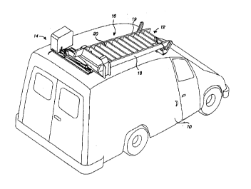
FIG. lA is a perspective view of a motorized rack system having a
stationary rack on the front roof of a service van and a motorized rack
1 0 shown in a locked-down position on the rear roof of the top of the van.
FIG. lB is a perspective view of the motorized rack system shown in a
fully-tilted, but not telescoped, po~ition on top of the van.
FIG. lC i~ a per3pective view of the motori~ed rack system shown in
a f~-slly-tilted and downwardly telescoped position for loading and unloading
of a ladder to and from the rack system on the side of the van.
FIG. 2 is a perspective view of a stationary rack.
FIG. 3 is a ~s ~eclive view of a motorized rack.
FIG. 4 is an exploded perspective ~riew of a motorized rack.
2 5 FIG. 6 i8 a perspective view of a slideable ladder carriage member
assembly.
TGR003 ~APLNIPTK 1 0
Oct-30-97 13 :01 pat king law off ice 408 685-6105 P. OZ
CA 02219696 1997-10-30
FIG. 6 i9 an exploded, perspective view of a base member assembly
and some of the component~ mounted thereto.
FIG. 7 i~ an exploded, perspective view of an elongated pivoting
member assembly.
FIG. 8 is an exploded, perspective view of some of the elements of a
ca~le control A~mbly.
FIG. 9 iB a partially exploded, perspective view of a cable control
assembly.
FIG. 10 i8 a partially sectional, top view of a cable ~pool.
FIG. 11 iB an exploded side ~riew of a cable ten~ion assembly.
FIG. 12 i8 a partially ~ectional view of a cable control asfiembly
including a motor and gear box.
2()
FI(3. 13 iB another partially sectional view of a cable control
assembly.
FIG. 14 i6 a side elevation view of a motorized rack system in a
2 5 locked-down position.
TG~003/APLN/PTK 11
Oct-30-~37 11:57 pat king law office 408 685-6105 P.0
CA 02219696 1997-10-30
FIG. 15 is a side elevation view showing the elongated pivoting
member assembly in the fully-tilt~ed, but not telescoped, po~ition.
FIG. 16 is a side elevation view showing the elongated pivoting
member assembly in the fully-tilted and downwardly telescoped position.
FIG. 17 iB a side elevation view of a m~torized cable control ~sernbly.
FIG. 18 is a plan view of a motorized rack including thc cable control
l 0 assembly.
FIG. 19 is a side elevation view of a motorized rack system with a
torsion spring in a locked-down position.
I S FIG. 20 is a ~ide elevation view of a motorized rack system with a
tor~ion spring in a fully-tilted, but not telescoped, po~ition.
FIG. 21 is an enlarged side elevation view of a motorized rack system
with a tor~ion spring in a locked-down po~ition.
FIC~. 22 is a plan view of a printed circuit controller card for a
motorized rack system.
FI(~. 23 is an electrical block diagram for a controller printed-circuit
2 5 board for a motorized rack ~y~tem.
TGR003/APLNfPTK 1 2
Cl._t-~0-~37 11:58 pat King law of 1Fice -10~ ~i85-6105 P.02
CA 02219696 1997-10-30
D~.TP.TT .~:n D~-~CRIPI ION OF T~ PE~FERREn EMBODIMENTS
Reference will now be made in detail to the preferred embodiments of
the invention, example6 of which are illustrated in the accompanying
5 drawings. While the invention will be described in conjunction with the
preferred embodiments, it will be understood that they are not intended to
limit the invention to these embodiments. On the contrary, the invention is
intended to cover alterrlatives, modifications and equivalent~, which may be
included within the spirit and ~cope of the invention as defined by the
l O appended claims.
FIGS lA, lB, and lC illustrate two principle components of a
vehicular ladder loading system according to the invention mounted on the
roof of a vehicle, such as a service van 10. One of these components is a
l ~ static, or stationary, ra~k 12 and the other component is a piYotable and
extendible ladder rack as~embly, or motorized rack 14.
FIG. lA illu~trates a typical ladder section 16 mounted in a locked-
down position on the roof of the ~an 10. The ladder 16 may be a one-piece
2 0 de~ign, as shown, an extension ladder with one or more ertenqion sections,
or a step ladder. The ladder lB includes a pair of elongated ~ide rails,
rlQ.~ ted as aIl outer side rail 18 and an irmer side rail 19, between which
extend a number of ladder rung~, typicaLLy ~hown a~ 20. It ~hould be
appreciated that other kinds of ladders or other types of elongated or bulky
2 5 equipment may al~o be u~ed with the pre3ent invention.
TGR003/APLN~PTK l 3
~JC~ ts paL~ ~ ~ng la~ ott ice 4CJ8 6~5-6105 P . 0
CA 02219696 1997-10-30
The ~tatic rack 12 i~ fi~ed to the front end of the roof of the van 10 w~th
a number of t~chni~lue~, including bolts and self-locking nuts (not shown)
and ~ i]iary mount~ng brackets (not shown) su~table for a particular ~an
or vehicle design.
s
FIG. 2 show~ the ~tatic rack 12 in more detail. The static rac3~ 12 is
typically formed as an elongated tube member 30 which is fixed to a
mounting ~h~qnnel 32. The mounting channel 32 i~ appropriately attz~ched
to the roof of a vehicle ~uch as the van 10. The tube member 30 has pair of
I O upwardly and outw~rdly e~tsn~in~ horns, or ladder guides 3~, 33 formed at
each end, as illustrated, to assist in loading and unloading of a ~adder. As
illustrated in FI~S. lA~ , the horn~ 32, 33 are each adapted to be at one
end of the ladder near a respecti~re outer or inner side rail 18, 19 of the
ladder 16. An upwardly exten~ing ladder ~tup bracket 34 is attached to the
1 5 mounting channel 30 to engage a rung of the ladder and l~e~ t the ladder
frorn sliding forw~rd or backward. A cable 3fi for securing the ladder has
one end fixed to the mo~mting channel and the oth~r end formed into a loop
for p~dlocking the ladder to the vehicle, if de~ired. A plastic boot 38 is fixedto the ladder stop bracket and pla~tic wear pads 40, 41 ~re fixed to the
O surfaces of the horns 32, 3~ and the tul}e member 30, a~ illustrated.
FIG. 3 ~how~ in perspective the pivotable and extendible lsdder ra~k
assenlbly, or motorized rack, which i~ mounted near the rear end of the
roof of the van 10. The pivotable and extendible ladder rack assembly 14
2 5 include~ a ba~e member 50, which i~ fixed ~o the roof of the vehicle 10. Thepivotable and extendible ladder rack assembly ~0 also includes an elongated
TGR003/APLNIPTK l 4
U~ ~ pat Icing ~aw oft ~ce 408 685-6105 P.04
CA 02219696 1997-10-30
pivoting member 52 which is pi~rotably mounted near the outer end of the
ba~e member 50. The elongated piYoting member ~2 has an inboard ladder
grip 54 on its inboard ~ide. The inboard ladder grip 54 is shaped to have an
upper end 56 whick is adapted to overlie the inner side rail 17 of the ladder
16.
A slideable ladder carriage member member 60 31ideably extends out
of and also retracts into the outboard end of the elongated pivoting member
52, as di~cussed a~d illu~trated in more detail herein below. At the di~tal,
or outer, end of the slideable ladder carriage member 60 is located an
outboard ladder grip 62. The outboard ladder grip 32 i~ also shaped to have
an upper end 64 which o~erlie~ the outer ~ide rail 18 of the ladder 16. When
the slideable ladder carriage member 60 i~ retracted into the elongated
pivoting member 52, the inboard and outboard ladder grips 54, 62 are
l S spaced relatively closer together to engage the respective inner and outer
side rail~ 18, 17 of ~he ladde~ in order to secure the back end of the ladder 16in position on the rear roof of the vehicle 10. As discussed herein below,
when the slide~ble ladder carriage member 60 i6 extended from the pivoting
member 52, the re~pective inboard and outboard ladder grips 54, 62 are
2 0 spaced fiurther ~part than the width of the ladder 16 to allow the back end of
the ladder to be released from or loaded onto the 61ideable ladder carriage
member 60. The ~lideable ladder carriage member 60 also has a post 66
fixed thereto for al80 preventing the l~dder from sliding forward or
backward.
TGR003/AP~N/PTK 1
~ct~ 9~ ~8 pat king law office 408 ~85-6105 P 05
CA 02219696 1997-10-30
FIGS. lA, lB, and lC also illustrate various operational positions of
an exempIary vehicuiar ladder unloading/loading system according to the
lnvention.
S FIG. l.A shows the piv~table and extendible ladder rack assembly 14
in a first locked-down, or home position in which the elongated pivoting
member 62 is horizontally positioned on the roof of the vehicle 10. In this
position, the slideable ladder carriage member 60 is retracted into the
pivotable slideable carriage member ~2 so that the inboard ladder grip 54 on
1~) the pivoting member 62 and the outboard ladder grip 62 on the ~lideable
ladder carriage member 60 both grip the rea~ end of the ladder 16 and hold
the ladder 16 iD a substantially horizontal position on the roof of the vehicle
10, as iIlu~trated. The front end of the ladder 16 horizontally rests in the
static rack 12 near the front end of the van 10, a8 illu~trated.
l S
FIG. lB show~ the pivotable and extendible ladder rack assembly 14
in a second fully-tilted, but not extended, position in which the elongated
pivo~ing member 52 i8 pivoted up at an acute angle with respect to the
generally horizontal base 50. In this position, the sliding member 60
2 0 remains retracted into the pivoting meInber 52 so that the rear end of the
ladder 16 is held between the inboard and outboard ladder grip~ 54, 62 in a
tilted position. In thi~ position, the rear end of the outer rail 18 of the ladder
16 iB slightly below the roof of the van, as illustrated. The front end of the
ladder is al~o tilted in the stationary rack 12 so that the far end of the side
2 5 rail 18 rests against the ~tatic rack 12, as iIlustrated. In this position, the
TGR003JAPLN/PTK l 6
~ct-30-97 11:59 pat king law office 408 685-6105 P.o~
CA 02219696 1997-10-30
long axis of the ladder ~6 is inclined at a small angle with respect to
horizontal, as illustrated.
FIG. lC ~hows the pivotable nnd extendible ladder rack assembly 14
5 in a third fully-tilted and extended position in which the elongated pivotiIlgmember 52 remain~ pivoted at the acute angle with respect to the base ~0
and in which the slidea~le ladder carri~ge member 60 is also telescopically
extended downwardly and outwardly from the pivoting member 52 so that
the ladder 16 rests against the outboard ladder grip 32 of the slideable
l O ladder carriage member 60. In this position, the ladder grips 54, 62 are
spaced apart more than in the first and second po~itions to permit an
operator to remove or place the ladder 1~ in or out of the ~lideable ladder
carriage member 28, a~ il]ustrated. Note that in the third position, the
outer rail 18 of the ladder 16 rests o~ the outboard ladder gTip and remains
15 at an acute angle less than ninety degrees. The acute angle allows th~
ladder 16 to clear the sid~ o~' the vehicle and also cause~ the tilted ladder toremain in the ladder carriage 28. In the third position, the rear end of the
outer rail 18 of the ladder 16 is typically positioned three or four feet above
the ground to facilitate loading and unloading of the ladder, a~ illustrated.
2 0 In this position, the long axis of the ladder 16 is inclined at a greater angle
with respect to horizontal with the side rail 18 at the fiont end of the ladder
16 resting against the static rack 12, as illustrated. The open structure
provided by the horns 32, 33 of the static rack 12 allows the front end of the
ladder 16 to pivot and remain supported by the rack.
TGR003/APLN/PTK 1 7
uct~ ~9 pat ~c i ny -i ~w c~f f i ce 408 685 - 610- P 0 7
CA 02219696 1997-10-30
As illustrated in FIG. 3 and in an exploded fo~n in FIG. 4, the
pivotable and extendible ladder rack as~embly, or motorized rack, 14
includes a base member 50 which is mounted to the rear roof of the van 10
u~ing a number of techniques, including bolts and self-locking nuts and
aw~iliary mounting bracket3 (not shown) a~r.,priate for a particular van
or vehicle design. The base member 50 is formed as an elongated
aluminum extrusion having a number of longitudinally extending T-
grooves (typically shown as 70) formed into its upper and lower sufaces.
The T-grooves are designed to hold captive the heads of mounting bolts (not
shown) for variou~ components mounted to the base member 50 and for
mounting the base member 60 to the roof of the van. The T-grooves all~w for
longitudinal adjustment of the location of the captive mounting bolt heads.
A pair cf lower pivot brackets 72, 73, each with an up~tanding ear,
l 5 are moullted to the base 50. An upper pivot bracket 74 al80 with a pair
upstanding ears is simil~rly mounted to the lower side of the ~quare
aluminum extrusion forming the elongated pivoting member 52 using T-
groove~ formed in the extru~ion. A pivot rod 76 extends through
corresponding b~l~hings in holes formed in the ears of ~he lower pivot
2 0 bracket~ 72, 73 and the upper pivot bracket 74. This arrangeme~t pivotably
mounts the elongated pivoting member 5~ near the outer end of the base
member S0.
The elongated pivoting member 52 i~ formed as a square, hollow
2 5 aiuminum extrusion with the inboard ladder grip ~4 fixed to its top ~ide
near the in~ide end. The inbo~rd l~dder grip ~4 is sn upwardly extenclin~
TGR003/APLNIPTK 1 8
~JC~-3C3~ 5~ palc k 1 ng law c~ff ice 408 685-6105 P 08
CA 02219696 1997-10-30
aluminum strap which is ~trengthened with a gusset and which has one
end fixed to the inner end of the elongated pi~oting member. The free other
end of the inboard ladder grip i9 adapted to engage with the inner side rail
of the ladder.
The slideable ladder carriage member 60 is mounted to slideably
extend from the outboard end of the elong~te1 pivoting member 26. The
slideable ladder carriage member 60 includes an inside channel member 80
which slide~ on a p~ir of ~ ble drawer ~lides 8~, 83 mounted between
] O the interior surfaces of the square aluminum extrusion 5~ and the outside
lateral surfaces of the inside ch~nnel member 80. A cantilevered ladder
carriage 84 i8 formed a~ a U-shaped channel from a sheet of aluminum
with its sides fixed to the sides of the inside C~l~nn~l 80. The outboard
ladder grip 62 i~ fixed to the distal end of the inside channel 80. The
1 5 outboard ladder grip 62 i~ also ~haped to have an end 54 which also overlie~
the outer side rail of a ladder.
FIG 5 shows details of the components of the slideable ladder
carrying member 60.
As illustrated in connection with E'I~S. 3 and 4, a cable 90 ha~ one
end attached tc the inboard end of the inside channel 80 of the slideable
ladder carriage member 60. The cable 62 passes through the pivoting
member 52, through a hole in an end cap 92 fixed to the inboard end of the
2 5 pivoting member 26, ~nd through a pulley 94 fixed to the end cap. The cable
9o al~o passes around a pulley 96 fixed tO the base 50. The weight of the
TGR003/APLN/PTK 1 9
01 pa~; K~ng law ott~ce 4U~s O~ ~lU~
CA 02219696 1997-10-30
slideable ladder carriage member 60 and the weight of a ladder extends the
slideable ladder carriage member 60 out and away from the pivoting
member 52. The ca~le 90 i9 also use~l to retract the ~lideable ladder carriage
member 60 into the pivoting member 52.
s
In the retracted position, the inside ~hP~nn~l 80 of the slideable ladder
carriage member 60 retracts partially into the elongated pivoting member
~2 so that the inboard and outboard ladder grip8 54, 62 are spaced closer
together to engage the respective side rails of the ladder to secure the rear
l 0 end of the ladder 16 in position on the rear roof of the vehic}e 10. The
slideable ladder caITiage member 60 is ~Y~n~led from the pivoting member
52 such that the respective inboard and outboard ladder grips 54, 62 can be
spaced further apart than the width of the ladder 16 to release the ladder 16
for unloading.
l 5
A pair of pne~lm~t;c struts 98, 99 are mounted on each side of t}le
base to provide a biasing force between the base member 50 and the
elongated pivoting member 52 for bi~inF the pivotable member 62 to~ard a
fully-tilted position.
As illustrated in FIGS. 3, 4, and 7, a bracket 100 with a pair of
external ears i9 mounted to the pivoting member 52. One end of each
pne~ tic ~trut is p*otably fixed to one of the ears with a ~nap-on ball ioint
connection. I'he other end is ~imilf~rly pivotably attached to respecti~e
2 5 upwardly extending ears on a locking bracket 102. A spring-loaded hooked
locking latch is also mounted to the locking bracket 102 for engagement
TGR003/APLN/PTK ~
d~ ng ~ Ot r ~ce I~D C~-C~lU~
CA 02219696 1997-10-30
with the inner end of the pivoting member 52 to lock the pivoting member 52
in a locked-down horizontal position. The ~truts 98, 99 in their compressed
or partially-compre~sed positions exert forces along their longitudinal axes.
In the fully-tilted position the elongated pivoting member 52 is pivoted at an
S acute angle with respect to the horizontally positioned base 50. The angle of
the pivoting m,ember is less than ninety degrees to allow a ladder to clear
the side of a vehicle and also to have the ladder be tilted enough ~o that it
reln~in~ in the ladder carriage 28.
1 0 With reference to FIGS. 3 and 4, the cable 90 for rai~ing and loweringthe ladder carriage has one end f;xed to the inboard end of the inside
~h~nnel, The cable pa~se~ through the pivoting member 52, through a hole
in the end cap 92 fixed to the inboard end of the pivoting member 52,
through a pulley 94 fixed to the end cap, and through the pulley 96. When
15 the pivoting member 52 is in the fully tilted position, the weight of the
slideable ladder carriage member as~embly 60 and the weight of a ladder 16
e~tend the ~lideable ladder carriage member a~embly 28 from the pivoting
member 26 as the cable i~ preci~ely spooled out by a motor. The cable 90 is
also used to retract the cli-leA~le ladder ca~iage member as~embly into the
2 0 pivoting member.
FIG. 8 shows the ~fety latch arrangement which i~ provided for
mech~r ic~lly locking the inboard end of the elongated pivoting member 52
to the base 50 when the motorized ladder rack assembly i9 in the first
2 5 locked-down, home position. The safety latch includes the spring-loaded
hook 104 which is connected to one end of a release cable 106. The release
TGR003/APLNJPTK 21
~ct-30-97 ;L3:02 pat king law off-ice 408 6~5-6105 P 05
CA 02219696 1997-10-30
cable i9 pulled to release the hook 7~. The other end of the release cable 74 isconnec~ed to a mechanically positionable control member llO.
Both the cable 90 and the release cable 106 go into a motor control unit
5 120 illu~trated in FIGS. 3, 4, 8, g, 10. ~he mechanically positionable col~trol
member 110 is spring-ioaded and mounted for rotation to a motor cover base
112. An operator control lever 114 rotates the control member 110. The
control lever 114 i9 center-positioned with springs and is rotated to pull the
cable 106 and to release the ~pring-loaded hook 104 from the inboard end of
1 0 the pivoting member 5~. A w~per 116 i~ ~tt~r~ed to the control member 110
so that, when the control member 114 is rotated to one position, the wiper
116 inteITupts a light beam in a fir~t photocell sensor 118 when the control
member is rotated to the other position; the wiper 116 interrupts another
light beam in a ~econd photocell sensor 118b. Both sen~ors 18~a, 188b are
l 5 mounted on the lower side of a printed circuit control card 120 which is
provided to control a ~ r~ible actuat~r motor 122.
The reversible DC motor 1~2 i9 connected to a gear box 124. The
actuator motor 122 and gear ~ox 124 is commercially provided, ~or example,
2 () as a United Technology Motor Sy3tem Part No. M027RM. An output eha~
of the gear box 124 i9 con~ected through a coupler 126 to a spool ~haft 128.
The ~pool ~haft 128 is rotatably mounted on bearings 130, 131 to a ~pool-and-
motor bracket mountin~ a~sembly 132. A take-up spool 134 has one end of
the cable 90 conr.ected to it by capturing a ball crimped to the end of the
2 5 cable in a keyhole slot 136 formed in the surface of the spool, as illustrated
TGR00~/APLN/PTK ~
Oct-~0-S~ 13:02 pat Icing ~aw offi~:e 408 685-6105 P 06
CA 02219696 1997-10-30
in FIG. 10. The printed circuit control card 120 is also mounted on brackets
fixed to the spool-and-motor bracket mounting bracket 132.
FIGS. 8, 9, 11, 12, and 13 illustrate a tension sensor as~embly 140
which senses reduced tension in the cable 90 and ~ qble~ the motor 122 in
response to reduced tension in the cable. Ihc tension sensor assembly 140
includes an upright frame 142 which is mounted to the motor cover base
112. A spring-loaded pivotable lever arm 144, biased at its top end by a
spring 146, is pivotably mounted to the frame 142. A roller 148 is mounted to
l O the other, lo~er end of the lever arm 144 for cont~c~ine the cable 90. A
photocell sensor 150, shown in FIG. 20, i9 mounted to the frame 142 and a
flag 1~2 at the top end of the lever arm 124 inte~Tupts a light beam in the
photocell sensor to stop the motor when the cable tension is reduced, for
example, or when the ladder carriage not moviDg for some reason.
l 5
A motor cover a~sembly 160 shown in FIGS. 4 and 9 includes a motor
cover 162, a ~ront ~ide 164, a rear side 166 which are welded together and
attached to the base 112 with appropriate fasteners. A slot 148 is provided
between the cover 142 and the ba~e 82 for the control lever 84. A slot 150 is
2 0 provided in the front side 144 for the release cable 74 for the spring-loaded
hook 72. Another slot 152 i9 provided in the front side 144 for the cable 62.
The cable 62 i8 controlled with the reversible motor 100. Tension in
the cable is sen~ed with the tension sensor assembly 120 and the motor 100
2 5 is disabled in response to reduced tension in the cable. Sensing of cable
tension include~ contacting the cable with an idler roller at one end of a
TGR003~APLN/PTK 23
Oct-30-97 13:02 pat king law off ice 408 6~85-6105 P.07
CA 02219696 1997-10-30
spring-loaded pivotable lever arm having and having a stop member at the
other end of the spring-loaded pivotable lever for interrupting the photocell
when the cable tension i~ reduced and stopping the motor.
In operation, one end of the elongated pivoting member to the base
with a safety latch in the fir~t locked-down home position using a spring-
loaded hook which i~ connected to a cable connected to a mechanically-
positioned control member. The mech~nic~lly positioned control member
is rotated to position a wiper att~rhe~ thereto to interrupt a photocell
coupled to a controller for the motor. The ~pparatus is used for ~ensing
rotation of the pulley with a shaft encoder connected to the motor, s~nAin~
the length of the cable with an integrated circuit controller which
remembers the home position (as indicated with a green led) and shutting
off the system after 30 ~econd timeouts. A relay switche~ the motor polarity
1 5 at the end of a cycle, d) an alldible signal sounds during operation.
FIGS. 14, 15 and 16 illustrate some of the steps in a method for
unloading and loading a ladder on a ~ ehicle. AB previously described in
connection with FIG. lA, the method includes engaging respecti~re side
2 0 rail~ of the ladder 16 near one end of the ladder with a static rack 12 having
a pair of upwardly e~rtent~in~ ladder ~rips.
F~G. 14 illustrates the step of holding the other end of the ladder 16 in
a first locked-down home position with the slideable carriage member
2 5 which is slideably mounted to an elongated pivoting member which is
horizontally po6itioned on top of a vehicle and which is retracted into the
TGR003/APLN/PTK 24
~ict-30~ 03 pat k i ng law off ice 408 685-6105 P 08
CA 02219696 1997-10-30
elongated pivoting member. FIG. 13 further illustrates the step of gripping
the one side of the other end of the ladder with an inboard ladder grip
mounted to the elongated pivoting member ~nd gripping the other side of
the other end of the ladder with an outboard ladder grip mounted to the
S slideable carriage member ~o that an outboard ladder grip on the distal end
of the ~litle~hle carriage member is in its closest position with respect to an
inboard ladder grip on the elongated pivoting member 80 that the ladder
grips are holding the ladder in a horizontal position on the roof of the
vehicle. The motorized ladder rack assembly i~ held in the first locked-
l 0 down position u~ing the cable 62 coupled to the one end of the pivoting
member and the cable-spoolin~ me~h~ni~m for reeling in the cable against
the bia~ing force provided by the pneumatic shock members 60, 61. In thi~
first position, the pneumatic struts 60, 61 are compressed and bias the
pivotable ~lideab]e carriage member ~6 toward l)iVO~,illE~, around the pivot pin1 5 46 at the outside end of the ba~e 24 while the cable 62 and the safety ]atch
assembly 70, when engaged, hold the inboard end of the elongated pivoting
member 26 clo~e to the base 24 in a horiwntal position.
FIG. 17 and 18 show~ a plan view of the motorized rack in the locked-
2 0 down po~ition with the pneumatic ~trut~ 60, 61 compressed.
FIG. 1~ illu~trates the ~tep of pivoting the elongated pivoting member
from the first locked-dowrl home po~ition to a second fully-tilted, but not
tele~coped, po3ition in which the elongated p*oting member i~ pivoted to
2 5 extend at an acute angle with respect to horizontal while the slideable
carriage member i~ remain~ retracted into the elongated pi~roting member
TGR0031APLN/PTK 25
~JCI.~ Y~ lJ ~ pa~ ~c ~ ny law Ot~ ~ce 40~ 685-6105 ~ ~JY
CA 02219696 1997-10-30
so that the ladder is tilted with respect to horizontal and the inboard and
outboard ladder grips remain holding the other end of the ladder. The
pivotable slideable carriage member is pivoted to the fully-tilted position
using the forces of the pneumatic struts 60, 61 as the cable 62 is paid out
S from the cable-spooling me~h~ni~m
FIG. 16 illustrates the step of extending the slideable carriage
member from the second po6ition downwardly to a third fully-tilted and
downwardly-tele~coped position in which the pivoting slideable carriage
1 () member is pushed by the extended pneumatic struts 60, 61 to remain
pivoted at an acute angle with respect to horizontal. In the third position,
the slideable carriage member 28 is extended downwardly and outwardly
from the other end of the pivoting member 26 so that the ladder grip 32 at
the first end of the pi~otable ~lideable carriage member 28 ifi in its farthest
15 position with respect to the ladder grip 30 of the sli~ling member to allow
loading or unlo~l;n~ of a ladder. The weight of the carriage member 28
and the weight of a ladder 16 are used to extend the slideable ladder
carriage member assembly 28 from the pivoting member 26 as the cable 62
i8 spooled out using the cable-spooling mech~ni~m
FIG. 22 is an electrical schematic diagram for a motorized ladder
rack assembly. FIC~. 22 shows an electrical schematic diagram which
illustrate~ the interconnections between the variou~ elements of the ~y~tem
for providing electronic control of the motorized ladder rack assembly. Note
2 5 that this preferred embodiment of an electronic control system uses no
external limit switches or sensors to control the position of the motor in
TGR0031APLN/PTK a6
Oct-30-97 13:0~ pat king law office 408 685-6105 P 10
CA 02219696 1997-10-30
order to elimin~te any malfunctions due to exposure of such external limit
switches or sensors. Most of the electrical and electronic components are
contained within the motor cover assembly.
FIG. 23 is a plan view of a controller circuit card. FIG. 23 shows the
layout of the controller circuit card, or control board 120, which is mounted
to brackets fLlced to the spool-and-motor bracket mounting assembly 132.
Termin~l~ J2 and J3 on the control board 120 are connected through
appropriate wiring to a 12 volt battery 200 to provide power to the various
electrical and electronic components. Termin~l~ J14 and J16 of control
board 120 are connected through a~Iu~riate wiring to a momentary push
button 202 which iB located within the van and operated with a key or button
to enable the electrical and electronic systems for a preset period of time.
1 5
The control board 120 and the motor 122 are located u~ithin the motor
cover a~sqmbly. Terminals J~ and J7 of the control ~oard 120 are connected
through appropriate wiring to termin~]~ of the motor 122, which is a
reversible DC motor. Termin~l~ J9 and J11 of the control board 120 are
2 0 connected through a~l~rv~riate wiring to terminPl~ of a buzzer alarm 204
which provides an audible alert signal during operation of the system.
A shaft encoder, or position sensor, 206 is mounted to the control
board 120. An input shaft 208 of the ~haflc encoder i~ connected through the
2 S ~pool shaft to the motor 100. A reversing relay 210 sets the system for
raising or lowering the ladder carriage by changing motor polarity at the
TGR003/APLN/PTK Z7
~Ict-:~0-5~ 13: 04 pat k 1 ng ~iaw of f ice 408 6~35-61~ P .
CA 02219696 1997-10-30
end of a cycle. The shaf~ encoder is used with an integrated circuit
controller 210 to sense the position ~f the ladder carriage member by
providing rotation information for the takeup ~pool 134. This rotation
information is then used to sense the length o~ the cable p~id out and,
5 hence the position of the ladder ca~age member 6~). This ~ystem a]so
remem~ers the home position. A green light-emitting diode LED 1
mounted on ihe control board 120 is lit to indicate that the system is in the
home position. A 30 seco~d timeout routine shuts off the system af~er 30
second3 of operation. A forwardlreverse function is pro ~ided by the flag 116
1 0 on the control 110 to control the direction of rotation of the motor A relay 210
switches the motor polarity at the end of a cycle.
With reference to FIGS. 22 and 23, the microprocessor 210 i~
programmed to perform various functions by receiving and storing
l S information from the position sensor encoder 206 about the ca~le being
spooled.
The mo~nentary pushbutton switch aO2 is located inside the vehicle
and no circuit breaker is utilized. The oper~tor pushes the button 202 once
2 0 to enable or arm the ladder rack electronic system to move the iadder up or
down. This button 202 als~ function3 as a system reset.
The sequence of operation is as follows The operator open~ the truck
and pushes the ~utton 202 to arm the ladder rack system. The operator has
2 5 60 second~, for example, to start using the control lever 114. If the ladder is
moved to the fully extended position, the control unit shuts itself down in
TGR003/APLNIPTK 28
Oct-30-~37 13:04 pat king law office 408 685-6105 P 12
CA 02219696 1997-10-30
five seconds. If the ladder moves to the fully retracted position and is
latched down, the control unit shuts itself down in five seconds.
Alternatively, if the control unit using the position sensor encoder 206
senses no activity of the operators control lever 114 for one minute, the
S control unit shuts itself down. The control system is reactivated by pressing
the reset button 202. If the control unit senses slack cable short of the fiully-
extended position, the unit will emit an audio alarm and prevent further
extension. The system permits retraction if the slack detector senses slack
cable. Af~cer 60 seconds, the control unit shuts down.
If the control unit is retracting or exten~lin~ and senses no movement
with the position sensor encoder 206 ~i.e., a jam), the unit emit~ an audio
alarm and prevents further retraction until the operator extends the
ladder, or pushes the button to re~et the control. unit. This requires the
operator to clear the jam condition before he can move the ladder. After 60
seconds, the control unit shuts down. Once the control unit shuts down~
the operator must push the button 202 to re-arm the ladder rack control
system. With no circuit breaker, the control unit provides overcurrent
protection for the motor by ~hutting down the system and power to the
2 0 motor upon sensing no movement. The relay 210 rever~es the polarity of the
voltage to the motor 122 to raise or lower the ladder c~rriage, deperl~ing
upon the po~ition of the control lever 114. The wiper 11B activate~ photocell
sensors 118a, 118b to raise or lower the ladder carriage.
2 5 The foregoing descriptions of specific embodiments of the present
invention have been presented for purposes of illustration and description.
TGR003/APLNIPTK 29
C~ct-30-97 13: 05 pat k ing law o~f ice 408 685-6105 P . 13
CA 02219696 1997-10-30
They are not intended to be exhaustive or to limit the in~ention to the precise
forms discloeed, and obviously many modiflcations and variations are
possible in light of the above teaching. The embodiments were chosen and
described in order to best explain the principles of the invention and its
S practical application, to thereby enable other~ ~killed in the art to best
utilize the in~rention and various embodiments with various modifications
as are ~uited to the particular us contemplated. It i~ intended that the
scope of the invention be defined by the Claims appended hereto and their
equivalents.
TGR003/APLN/PTK 30