Language selection

Search

Patent 2219897 Summary

Third-party information liability

Some of the information on this Web page has been provided by external sources. The Government of Canada is not responsible for the accuracy, reliability or currency of the information supplied by external sources. Users wishing to rely upon this information should consult directly with the source of the information. Content provided by external sources is not subject to official languages, privacy and accessibility requirements.

Claims and Abstract availability

Any discrepancies in the text and image of the Claims and Abstract are due to differing posting times. Text of the Claims and Abstract are posted:

  • At the time the application is open to public inspection;
  • At the time of issue of the patent (grant).
(12) Patent: (11) CA 2219897
(54) English Title: AN APPARATUS FOR WRAPPING FIBRE OPTIC CABLE AROUND AN OVERHEAD LINE
(54) French Title: APPAREIL SERVANT A ENROULER UN CABLE OPTIQUE AUTOUR D'UNE LIGNE AERIENNE
Status: Expired
Bibliographic Data
(51) International Patent Classification (IPC):
  • G02B 6/48 (2006.01)
  • G02B 6/44 (2006.01)
(72) Inventors :
  • BAKER, JAMES CHARLES (United Kingdom)
  • APPLEFORD, DAVID DALE (United Kingdom)
(73) Owners :
  • AFL TELECOMMUNICATIONS EUROPE LIMITED (United Kingdom)
(71) Applicants :
  • FOCAS LIMITED (United Kingdom)
(74) Agent: FETHERSTONHAUGH & CO.
(74) Associate agent:
(45) Issued: 2006-06-06
(86) PCT Filing Date: 1996-03-29
(87) Open to Public Inspection: 1996-10-17
Examination requested: 2002-03-26
Availability of licence: N/A
(25) Language of filing: English

Patent Cooperation Treaty (PCT): Yes
(86) PCT Filing Number: PCT/GB1996/000753
(87) International Publication Number: WO1996/032661
(85) National Entry: 1997-10-30

(30) Application Priority Data:
Application No. Country/Territory Date
9507492.8 United Kingdom 1995-04-11

Abstracts

English Abstract


The present invention relates to an apparatus for wrapping fibre optic cable
around an overhead line, comprising a carriage (1) which
sits on the overhead line (A) and is moveable along the overhead line (A), a
supply of fibre optic cable (B) located on one side of the
carriage (1) and a counterbalance (3) for the cable supply located on the
other side of the carriage (1). Gear means (4) are arranged to
cause rotation of the carriage (1) around the overhead line (A) when the
carriage (1) moves along the overhead line (A) thereby wrapping
the fibre optic cable (B) around the overhead line (1). Tensioning mews (5, 6,
7, 8, 9, 10, 11) are provided which apply a substantially
constant tension to the fibre optic cable (B) during all modes of operation of
the apparatus.


French Abstract

Cette invention concerne un appareil servant à enrouler un câble optique autour d'une ligne aérienne. L'appareil comprend un chariot (1) qui repose sur la ligne aérienne (A) et peut se déplacer sur cette dernière (A), une alimentation en câble optique (B) située sur un côté du chariot (1) et un contrepoids (3) associé à l'alimentation en câble optique situé de l'autre côté du chariot (1). Des dispositifs d'engrenage (4) sont disposés de manière à faire tourner le chariot (1) autour de la ligne aérienne (A) lorsque le chariot (1) se déplace sur cette dernière (A), afin d'enrouler ainsi le câble optique (B) autour de ladite ligne aérienne (1). Des dispositifs tendeurs (5, 6, 7, 8, 9, 10 ,11) sont prévus pour appliquer une tension sensiblement constante sur le câble optique (B) pendant tous les modes de fonctionnement de l'appareil.

Claims

Note: Claims are shown in the official language in which they were submitted.


-5-


CLAIMS:


1. An apparatus for wrapping fibre optic cable around
an overhead line, comprising a carriage which sits on the
overhead line and is moveable along the overhead line, a
supply of fibre optic cable located on one side of the
carriage and a counterbalance for the cable supply located
on the other side of the carriage, gear means arranged to
cause rotation of the carriage around the overhead line when
the carriage moves along the overhead line thereby wrapping
the fibre optic cable around the overhead line wherein
tensioning means is provided and arranged so as to apply a
substantially constant tension to the fibre optic cable as
the cable is wrapped around the overhead line during
operation of the apparatus.

2. An apparatus as claimed in claim 1, wherein the
tensioning means comprises a pulley arrangement around which
the fibre optic cable passes after leaving the supply and
before being wrapped onto the overhead line.

3. An apparatus as claimed in claim 2, wherein the
pulley arrangement comprises a pulley around which the cable
passes and a substantially constant biasing means acting on
the pulley wherein, as the cable is wrapped about the
overhead line, the opposing forces of the biasing means and
the tension in the cable are substantially balanced.

4. An apparatus as claimed in claim 3, wherein said
supply includes a drum carrying the cable and the pulley
arrangement includes a brake means acting on the drum which
is released after a predetermined length of cable has been
paid out.

5. An apparatus as claimed in claim 4 wherein, over a
limited backward travel of the carriage, the predetermined


-6-

length of cable is taken back under the substantially
constant cable tension.

6. An apparatus as claimed in any one of claims 1 to
3, wherein said tensioning means is operative to pull back
from the overhead line up to a predetermined length of said
optical cable under said substantially constant tension
during backward travel of the carriage.

7. Apparatus for wrapping fiber optic cable around an
overhead line comprising a carriage for running along the
overhead line, a rotary mount for a drum carrying a supply
of fiber optic cable located on one side of the carriage, a
counterbalance for the weight of the cable supply located on
the other side of the carriage, a gear drive to cause
rotation of the carriage around the overhead line when the
carriage moves forward along the overhead line whereby
optical cable from the supply is wrapped around the overhead
line, a pulley around which fiber optic cable from the
supply is folded back on itself before extending to said
overhead line, a linear guide along which the pulley is
moveable, and a tensioner which biases the position of the
pulley to maintain a substantially constant tension in the
fiber optic cable extending to the overhead line.

8. Apparatus as claimed in claim 7 further comprising
a brake to act on said drum to prevent fiber optic cable
being unwound from the drum, and a brake release operated
only on movement of said pulley along said guide against
said tensioner bias to a predetermined equilibrium position,
at which said cable can then be unwound from said drum on
continuing forward movement of said carriage.

9. Apparatus as claimed in claim 8 wherein said
equilibrium position of said pulley is a predetermined
distance from an end stop position in the direction of said


-7-

tensioner bias corresponding to a predetermined length of
fiber optic cable being wrapped around said overhead line,
whereby said substantially constant tension is maintained in
the fiber optic cable on backward movement of said carriage,
as said predetermined length of cable is pulled back from
the overhead line.


Description

Note: Descriptions are shown in the official language in which they were submitted.


CA 02219897 1997-10-30
WO 96!32661 PCTlGB96/00753
AN APPARATUS FOR WR.Ap~PING FIBRE OPTIC CABLE
AROUND AN C~PERIiEAD LINE
i
r
The present invention relates to an apparatus for
wrapping fibre optic cable around an overhead line.
The term "overhead line" is intended to be a general
reference to phase arid earth conductors of overhead
power lines and messenger cables strung between power
lines and other such lines which pass overhead.
Fibre optic cables are: now a well known and
developed art and are increasingly replacing older
forms of cabling in the fie:ld of communication.
Fibre optic cables can be employed to provide
communication links based on power distribution
networks. Conveniently, the fibre optic cable is
wound directly onto the already established overhead
line, thus utilising the neaworks which already exist
thereby linking control centres and sub-stations etc.
It is already known to use a suitable apparatus
which can move along an overhead line and
simultaneously wrap the fibre optic cable around the
overhead line. However, there is now a demand for an
apparatus which is capable of applying the fibre optic
cable to the overhead line; at a substantially
constant tension thereby ensuring that the cable
remains stable with respect: to the conductor over a
fk range of environmental conditions. In addition, the
apparatus must necessarily come to a halt upon
completing a span and while: being manhandled may even
be pushed backwards aver a limited travel. It is


CA 02219897 2005-11-04
20086-2162
- 2 -
essential under all these conditions that the applied
tension is maintained.
According to the present invention, there is
provided an apparatus for wrapping fibre optic cable around
an overhead line, comprising a carriage which sits on the
overhead line and is moveable along the overhead line, a
supply of fibre optic cable located on one side of the
carriage and a counterbalance for the cable supply located
on the other side of the carriage, gear means arranged to
cause rotation of the carriage around the overhead line when
the carriage moves along the overhead line thereby wrapping
the fibre optic cable around the overhead line wherein
tensioning means is provided and arranged so as to apply a
substantially constant tension to the fibre optic cable as
the cable is wrapped around the overhead line during
operation of the apparatus.
Also according to the present invention, there is
provided an apparatus for wrapping fiber optic cable around
an overhead line comprising a carriage for running along the
overhead line, a rotary mount for a drum carrying a supply
of fiber optic cable located on one side of the carriage, a
counterbalance for the weight of the cable supply located on
the other side of the carriage, a gear drive to cause
rotation of the carriage around the overhead line when the
carriage moves forward along the overhead line whereby
optical cable from the supply is wrapped around the overhead
line, a pulley around which fiber optic cable from the
supply is folded back on itself before extending to said
overhead line, a linear guide along which the pulley is
moveable, and a tensioner which biases the position of the
pulley to maintain a substantially constant tension in the
fiber optic cable extending to the overhead line.


CA 02219897 2005-11-04
20086-2162
- 2a -
Preferably, the tensioning means comprises a
pulley arrangement around which the fibre optic cable passes
after leaving the supply and before being wrapped onto the
overhead line.
Preferably, the pulley arrangement comprises a
pulley around which the cable passes and a substantially
constant biasing means acting on the pulley wherein, as the
cable is installed, the opposing forces of the biasing means
and the tension in the cable are substantially balanced.
Preferably, the pulley arrangement includes a
brake means acting on the drum which is released after a
predetermined length of cable has been paid out.
Preferably, over a limited backward travel of the


CA 02219897 1997-10-30
WO 96132661 PCTlGB96100753
- 3 -
carriage, the predetermined length of cable is taken
°, back under the substantially constant cable tension.
A preferred embodiment of the present invention
will now be described in detail, by way of example
only, with reference to the accompanying drawings, of
which:
Figure 1 is a perspective view of an apparatus
according to the present invention;
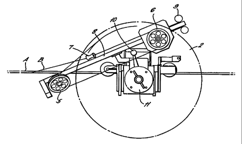
Figure 2 shows details of the tensioning means in
the apparatus in Figure 1.
In Figure 1, an apparatus is depicted for
wrapping fibre optic cable around an overhead line.
The apparatus comprises a carriage 1 which sits on the
overhead line A and is moveable along the overhead
line. On one side of the carriage 1 a supply of fibre
optic cable B is located on a drum 2. On the other
side of the carriage 1 there is a counterbalance 3 for
the drum 2 which tracks inwardly as the fibre optic
cable B is applied to the overhead line A. A gear
means 4 is also provided which causes rotation of the
carriage 1 around the overhead line A when the
carriage 1 moves along the overhead line which enables
the fibre optic cable B to be wrapped around the
overhead line A. The apparatus also includes a
tensioning means (5,6,7,8,5,10,11) which applies a
substantially constant tension to the fibre optic
cable B as it is wrapped around the overhead line A.
' 30
Figure 2 shows further details of the tensioning
means which comprises two pulleys 5 and 6 around which
the fibre optic cable B parses before entering a guide
trumpet 7 and then being applied to the overhead line
A. The fibre optic cable B is folded back on itself


CA 02219897 1997-10-30
WO 96132661 PCTIGB96/00753
- 4 -
as it is paid out from the drum 2. Pulley 6 runs on a
linear guide 8 but is restrained by a spring 9 which
ensures that tension is maintained in the fibre optic
cable B. When the carriage 1 first starts to move the
drum 2 is locked and a predetermined length of cable B
will be paid out. The tension in the cable B is
maintained at all times because the cable tension is
balanced by the substantially constant spring tension
of spring 9. When the pulley 6 nears the end of its
travel, it reaches an equilibrium position which is
the point at which it moves a lever 10 which acts to
release the drum 2. The lever 10 controls a brake 11
on drum 2 and the brake allows the drum to slip so
that cable B is paid out under tension. If the
carriage 1 should be pushed backwards, the drum 2 is
immediately locked but the cable tension is
maintained, over a limited travel, as the pulley 6
takes back the predetermined length of cable B. Thus,
the substantially constant force in the spring 9
balances the tension in the cable B, during all modes
of operation of the apparatus, as required.
With an apparatus according to the present
invention the following advantages are obtained:-
(1) A substantially constant tension can be applied
to the fibre optic cable regardless of the
quantity of cable remaining on the drum;
(2) No operator adjustment is required on site; and ,
(3) Tension in the fibre optic cable is maintained at
all times and under most foreseeable conditions
thereby greatly reducing the risk of the cable
being installed with insufficient tension.

Representative Drawing
A single figure which represents the drawing illustrating the invention.
Administrative Status

For a clearer understanding of the status of the application/patent presented on this page, the site Disclaimer , as well as the definitions for Patent , Administrative Status , Maintenance Fee  and Payment History  should be consulted.

Administrative Status

Title Date
Forecasted Issue Date 2006-06-06
(86) PCT Filing Date 1996-03-29
(87) PCT Publication Date 1996-10-17
(85) National Entry 1997-10-30
Examination Requested 2002-03-26
(45) Issued 2006-06-06
Expired 2016-03-29

Abandonment History

There is no abandonment history.

Payment History

Fee Type Anniversary Year Due Date Amount Paid Paid Date
Application Fee $300.00 1997-10-30
Maintenance Fee - Application - New Act 2 1998-03-30 $100.00 1998-01-22
Registration of a document - section 124 $100.00 1998-02-16
Maintenance Fee - Application - New Act 3 1999-03-29 $100.00 1999-01-21
Maintenance Fee - Application - New Act 4 2000-03-29 $100.00 2000-02-07
Maintenance Fee - Application - New Act 5 2001-03-29 $150.00 2000-12-27
Maintenance Fee - Application - New Act 6 2002-03-29 $150.00 2002-03-12
Request for Examination $400.00 2002-03-26
Registration of a document - section 124 $100.00 2002-08-02
Maintenance Fee - Application - New Act 7 2003-03-31 $150.00 2002-12-13
Maintenance Fee - Application - New Act 8 2004-03-29 $150.00 2003-12-15
Maintenance Fee - Application - New Act 9 2005-03-29 $200.00 2004-12-13
Maintenance Fee - Application - New Act 10 2006-03-29 $250.00 2006-03-01
Final Fee $300.00 2006-03-24
Back Payment of Fees $250.00 2007-03-01
Maintenance Fee - Patent - New Act 11 2007-03-29 $250.00 2007-03-06
Maintenance Fee - Patent - New Act 12 2008-03-31 $250.00 2008-02-29
Maintenance Fee - Patent - New Act 13 2009-03-30 $250.00 2009-03-02
Maintenance Fee - Patent - New Act 14 2010-03-29 $250.00 2010-03-02
Back Payment of Fees $250.00 2010-03-18
Maintenance Fee - Patent - New Act 15 2011-03-29 $450.00 2011-03-01
Back Payment of Fees $450.00 2011-03-23
Maintenance Fee - Patent - New Act 16 2012-03-29 $450.00 2012-02-29
Back Payment of Fees $450.00 2012-03-05
Maintenance Fee - Patent - New Act 17 2013-04-02 $450.00 2013-03-01
Back Payment of Fees $450.00 2013-03-07
Maintenance Fee - Patent - New Act 18 2014-03-31 $450.00 2014-03-07
Back Payment of Fees $450.00 2014-03-24
Maintenance Fee - Patent - New Act 19 2015-03-30 $450.00 2015-03-23
Owners on Record

Note: Records showing the ownership history in alphabetical order.

Current Owners on Record
AFL TELECOMMUNICATIONS EUROPE LIMITED
Past Owners on Record
APPLEFORD, DAVID DALE
BAKER, JAMES CHARLES
FOCAS LIMITED
Past Owners that do not appear in the "Owners on Record" listing will appear in other documentation within the application.
Documents

To view selected files, please enter reCAPTCHA code :


To view images, click a link in the Document Description column. To download the documents, select one or more checkboxes in the first column and then click the "Download Selected in PDF format (Zip Archive)" or the "Download Selected as Single PDF" button.

List of published and non-published patent-specific documents on the CPD .

If you have any difficulty accessing content, you can call the Client Service Centre at 1-866-997-1936 or send them an e-mail at CIPO Client Service Centre.


Document
Description 
Date
(yyyy-mm-dd) 
Number of pages   Size of Image (KB) 
Representative Drawing 1998-02-16 1 7
Representative Drawing 2006-05-12 1 12
Cover Page 2006-05-12 1 47
Abstract 1997-10-30 1 51
Description 1997-10-30 4 153
Claims 1997-10-30 2 47
Drawings 1997-10-30 2 26
Cover Page 1998-02-16 1 51
Claims 2005-11-04 3 101
Description 2005-11-04 5 183
Assignment 1997-10-30 4 170
PCT 1997-10-30 13 608
Correspondence 1998-02-02 1 31
Assignment 1998-02-16 6 219
Prosecution-Amendment 2002-03-26 1 51
Prosecution-Amendment 2002-05-14 1 44
Assignment 2002-08-02 4 115
Correspondence 2002-09-17 1 14
Assignment 2003-09-24 1 34
Correspondence 2003-12-29 1 20
Fees 2008-05-09 1 42
Prosecution-Amendment 2005-05-06 2 74
Correspondence 2008-04-10 1 39
Fees 2007-03-06 1 35
Fees 1999-01-21 1 41
Assignment 2004-05-07 1 26
Correspondence 2004-07-07 1 17
Prosecution-Amendment 2005-11-04 8 261
Correspondence 2006-03-24 1 38
Correspondence 2008-04-04 1 16
Correspondence 2008-05-07 1 12
Fees 2008-03-14 1 36
Correspondence 2009-03-26 1 17
Correspondence 2009-04-30 1 12
Correspondence 2009-04-09 1 41
Correspondence 2010-04-29 1 15
Correspondence 2011-04-06 1 16
Correspondence 2012-03-20 1 16
Correspondence 2013-03-14 1 15
Correspondence 2014-03-27 1 17