Language selection

Search

Patent 2219982 Summary

Third-party information liability

Some of the information on this Web page has been provided by external sources. The Government of Canada is not responsible for the accuracy, reliability or currency of the information supplied by external sources. Users wishing to rely upon this information should consult directly with the source of the information. Content provided by external sources is not subject to official languages, privacy and accessibility requirements.

Claims and Abstract availability

Any discrepancies in the text and image of the Claims and Abstract are due to differing posting times. Text of the Claims and Abstract are posted:

  • At the time the application is open to public inspection;
  • At the time of issue of the patent (grant).
(12) Patent Application: (11) CA 2219982
(54) English Title: PLASTIC LIGHT WELL WITH COVER
(54) French Title: SOUPIRAIL EN PLASTIQUE A COUVERCLE
Status: Dead
Bibliographic Data
(51) International Patent Classification (IPC):
  • E04F 17/06 (2006.01)
(72) Inventors :
  • BERGER, XAVER (Germany)
(73) Owners :
  • MEA MEISINGER STAHL UND KUNSTSTOFF GMBH (Germany)
(71) Applicants :
  • MEA MEISINGER STAHL UND KUNSTSTOFF GMBH (Germany)
(74) Agent: BORDEN LADNER GERVAIS LLP
(74) Associate agent:
(45) Issued:
(86) PCT Filing Date: 1996-05-22
(87) Open to Public Inspection: 1996-11-28
Availability of licence: N/A
(25) Language of filing: English

Patent Cooperation Treaty (PCT): Yes
(86) PCT Filing Number: PCT/EP1996/002208
(87) International Publication Number: WO1996/037671
(85) National Entry: 1997-11-24

(30) Application Priority Data:
Application No. Country/Territory Date
195 19 228.1 Germany 1995-05-24

Abstracts

English Abstract


Disclosed is a plastic light well which can be closed off with a cover (14).
The latter can be mounted in a support section (12) of the plastic light well.
To reduce load on the support section (12), a spacer element made from a
resistant material such as steel is provided between the cover (14) and the
support section (12).


French Abstract

L'invention concerne un soupirail en plastique obturable par un couvercle (14) se fixant dans une section de support (12) du soupirail. En vue de réduire la sollicitation de la section de support (12), une pièce intercalaire constituée d'un matériau résistant tel que l'acier est disposée entre le couvercle (14) et la section de support (12).

Claims

Note: Claims are shown in the official language in which they were submitted.


- 6 -

Claims
1. Plastic light well that can be covered by a cover (14, 24, 34, 44), said
cover (14, 24, 34, 44) being accommodated by a bearing section (12, 22, 32, 42) of the plastic
light well, an inset part (16, 26, 36, 46) made of a resistant material being provided between
cover (14, 24, 34, 44) and bearing section (12, 22, 32, 42) and having an L-shaped cross-section,
and one leg of said section being arranged cover (14, 24, 34, 44) and
bearing section (12, 22, 32, 42), characterized in that a holding element (47) engages at least
a part of said bearing section (12, 22, 32, 42) and said holding element (47) and one leg of
said L-shaped cross-section constitute a clamp and are clamped on a part of said bearing
section (12, 22, 32, 42).
2. Plastic light well in accordance with claim 1, characterized in that said
inset part (16, 26, 36, 46) is made of a metal material.
3. Plastic light well in accordance with claim 2, characterized in that said
inset part (16, 26, 36, 46) is made of steel.
4. Plastic light well in accordance with any of claims 1 through 3,
characterized in that said inset part (16, 26, 36,46) has an L-shaped cross-section and one leg
is arranged between cover (14, 24, 34, 44) and bearing section (12, 22, 32, 42).
5. Plastic light well in accordance with any of claims 1 through 4,
characterized in that said inset part (16, 26, 36, 46) can be secured to said plastic light well by
means of a holding element (17, 27, 37, 47).
6. Plastic light well in accordance with any of claims 1 through 5,
characterized in that said holding element (17, 27, 37) comprises a section that engages in a
region of said bearing section (12, 22, 32, 42).
7. Plastic light well in accordance with claim 6, characterized in that said
region of said bearing section (12, 22, 32, 42) constitutes a hole (18, 28, 38) or depression.
8. Plastic light well in accordance with any of claims 1 through 7,
characterized in that said holding element (27) can be bolted to said bearing section (12, 22,
32, 42).
9. Plastic light well in accordance with any of claims 1 through 8,
characterized in that said holding element (37) can be connected to said bearing section (12,
22, 32, 42) by means of a fastening peg.
10. Plastic light well in accordance with any of claims 1 through 9,
characterized in that said inset part (16, 26, 36, 46) is constructed from a plurality of pieces.


- 7 -

11. Plastic light well in accordance with any of claims 1 through 9,
characterized in that said inset part (16, 26, 36, 46) is constructed from a single piece.
12. Plastic light well in accordance with any of claims 1 through 11,
characterized in that said inset part (16,26,36,46) is provided on at least two sides of said
cover (14, 24, 34,44).
13. Plastic light well in accordance with any of claims 1 through 12,
characterized in that a plurality of inset parts (16, 26,36,46) are provided on one side of said
cover (14,24,34,44).
14. Plastic light well in accordance with any of claim 1 through 13,
characterized in that a plurality of inset parts (16, 26,36,46) are provided around the
perimeter of said cover (14, 24, 34,44).


Description

Note: Descriptions are shown in the official language in which they were submitted.


CA 02219982 1997-11-24


PLASTIC LIGHT WELL WlTH COVER
Specification:
The invcntion is a plastic light well with cover in accordance with the
preamble to claim 1.
Plastic light wells are known in a wide variety of embodiments and are
n~)nns~lly covered with a cover in order to prevent objects from falling into the light well and
in some cases in order to make it possible to walik on them. In any case, the cover should be
c~ If the light well is to be covered so that it can be walked on, the cover must of
course have an adequate load capacity. In general steel grates or steel lattices are used for
covers that can be walked on.
The covers are conventionally placed on bearing sections of the plastic light
wells. Naturally, if the cover is to withstand a certain load, i.e., if it is to be able to be walked
o~ the bearings for the covers must also with~t~n~1 this load. The light wells must be
adequately stable in the region of the bearing sections, i.e., their wall strength must be
adequate, especially in plastic light wells in which the covers are placed on bearing sections
of the plastic light well. ORen when a cover for a plastic light well is sub~ected to a heavy
load, warping occurs in the regions of the light well in which the bearing sections are
arranged; this creates a danger ofthe cover slipping offofthe bearing sections. In addition,
this causes increased wear on the bearing section~ ~e: ~ ~ when the load is removed from
the cover, the warping is relieved, so a certain relative motion occurs between cover and
bearing section when the cover is subjected to a load and then the load is removed, and this
motion leads to the plastic abrading offin the region ofthe bearing sections.
Thus, tbere are a number of ~m~nA~ placed on the plastic employed and on
the design of the bearing sections. The plastic and the bearing sections made of this plastic
should withstand the pres~e exerted, i.e., the surface p~ exerted, and the construction
should be as rigid and resistant to abrasion as possible.
Conversely, however, the plastic employed should not be too hard, because
otherwise particularly hcavily loaded sect~ons break Icldi~ely easily and also the risk of
damage ule~s during transport and h~n~li~ of the light well at the construction site. The
plastic should retain the desued properties for as long a period of time as possible, because
re~ ,in~ light wells is very eA~nsive. Since light wells are generally installed outdoors, the
plastic should not become too brittle as a result of ~A~O~ to the sun and weather.
Furthermore, manufacture of the plastic light wells should of course be as cost-efficient as
possible.
Figure S illustrates a typical plastic light well in prior art. This light well
comprises a side wall 1 that in its upper region constitutes a bearing section 2. An exterior

62329U.1112497839Cg74~8776

CA 02219982 1997-11-24

-2 -
part 5 of the cover 4 covers the bearing section 2. The cover 4 shown constitutes a gridiron
that around its perimeter comprises a metal strip that is U-shaped in cross-section and that
~ sel~s the exterior part S that lies on the bearing section 2. An edge section 3 st~ndin~
apart from the bearing section at a right angle is provided in order to hold the cover 4 in place
and prevent slippage.
Known from DE-A-25 48 256 is a plastic light well that can be covered by a
grid. In order to accommodate the grid, the plastic light well CQml~ri~S on its top side an L,
shaped profile el~m~nt suitable for a~ornmo~l~tin~ the grid Provided on the bottom side of
the grid in the ~ame region is a horizontal projecting nose that can be pushed in under the
horizontal leg of the L-shaped element in order to hold the grid on this side of the plastic light
well. A bolt connection to the L,snaped el~ is provided on the opposite side of the grid
in order to prevent accidental displ~ee~ nt of the grid that would release it from its support.
Known from DE-A-29 20 361 is a light well that can be m~n~lf~ red from
p!astic and that can be provided with ribs to stiffen it. These sti,ffening ribs can be connccted
to the actual light well via connecting means, like pegs and peg holes. A gridiron is placed to
cover the light well.
Thc objcct is achieved by the features of claim 1. The plastic light well in
accordance with the invention can be covered with a cover that is not directly accommodated
by a bearing section of the plastic light well, but rather by a special inset part that is provided
between the cover and the bearing section of the light well and that comprises
an L-shaped reinforcing section. The inset part is made of a resistant
materlal and therefore is very resistant to abrasion and can also withstand
heavy forces.
The inset part can be affixed to the plastic light well by means of a holding
elçln~nr the holding element erlg~ing at least a part of the bearing section.
Thc holding element and one leg of the L-shaped cross-section are ~1esignt~1
like a clamp so that the inset part can simply be clamped to a part of the bearing section.
The inset part distributes the load acco~ .odated so that the surface pressures
acting on the bearing section of the light well are relatively slight. The inset part furthermore
stiffens the plastic light well. A very resistant and long-lived bearing is created for the cover
by means of the inset part. 'rhis rrlakes it possible to design the plastic light well much more
simply and to use a plastic that is cost-efficient and easy to process.
This is how it is possible to m~nuf~ot Ire a co~ rely cost-efficient plastic
light well that can still with~t~nc1 heavy loads.
Another advantage of the light well in accordance with the invention is that
the final height of the cover can be varied simply by using inset parts of differing thickness.
Different covers having different thickness are often available for a particular plastic light
well, so that different final heights result depending on the cover used; this is undesirable.
This situation can be remedied in the light well in accordance v~ith the invention by inset
pieces having different thicknesses.

- - - - - -
CA 02219982 1997-11-24
.


The inset part is preferably made of a metal, e g, steel. This type of inset
piece is easy and cheap to m~nllfAr,tl~re and is very resistant. The inset part can be galvanized
or made of stainless steel in order to protect it against rust.
Since the cover when in place must generally also be secured against slippage,
conventional light wells comprise an edge section that projects at a right angle to the bearing
section and thereby prevents the cover from slipping. Because of the L-shaped design of this
inset part the edge section can be omitted and the in~t part can assume its function, this
further sirnplifying the design and m~nllfActllre of the plastic light well.
Of course it is sufficient if a section of the inset part comprises an L-shaped
cross-section, so the entire inset part does not have to be L~shaped. The ~shaped cross-
section furthermore has the advantage that the height of the edge section can be varied sitnply
by means of different inset parts and thus can also be adapted to the cover used in order to
make nush the covcr and edge section surrounding the cover.

The inset part can comprise a holding element that is ~ t to an interior
edge of the light well so that the inset part is secured against outward fii~pl~ ment
The inset paTt can also compriC~ a section that engages in a region of the
bearing section, e.g., a hole or depression.
The inset part can comprise a single piece or multiple pieces. The inset part
should be provided on at least two sides of the cover in order to ensure that the cover is
securely situated. There can of course be multiple inset parts on one side of the cover.
Multiple inset parts can be provided around the perirneter of the cover.
However, one inset part can also be provided on each of two opposing sides of the cover,
each inset part eytont~ the entire length of the side. One or more inset parts can also be
provided such that the cover is situated around its entire perimeter of one or multiple inset
parts.
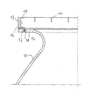
Figure 1 is a sectional view of a first exemplary embodirnent of a plastic lightwell with cover in accordance with the invention.
Figure 2 is a sectional view of a second exemplary embodiment of a plastic
light well with cover in accordance wi~ the invention.


6~32984.1~12497g39C9~418776

CA 02219982 1997-11-24


-4-
Figure 3 is a sectional view of a third eY~-mr-l-qry embodiment of a plastic light
well with cover in accordance with the invention.
Figure 4 is a sectional view of a fourth e~mrl~ty embodiment of a plastic
light well with cover in accordance with the invention.
- Figure S is a sectional view of a prior art plastic light well with cover.
Figure 1 illustrates a first eY~tnrlqry embodiment of the invention. A side
wall 11 ofthe plastic light well tr~n~iti- ns in its upper region into a bearing section 12 that
al>~n~xi...~t~ly in its center is provided a hole 18. The exterior part 15 ofthe cover 14 does
not rest directly on the bearing section 12, but rather rests on an inset part 16 that is provided
between bearing section 12 a nd cover 14. Ihe inset part 16 Cc)~ n;ses an e.ss~ns~ yL
shaped cross-section, a hon7nns~11y sjtu~te~ leg being arranged ~t~ cover 14 andbearing section 12 and the other leg being vertically onPnt~ and con~ g an edge section
13 that prevents the cover 14 from slipping and thus secures it against sidewards motion.
In order to fix it securely at the bearing section, the inset part 16 is provided a
holding element 17 that extends in a d~ direction &om the ho.i~o~llally situated leg
and is accommodated in the hole 18 ofthe bearing section 12. The i11ustration is merely a
drawing that sketches only the most important features of the invention. In practice the
diameter of the hole 18 will be smaller in order to keep to a minimutn the play of the inset
part 16 relative to the bearing section 12.
Figure 2 illustrates another exemplary embodiment. In this emho~limPnt, the
side wall 21 transitions into a bearing section 22 that is likewise provided with a hole 28.
However, in this exemplary embodiment the inset part 26 is bolted to the bearing section 22.
The eY~-mrl~ry embodiment illustrated in Figure 2 can also be used with inset parts that are
positioned in the hole of the bearing section in accordance with Figure 1 simply by means of
a holding el~ m~nt, however.
In the illustrated exemplary embo-limPnt the inset part 26 likewise is provided
an L-shaped cross-section, the ho.,~oll~lly situated leg that is arranged ~~ cover 24 and
bearing section 22 simultaneously con~ a holding element 27. The leg is provided a
conical bore in which the head of a flat-head bolt 29 can be ac~.~ t~ flush. The bolt
29 is inserted through this bore and the hole 28 of the bearing section 22 and is secured on
the other side of the beanng section 22 by means of a nut 30. This is how ~e inset part 26
can be securely and very reliably co--nt~cle~l to the bearing section 22 of the plastic light well.
In the third exemplary embodiment in accordance with Figure 3, the I,shaped
inset part 33 is provided, at the leg alTanged between cover 34 and bearing section 32 of the
side wall 31, a f:~tentng peg 37 that is welded on and that engages in a hole 38 of the bearing
section 32.


62329U 1112497839C97~18776

CA 02219982 1997-11-24


All of the ~mho~imPntc descnbed thus far have a hole in the bearing section~
This means that the v~idest variety of inset parts can be employed as desired in these
embo~lim.ontc The exemplary embodiment described next does not have a hole in the
bearing section, so the costs of mqmlfqrtllring the plastic light well can be reduced even
further. In this exemplary embodiment the inset part is secured to the bearing section by
nring Natura~ly ap~ te inset parts can also be ~;ed on bearing sections that areprovided a hole or depression
The inset part 46 in this e~cempl~ly embo~lim~nt comprises t~tvo parts
c~nnecte~l to each other, each having an L-shaped cross-section and co...~ d to each other
in such a way that the ver~cal legs are ;~diM~nt to each other and the h~ legs are a
certain fiiC~nee fi~m each other. Naturally this inset pan 46 can also co~ J~ a single
piece. Ibe di-t~ ~h. _e~ the ~~ r~ l le~s is such that it is less than the thic~ ss of the
bearing section 42 at least at one loc~on The lowcr leg, which fimctions as holding elem-~nt
47, is provided an end 50 that is bent duw~ in oIde~ to facilitate pl~etl~ent of the inset
part 46 on the bearing section 42.
l~e inset part 46 is simply placed on the bearing section 42 so that the lower
leg is situated under the bearing sectiorl 42, the upper leg ~)eing situated over the bearing
section 42 so that afler the cover is placed upop it, the upper leg is ~ngecl b,.,l~.~en t~he
covcr and the bearing section 42. Ttlis is how t~e bearillg section 42 is protected against
excessive stress from ~e cover 24,


6232984.1112497839c97418776

Representative Drawing
A single figure which represents the drawing illustrating the invention.
Administrative Status

For a clearer understanding of the status of the application/patent presented on this page, the site Disclaimer , as well as the definitions for Patent , Administrative Status , Maintenance Fee  and Payment History  should be consulted.

Administrative Status

Title Date
Forecasted Issue Date Unavailable
(86) PCT Filing Date 1996-05-22
(87) PCT Publication Date 1996-11-28
(85) National Entry 1997-11-24
Dead Application 2001-05-22

Abandonment History

Abandonment Date Reason Reinstatement Date
2000-05-23 FAILURE TO PAY APPLICATION MAINTENANCE FEE

Payment History

Fee Type Anniversary Year Due Date Amount Paid Paid Date
Registration of a document - section 124 $100.00 1997-11-24
Application Fee $300.00 1997-11-24
Maintenance Fee - Application - New Act 2 1998-05-22 $100.00 1998-04-23
Maintenance Fee - Application - New Act 3 1999-05-24 $100.00 1999-02-26
Owners on Record

Note: Records showing the ownership history in alphabetical order.

Current Owners on Record
MEA MEISINGER STAHL UND KUNSTSTOFF GMBH
Past Owners on Record
BERGER, XAVER
Past Owners that do not appear in the "Owners on Record" listing will appear in other documentation within the application.
Documents

To view selected files, please enter reCAPTCHA code :


To view images, click a link in the Document Description column. To download the documents, select one or more checkboxes in the first column and then click the "Download Selected in PDF format (Zip Archive)" or the "Download Selected as Single PDF" button.

List of published and non-published patent-specific documents on the CPD .

If you have any difficulty accessing content, you can call the Client Service Centre at 1-866-997-1936 or send them an e-mail at CIPO Client Service Centre.


Document
Description 
Date
(yyyy-mm-dd) 
Number of pages   Size of Image (KB) 
Abstract 1997-11-24 1 9
Description 1997-11-24 5 282
Claims 1997-11-24 2 69
Drawings 1997-11-24 5 47
Cover Page 1998-03-16 1 29
Representative Drawing 1998-03-16 1 4
Assignment 1997-11-24 3 125
Correspondence 1998-01-30 1 29
Assignment 1998-03-19 2 56
PCT 1998-01-23 5 143
International Preliminary Examination Report 1997-11-24 12 425