Note: Descriptions are shown in the official language in which they were submitted.
CA 02220039 1997-10-31
WO 96135577 PCT~JS9~ '0~,909
RADIALLY EXPANDABLE VASCULAR GR~FT WITH RESISTANCE TO
LONGlIVD~AL COMPRESSION AND METHOD OF MA~ING SAME
Back~round of th,~ Tnvention
The present invention relates generally to radially çxr~n-1~hle tubular grafts which are
to longihl-lin~l c~ lession resnlting from an axially applied extern~l force, and is
resistant to axial shrinkage or axial foreshortening upon radial expansion. More particularly,
the present invention relates to a microporous polyl~ nuoroethylene (~PTFE") endovascular
graft which has a leil~leillg structure integral with or bound to the graft which permits radial
expansion of the graft and stabilizes the graft against axial shrinkage upon radial expansion of
the graft. P~ e to axial shrinkage is particularly desirable where a vascular graft is
moun~ted onto a radially e~ hle endoluminal stent or alone onto an expansion balloon for
intr~lnmin~l delivery and radial exr~n~ion.
The term "longit~ in~l coll,~l~ssion~ means a reduction in a lon~ihl~lin~l dimension
resull:ing from an axially applied e~t~n~l force.
Radially expandable stents are used to m~int~in an occluded ~n~tomi~al passageway in
an unoccluded state. For example, the use of radially exr~n~l~ble stents in endovascular
applications is well known, as exemplified by U.S. Patents 4,733,665, 4,739,762, 4,776,337,
4,793,348 relating to balloon expandable endoluminal stents, all issued to Palmaz, et al., U.S.
Patents 4,580,568, 4,800,882, 4,907,336, 5,035,706, 5041,126, 5,282,824 relating to balloon
expandable and self-exr~n~ling endoluminal stents, all issued to Gianturco, et al., all of which
are hereby incorporated by reference for the purpose of exemplifying stent types useful with
the longit~ in~lly rei~ ced grafts of the present invention.
The use of radially expansible stents is not, however, limited to endovascular
applications. Rather, various types of endolnminal stents are also employed to m~int~in other
CA 02220039 1997-10-31
W 096/35577 PCTrUS~C/OS~0
alla~o~ical passageways, such as biliary ducts and ureters in an un~crhldecl condition. In those
uses where it may be desirable to cover the stent with a biocomp~tible material, particularly
one which will promote tissue ingrowth, such as PTFE, the stent is covered with the
biocomr~ihle material. In ~e endovascular i~Le~vel~lional ml~rlir~l field, endovascular stents
may be covered by co-axially disposing a tubular PTFE vascular graft over an endovascular
stent, the stent-graft assembly is introduced endovascularly and delivered to the desired
location, whereupon the stent-graft assembly is radially e~r~n~1~A, such as by balloon ~ t~ltic)n
to secure the stent-graft assembly against the vessel walls.
Balloon exr~n~ion of the stent-graft assembly occurs at p.es~ ,s sufficient to cause
both the stent and the graft to radially exp~n-l As used herein, the terms ~axial shrinkage"
and "axial foresho~ ," are used illLel~-h,...~ hly to describe a reA~lcti-)n in the longihl-lin~l
length of the graft alone or the graft relative to the lon~h~ in~l length of the stent which occurs
upon radial exp~n~iQn of the graft or the graft-stent cullll)"~ion. Axial shrinlcage of the graft
relative to the associated stent typically results in exposure of the proximal and/or distal end
of the stent. Such exposure may, in hlrn, provide a fluid passageway for body fluids, such as
blood, to flow between the abluminal wall of the graft and the lllmin~l wall of the anatomical
passageway, e.g., a blood vessel. Such an escaping flow as in, for example, an arterio-venous
fistula repair, is undesirable and may be associated with increased mortality and decreased
patency of the graft or stent-graft. It is desirable, therefore, to provide a tubular PTFE
struchure which is lesi~ to axial shrinkage during radial expansion of the PTFE structure.
_
CA 02220039 1997-10-31
W 096/35577 PCTrUS96105909
R~ tl of the Prior Art
The use of co~ting.c, wraps and impregnated materials in co,ljul";Lion with PTFEvascular grafts is known. However, in the prior art, such coatings, wraps or impregnated
materials are used for example, to I) increase the tear strength of the PTFE (Mano et al, U.S.
Patent No. 4,306,318); ii) enh~nre endothelialization of the PTFE; iii) enh~nre mechanical
compliance of the PTFE (Gogolewski, U.S. Patent No. 4,834,747); iv) seal the microporous
network present in exr~n~le~l PTFE (Flecl~e.,~l~hl, et al, U.S. Patent No. 4,902,290), v)
increase radial and longihl-1in~l elasticity of the PTFE graft (Tu, et al, U.S. Patent No.
~,061,276); vi) provide a self-sealing component to the PTFE graft to seal suture holes or
needle punctures (Mano, U.S. Patent No. 4,304,010); or vii) provide binding sites for
ph~rm~ologically active agents (Greco, et al, U.S. Patent No. 4,749,585; Mano, U.S. Patent
No. 4,229,838).
To date, however, the prior art is devoid of an tubular PTFE structure having means
associated therewith to impart a le~ ce to longitll~lin~l co~ ession or axial shrinkage upon
radial exr~n~ion of the tubular PTFE structure. The present invention offers a solution to this
defic:iency in the prior art.
Sllmm~T~ of the Inventio~
It is an object of the present invention to provide a means for structurally leillfolcillg
a tubular PTFE structure to impart resistance to longitll~lin~l c~ lplession or axial shrinkage
which occurs during radial expansion of the tubular PTFE structure.
CA 02220039 1997-10-31
W O 96/35577 PCTrU3g6/05~0
It is a further object of the present invention to provide at least one ~ lly
longitl~in~lly non-compressible, longihl-lin~lly non-compliant structure ~ ri~ g integrally
bound and axially po~itio~ along a lon~it l-iin~l axis of the tubular structure PTFE.
It is a still further object of the present invention to provide at least one lcillçolcillg
structure integrally bound and axially positioned along the longit l~in~l length of the tubular
PTFE structure on at least one of a luminal wall surface, an abluminal wall surface or residing
within the wall of the tubular PTFE structure.
It is yet a further object of the present invention to provide at least one ~ olcillg
structure made of a biocomratihle melt thermoplastic which is integrally bound to the
microporous matrix used to make the vascular graft.
It is a still further object of the present invention to provide at least one lCillL;~ g
structure made of a melt thermoplastic having a melt viscosity sllffiripnt to pelleLl~te the
microporous matrix of çxr~n(1e~1 polytetrafluoroethylene.
It is a still further object of the present invention to provide a l~.,~l~;illg structure made
of a solvent borne, thermoplastic or photo-curable plastic capable of integrating into interstices
in exran-le~l polytetrafluoroethylene.
It is yet another object of the present invention to provide a lcl-~rcillg structure made
of plastic materials selected from the group co~ ting of polyamides, polyimides, polyesters,
poly~l~ylenes, polyethylenes, polyfluoroethylenes, polyvinyl~yl~lidones, fluorinated
polyolefins such as fluorinated ethylene/propylene copolymers ("FEP") such as tetrafluoro-
ethylene/hexafluloplo~ylene copolymer, perfluoroalkoxy fluorocalbolls ("PFA") such as
tetrafluoro-ethyl/perfluoro propyl vinyl ether copolymer, ethylene/tetrafluoroethylene
copolymers ("ETFE"),polyvulyl~yll~lidone(~PVP") or similar bioc~mp~tihle plastics which
are capable of being bound to e~cr~n-1~1PTFE at tempeldL~Ires below the sintering ltlll~ldLulc
CA 02220039 1997-10-31
WO 96135577 PCT/IJS9SJO_91)~
of PTFE of at least 327~C, such as by cross-linking in the presence of cross-linking agents or
mech:~nir~l bonding by application of ples~ul'e to cause the thermoplastic to flow into the
microporous structure of the exran~ 1 PTFE substrate.
It is a still further object of the present invention to provide an aqueous dispersion of
a leill~l.;ulg m~t~ri~l which is coated onto an ~xr~n-led PTFE tubular structure. After coating
and drying the lCUlr~ ;illg m~t~ri~l onto the exran~led PTFE tubular ~Llu~;lulc the fe;llrol~ g
material imparts lesi~ e to longibl-lin~l co~ ion or axial shrinkage upon radiale~r~n~ion of the tubular PTFE structure.
It is yet a further object of the present invention to provide an aqueous dispersion of
polytetrafluoroethylene in surfactant, such as polyLeLldfluoroethylene octyphenoxy-
polyetho~y~;ll~ol, as a coating mto~ m for coating the dispersion onto an expanded PTFE~
tubuLIr structure.
It a still further object of the present invention to provide a structural reinforcement
member made of a bio-comr~tihle metal or plastic, either co-extruded with or integral with the
tubular PTFE structure, to impart resi~t~nee to lon~it~ in~l cc,.~res~ion or axial shrinkage
which occurs during radial expansion of the tubular PTFE structure
Another object of the present invention is to provide an a~?~dlus for m~mlf~etllring the
longinl-lin~lly non-compliant PTFE tubular structure and a method of m~mlf~etllre thereof,
employing a tubular mandrel for canrying the tubular PTFE structure, the mandrel having a
plurality of openings passing through the tubular mandrel and co~n~ tinE between a
mandrel lumen and an outer surface of the mandrel, a generally cylindrical mold having a
plurality of longihl~lin~l grooves, whereby the exr~nr1Pd PTFE tubular structure is mounted
onto the mandrel, the generally cylindrical mold is then concentrically disposed about the
tubular PTFE structure and mandrel, there being tight tolerances between the components of
CA 02220039 1997-10-31
W 096/35577 PCTrUS96/05909
the assembly. A melt thermoplastic, such as FEP, is injected into and through the longihl~in~l
grooves in the mold, and a vacuum is applied through the lumen of the mandrel. The vacuum
acts on the melt thermoplastic through the openings in the mandrel and the microporous matrix
of the exp~n~le<~ PTFE to draw the melt thermoplastic into the microporous matrix of the
expanded PTFE. After cooling the assembly, the assembly is tli~eng~ed, and the reslllting
hubular PTFE structure has a plurality of substantially non-compliant longihl~lin~lly oriented
~c~lrOlCu~g ~Llu~;LulcS made of the melt thermoplastic integrated with the microporous matrix
of the PTFE hlbular struchure.
These and other objects, r~,aLu.cs and advantages of the present invention will become
more a~cllL to those skilled in the art when taken with refercuce to the following more
detailed description of the pl~,rcl~cd embo(~ of the invention in conjull~;Lion with the
accc,..l~lyiulg drawings.
Brief Description of the Drawin~
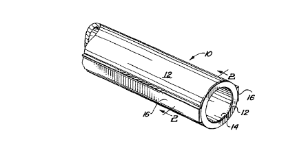
Figure 1 is a perspective view of a vascular graft having a r~iu~.ciu.~ structure to resist
axial shrinkage during radial expansion.
Figure 2 is a cross-section~l view taken along line 2-2 of Figure 1.
Figure 3 is a diag.,.."",~tir elevational view of a second embodiment of the present
invention illustrating application of a solvent-borne lch~c~lciulg structure to a vascular graft.
Figure 4 is a diagl~""-~tic end elevational view of the second embodiment of thepresent invention illustrating application of a solvent-borne lch~rolcillg structure to a vascular
graft.
Figure 5A is a perspective view of a third embodiment of the present invention
illustrating a plurality of reinforcing rib structures associated with a tubular vascular graft.
CA 02220039 1997-10-31
W 096/35577 PCTrUS96105909
Figure 5B is a cross-sectional view taken along line 5B-5B of Figure 5A.
Figure 6 is partially exploded dia~-,...,."i1~;r view of the present invention illnstr~ting
the method for applying an integral i~:ulrvl~ g structure to a tubular vascular graft.
Figure 7 is a partial cross-sectional view illu~ a~illg a mandrel and a mold used to apply
S an integral ~ rOlcillg structure to a tubular graft in accordallce with the method of lhe present
invenl:ion.
Figure 8 is a cross-sectional view taken along line 8-8 of Figure 7, illustrating a
mandrel, mold and vascular graft assembly in accordance with the method of the present
invem:lon.
Figure 9 is a cross-sectional end-elevational view illustrating a second embodirnent of
the m,andrel, mold and vascular graft assembly in accordance with the present invention.
D~.t~iled Desc~i~lion of the PlC~r~ d Fmho~iime~tc
Turning now to Figures 1-2, there is illustrated a first ~l~Ç~ d embodiment of avascular graft 10 with structural means 16 for imparting the graft 10 with resi.ct~nre to
lon~ in~l co~ es~.ion or axial shrinkage operably associated with a tubular graft member
12. Tubular graft mPmhe.r 12 has an outer wall surface 13 and a central lumen 14 defining an
inner lnmin~l surface 15. Structural means 16 consists generally of a lei~c,lchlg member
which. is co-extruded with, bonded to or integral with either the outer wall surface 13 or the
luminal wall surface 15. Where the ~.Llu~;Lulal means 16 is bonded to the graft 10, bonding may
be accomplished by a variety of bonding methods. For example, a bond may be created by
mech:~nic~l means, such as applying positive or negative pressure which causes physical
interaction between the structural means 16 and the microporous matrix of the graft member
12. M;ech~nic~l bonding may be accomplished by application by use of melt thermoplastics as
CA 02220039 1997-10-31
W 096/35577 PCTrUS96105909
the structural means 16, caused to flow under the influence of a heat source, such as
ultr~ound, resistive heating, l~er irr,~ tion, etc. ~llr~ iv~ly, the ~Llu~;lulal means 16 may
be çh~mir~lly bound, such as by cross-linking agents or bioco...r.~ le adhesives, to the tubular
graft member 12 during m,lm~f~t~lre.
S The ~tlu~;luldl means 16 may further consist of a l~ illrulcillg region 19 formed within
the graft ..~ 12 wall thir~n~os~ between the ]~lminAl surface 15 and the outer wall surface
13 of the tubular graft member 12. The method used to form the ~eulroleulg member 16 or
the reiurolci-lg region 19 will be more fully described helei.lar~r with lcfe.cllce to the best
mode ~lcsellLly known to the UlvenlOls hereof.
In accol~lce with the yl~r~l~cd embodiment of the present invention, the tubular graft
member 12 is made of microporous ~r~n~ poly~t;L.dnuoroethylene (e-PTFE). The method
of making microporous e-PTFE plc,~llleses by paste extrusion and exr~n~iQn of the extrudate
is well known in the art. Miclu~ul~us e-PTFE is comprised of characteristic nodes and fibrils
interconnPcting the nodes. Interstices between the nodes and fibrils form pores which exist
throughout the material matrix of the e-PTFE. E-PTFE vascular grafts have met with
considerable acce~Lallce due, in large part, to their bioc~ )ility and suscey~ibility to tissue
ingrowth into the microporous material matrix.
Tubular vascular grafts made of e-PTFE are well suited for endolllmin~l use. A
~lill~;i~al difficult associated with en~ lllmin~l grafts lies in the means used to attach or anchor
the endoluminal graft to elimin~te displacement of the graft due to body movements or fluid
flow through the anatomical passageway in which the graft is placed, e.g., a blood vessel. As
exemplified by Barone, et al, U.S. Patent No. 5,360,443, issued November 1, 1994, which is
hereby incorporated by reference, endovascular stents have been used as an anchoring
m~ch~ni~m when sutured to a graft, endovaccnl~rly delivered and radially exr~n~led to exclude
CA 02220039 1997-10-31
W O 96135'-.77 PCTrUS9C/0~90~
an abdominal aortic aneurysm. In Barone, stent is provided at proximal and distal ends of a
graft a]ld is sutured thereto, such that a lon~itll~in~l section of the stent is UllcO~ d to provide
direct contact between the stent and the intima. The entire assembly is delivered using a
deliveIy c~thPter and exp~n~l~hle balloon. Upon positioning of the stent in the desired
endovascular position, the exran~l~hle balloon is ~l~,S~7Ule ~ t~te~l. The radially e~al~.iv~;
force from the e~ a~ g balloon impinges upon the endovascular stent and causes the stent
to radially expand into contact with a luminal surface of the graft and the intimal surface of the
V~Cll~ re.
When used as a covering for an endovascular stent, an e-PTFE vascular graft is radially
expanded contemporaneously with the expan~ion of the endovascular stent. One particular
fliffis~lllty associated with balloon expansion of a stent-graft assembly is that the balloon will
typica]ly assume an bulbous configuration at each of its proximal and distal ends. Balloon
exr~n~ion typically forces the graft or the stent-graft assembly into a torroidal shape with the
proximal and distal ends flaring away from the central axis of the stent-graft assembly wi~ a
relatively narrow center section interm~ te the flared distal and ~lo~ lal ends. This
phenomenon occurs because there is little resi~t~nre to inflation at each of the proximal and
distal ends of the balloon relative to the balloon area covered by the stent-graft assembly. The
e~p~n~io~ balloon thus a~sllm~s a "dog-bone" configuration with the proximal and distal ends
radially exp~n-ling to a greater extent tnat a central region along the longit~-(1in~1 axis of the
stent-graft or graft. The infl~tion ~ S~.ule within the balloon exerts an radially ~a~ e force
against the balloon along its entire longitll-lin~l axis. However, because the device to be
expanded, i.e., a stent-graft assembly or a graft, restrains against radial expansion, the
expansion ~l~s~.ules within the balloon act first on the proximal and distal ends which are un-
restrai]led by the device to be e~cp~ntle(l, thereby causing the ~,o~iulal and distal ends to inflate
CA 02220039 1997-10-31
W O 96135577 PCTrUS9G~05~G~
first, causing the dog-boning effect. The rçsnlting effect is that the graft or the stent-graft
assembly is non-uLuÇol.llly radially expanded along its lon~ih~in~l axis.
A ~.hl~i~al difficulty with stent-graft assemblies, i.e., those in which an endolnmin~l
stent is covered or lined with a graft, lies in the axial foresho-~ ."lg of the graft relative to the
stent upon radial exp~n~i~ n of the stent-graft assembly. Where either a proximal or distal end
of the stent is exposed, there is a great probability that the stent will allow body fluids, such
as blood in the vascular system or bile in where the stent-graft is employed in a biliary duct,
to ci.~;u,..ve-l~ the stent-graft assembly c~llsing an undesirable leak. Thus, there is an
appreciable danger of increased mortality or morbidity where a graft covering longitll~lin~lly
foreshortens relative to the stent during radial expansion of the stent-graft assembly.
Axial foreshortening of a radially e~r~n-l.ocl graft complicates endolnmin~l graft or
stent-graft delivery. As the graft is radially exr~ntle~l and longibl(1in~lly foreshortens, there
is a b-lnrhing phenomenon which occurs. The b.~"rl~ g phe..o.lle--on results in a greater
density of graft material per area of surface are of the expansion balloon. The result of graft
material bnnrhing is to increase expansion p.es~u.es required to radially expand the graft or
stent-graft assembly to the same (li~mPtrr over a non-longibl(lin~lly foreshortened graft.
To guard against undesirable axial foreshortening of the graft upon radial e~cr~n~ n,
the inventive l~h~-~;ed graft member 12 has at least one ~,hlrulcil~g structural support means
16 operably associated therewith. The ~ei"r~ l-g ~Llu~;luldl support means 16 may consist of
alternative .eh~-~;iu-g structures bonded to, co-extruded with or integrally incorporated within
the graft member 12. In accordance with alLel.laLi~/e ~leÇ~ d embo~limrnt~ of the present
invention, the rehlfclcillg structural support means 16 is either molded onto a tubular graft
member 12 or coated onto tubular graft member 12 by application of a dispersion solution,
either in aqueous or colloidal form.
CA 02220039 1997-10-31
W 096/35577 PCTrUS9C/OJ~09
Regardless of the manner in which the le~rorcu~g structural sup~o.~ means 16 is
produced in association with the tubular graft member 12, the reil~lcilly, structural ,u~po~L
means 16 will impart resict~n~e to longi~ in~l colll~l~ssion and axial foreshortening of the
tubular graft member 12. The plOp~y of l.,.~i!iL~ e to lon~ in~l colll~ ssion and axial
S foresho.l~ g exists irrespective of the force or impetus which causes the lon~ in~l
cc,lll~l, ssion or shrinkage. Thus, the property of resict~n~e to longihl(lin~l colll~lession and
axial foreshortening will restrain the tubular graft member 12 during radial exp~ncion of the
tubular graft member 12, during application of an externally col..~.~ssive force, or will operate
against recoil properties of the e-PTFE material.
As illustrated in Figures 1 and 2, the ~ rolc~llg structural support means 16 is either
applied to the outer 13 or inner 11 wall surface of the tubular graft m~mh~r 12 or inc(3-~-J-d~d
as an integral rei lrorcillg region 19 of the material matrix forming the tubular graft member
12. ln accordance with this first ~l~Ç~..ed embodiment of the reinro.ced vascular graft 10,
the reinroicillg structural support means 16 is formed of a biocompatible longihl~lin~lly
inc~ p.e3sible plastic rnaterial, such as a melt thermoplastic selected from the group concicting
of polyamides, polyimides, polyesters, poly~lo~ylenes, polyethylenes, polyfluoroethylenes,
polytetrafluoroethylenes, polyvinylpyrolidones, fluorinated polyolefm3 such as fluorinated
ethylene/propylene copolymers ("FEP") such as tetrafluorethylene/h~Y~ .. o~ ylene
copolymer, perfluoroaLkoxy fluorocarbons ("PFA") such as tetrafluoroethyl/perfluoro propyl
vinyl ether copolymer, ethylene/tetrafluoroethylene copolymers ("ETFE") or similar
biocompatible plastics which are capable of being integrally bound to e~pan~le~l PTFE.
r~ ively~ the reinforcing structural support means 16 may be formed of a curable plastic
materiial, such as polyv",yl~yllolidone, which is curable upon exposure to thermal energy,
such as application of laser irradiation, or upon exposure to light, such as a W curable
11
CA 02220039 1997-10-31
W O 96135577 PCTrUS96/05909
"late,ial. ~llr~ iv~ly, the leillforcing structural support means 16 may be formed of a
biological tissue, such as collagen, which is capable of being cured by cross-linking agents into
a s~lkst~nti~lly monolithic structure bonded or integral with the e-PTFE tubular graft material
12.
The rehlro,~ structural support means 16 may also consist of a m~.t~llic wire co-
extruded with the e-PTFE tubular graft material 12 and po~itit n~l within the wall thif kn~ss
of the e-PTFE tubular graft material 12. Al~ dliv~ly, the m~t~llir~ wire structural member
is capable of being co-extruded with plastic beading, such as non-exp~n-l~od PTFE, as is known
in the wire-making arts where PTFE is employed as an electric~l in~ ting covering for
electrical wires, and the co-extruded metal-PTFE beading then mech~nir~lly or cht~mically
bonded to the outer 13 or inner 11 wall surface of the e-PTFE tubular graft material 12.
Those skilled in the art will a~plecid~ that a myriad of biocol,~aLible materials exist
which may be molded with or coated onto an e-PTFE tubular graft member. However,opLil~um material will have a flow viscosity sufficient to p~ Llale into a microporous node-
fibril matrix of e-PTFE having an average pore size of 5-200 microns at l~",~ldl~lles below
the sintering temperature of PTFE. In addition, the o~ "ull, material must be substantially
inco",~lcssible, yet pliable to allow for flexion of the resnlt~nt vascular graft.
In accordance with the most ~,~relled embodiment, and the best mode contemplated for
the invention the r~il~l-;illg ~Llu~;Luldl support means 16 consists of at least one of a plurality
of low-profile rib members bonded to the inner 11 or outer wall surface 13 of the tubular graft
member. Bonding of the rib member is enh~n~ec~ by driving the material used to form the low
profile rib member into the microporous material matrix of the e-PTFE material forming the
tubular graft member 12. Integration of at least a portion of the rib member into the e-PTFE
microstructure may be accomplished by application of the material used for the reinforcing
12
CA 02220039 1997-10-31
W Og6~S~577 PCTnUS9~0~909
structllral support means 16 under the influence of positive ~res~ule, while simlllt~n~ously
el~atiLIg a negative ~lCS~ul~ on an opposing wall surface of the tubular graft member, such as
within the lumen 14 of the tubular graft member 12. The applied positive and negative
S:jul~S cooperate to drive the material used for the lc..~ rcillg structural support means 16
into the material matrix of the tubular graft member 12 and create a ~ region 19
within the wall of the tubular graft member 12. The method and a~Lus for ~ ,S~iUlC~
forming the reinforcing region 19 and the structural support means 16 will be more fully
described hereinafter with rer~ ce to Figures 6-9.
It is important that the l~ulrOl~ci~g structural support means 16 or the l~...rOl.;ill~ region
19 extend along an entire lon~ihl~lin~l length of the tubular graft m~mher 12. In this ,~ el,
at least one longit~ in~l aspect of the tubular graft member 12 is supported by the ltil~ULCillg
structural support means 16 against lt ngi~ldin~l co~ ,ssion or axial shrinkage.
EXAMPLE 1
A length of e-PTFE vascular graft was mounted on a cylindrical mandrel. A
corresponding length of non-exr~n-led PTFE beading was longihl~in~lly applied to the outer
wall of the e-PTFE vascular graft. The beading and graft were tied with wire at each end to
. . .~; . .l ~; . ~ the positioning of the beading on the graft. A heat gun mounted with a thermal tip,
was applied only to the beading to sinter the beading. After untying the wire restraints, the
graft visually inspected. Upon visual inspection, the beading appeared to adhere to the graft.
Upon In~nual inspection, however, the beading could be peeled from the outer wall surface of
the graft.
In the second run of the test, a length of e-PTFE vascular graft was mounted onto a
cylindrical mandrel. A corresponding length of non-exr~ntled PTFE beading was
longihldin~lly applied to the outer wall surface of the e-PTFE vascular graft and restrained onto
CA 02220039 1997-10-31
W 096/35577 ~CTrUS96/05909
the e-PTFE graft with wire ties at each end. The assembly was loaded into a ~ e..llg oven
prehP~te~l to 375~ C for six Illill-lles, after which the assembly was allowed to cool. Upon
visual inspection, the beading a~pealed to be fully adhered to the graft. The graft was mounted
onto an angioplasty balloon and expanded. During radial expansion, the beading dislodged
from the graft.
A third run of the test was alLc~ Led using FEP tubing having an inner ~ mPter of
0.020 inches (7.9 mm) and an outer diameter of 0.035 inches (13.8 mm). The FEP tubing was
longitl-tlin~lly applied to the outer wall surface of a length of e-PTFE vascular graft mounted
onto a cylindrical mandrel. The FEP tubing was ,e~Lldilled by helically winding high
~l~ ,ldture PTFE tape about the entire length of the e-PTFE graft and FEP tubing. The
wrapped assembly was placed into a sintering oven prehP-~tPcl to 375~ C for six ."i,...~t;s.
During heating, the FEP tape unraveled and the FEP melted and beaded on the e-PTFE graft.
A fourth run of the test was contillctecl, subsl;~ g TEFLON thread tape for the high
temperature PTFE tape and heating con-lllct~Pd at 265~ C, the melt point of FEP, for 5 ~ PS.
The FEP tubing did not melt or stick to the e-PTFE graft.
Sllr~essive runs of the test were con~ ct~Pd, each repeating the steps of the fourth test
run, but "lclea~ing the heating lclll~eldture 10~C with each run. It was not until heating was
performed at 295~ C that the FEP melted and adhered to the graft. The FEP-adhered graft
from this final test was mounted onto a PALMAZ stent and radially e~r~n~l~cl using an
angioplasty balloon. Upon radial expansion on the PALMAZ stent, the FEP longibl~lin~l
segment m~int~inP~l adhesion to the graft and did not exhibit any measurable foreshortening
from the non-radially ~xr~ntlt-cl condition.
Turning now to Figures 34, there is described a process for applying a coating of a
material used to form the lchlrolcillg structural support means 16. In this second preferred
CA 02220039 1997-10-31
W 096135577 PCTnUS9610~909
embodirnent of the present invention, a tubular graft member 20 is co-axially moullted onto a
rotatable mandrel 22. Rotatable mandrel is, in turn, operably coupled to a drive motor 26
which imparts a rotational force to the rotatable mandrel 22. The material used to form the
rehlfolcillg structural support means 16 is carried in a dipping tank 24. In this embodiment
S of the invention, the ~ cillg material is formed as one of an aqueous dispersion, a solvent-
borne system, or a colloidal ~u~ellsion of poly",~ ion mono~ls in the presence of cross-
linkin;g agents or photo curing agents. In either case, the leil rOl ;i~lg material is applied in a
fluid c~n~lition as a coating onto at least one continuous lt-n~ tlin~l section of the outer wall
surface 13 of the tubular graft ll.P..,hel 20. After coating, the lc;il~l._~ material is cured by
application of thermal energy or light energy to form a structural coating on the outer wall
surface 13 of the tubular graft member 20. Prior to curing, the fluid coating may be driven
into the l licLoporous e-PTFE matrix of the tubular graft member 20 by drawing a negative
pressure from the central lumen 14 of the tubular graft member 20.
EXAMPLE 2
An e-PTFE vascular graft having rçsict~n~ e to axial foresholL~nillg was may be coating
the outside surface with polytetrafluoroethylene octyphenoxy-polyetho~ye~ol aqueous
dispersion (FLUON AD-1, ICI Advanced Materials). The FLUON AD-l aqueous dispersion
contains negatively charged PTFE particles having a mean size in the range of 0.1-0.3 ll~lClOnS.
The aqueous dispersion co,.~lillll~s about 60% PTFE by weight and is stabilized with non-ionic
surf~- t~nt~.
A 3 mrn outer ~ m~t~r thin-wall IMPRA graft, 25 cm in length was dipped in FLUONAD-1 to wet the outside surface of the graft. The graft was air dried, blow dried and sintered
at 37S~ C for four l~ s.
CA 02220039 1997-10-31
W O 96/35577 PCTrUS96/05909
T on~ihlAin~l co~ cssion was measured by placing two l~rc;lellce ,.~.k;l~g~ one inch
apart, m~ml~lly cull~ ,ssillg the lmro~t~l and coated graft on a mandrel to the greatest extent
possible and then measuring the ~ t~nre between the ,crt:-cnce m~rking~ after colllpl~ssion.
The pre-coating initial length was 1.3 inches and was m~ml~lly com~lessible to 0.5
S inches. Post-coating, the uncolll~lcssed length was 1.35 inches and was m~ml~lly co.ll~,cssible
to 0.98 inches, yielding longi~ in~lly co.lll"essibility of 61.5% pre-coating and 27.4% post-
coating. Peak radial exp~n~iQn pressure was 8 Atm and rem~in~-l llnrh~nged for the coated
and the llnro~t~l grafts.
To facilitate loading of the fluid-state IeillÇo,eulg agent onto the e-PTFE graft, the
10 tubular e-PTFE graft may, alternatively, be a carbon-c~ ;ig graft. In this embo~lim~nt~ the
component of the carbon-cont~ining graft is used as an adsorbent for the fluid-state lGillr~JlCillg
agent. After adsorption onto the cont~in~oA within the e-PTFE microporous rnatrix, the fluid-
state Leillrulcillg agent may be processed as described above to form the lcillfolcillg structural
support means 16. Carbon-cont~ining PTFE grafts are a variant of vascular grafts in which
the e-PTFE llli~lU~Ul~US matrix has micro particulate, such as activated, dispersed throughout
the matrix, or lining the luminal or abluminal walls thereof. A ~lcrel~,d process for producing
a carbon-co~ ,g graft is that more fully described in co-pending U.S. Patent Application
Serial No. 08/311,497, filed S~Le-l-b~ 23, 1994, filed by McHaney, et al., and co-owned by
the assignee hereof, which is hereby expressly incorporated by lefercllce for the purposes of
setting forth a process for making a carbon-cont~ininp vascular graft and a carbon-coll~ .;.-g
vascular graft produced by such process.
Turning now to Figures 5 and 6, there is disclosed a third embodiment of the invention
in which there is a graft member 30 having a central lumen 32 and at least one of a plurality
of longihl~lin~lly e~ l;.,g rib m~tnhers 36. The graft member 30 is made in acc~,dallce with
16
CA 02220039 1997-10-31
W O 96/3~iS77 PCT~US~610
the exl~rusion process described in co-pending application Serial No. 08/134,072, filed October
8, 1993 by R. Kalis, which is coll"llollly ~si~nP~l to the ~C~ignPe hereof, and which is
incorporated by ler~lellce. Under the Kalis co-~e~ g application, a tubular e-PTPE graft is
formed with integral rib ~,LIu.;Lul~s by extrusion of a PTFE billet, expansion and sin~ering. In
S accordance with the pler~.L~d embodiment of the present invention, the plurality of
lon~ihl~lin~lly ex~ rib ..,~"hel, 36 are ~ n~ifi~cl by application of thermal energy to only
the rib m-omhers 36 without exposing the e-PTFE tubular graft wall surface 33 to thermal
energy sufficient to densify the wall surface 33. The th~nn~l energy may include selective
heating of the rib ~PIII1'~1~ 36 or selective cooling of the rib lllelllber", 36 during lon~ lin~l
ex~ ;on of the graft to restrain the rib-members from expancion This third plerellcd
embodiment of the present invention also contemplates that the rib mtomhers 36 are selectively
integrated with a lei,lfo,cillg structural support means 16. After curing the leil~l~ g
StrUCtllral ~7U~J~1Ull means 16, each of the plurality of rib members 32 operate as structural
suppûrt members which resist longi~ in~l cc,l~ ,,ion or shrinkage of the tubular graft
member 30.
EXAMPLE 3
A 4mm inner ~ m~ter single ribbed graft made in accordance with the process
described in co-pending Kalis patent application Serial No. 08/134,072, was obtained and
sectioned into ten 3 inch (7.62 cm) sections. A two reference m~rking.c were placed in the
center ûf each 3 inch (7.62 cm) section, ûne inch (2.54 cm) apart, and each sample was lûaded
~, onto a 3.56 mm outside ~ m~ter mandrel. The samples were longitll~in~lly co~ ssed
m~ml~lly to the greatest extent possible and the distance between the lerelellce ",~,ki,-g.c
measured. The samples were then returned to their original 3 inch length. Seven of the
samples were again mounted onto a single 3.56 mm OD mandrel, and each sample was secured
17
CA 02220039 1997-10-31
W 096/35577 PCTrUS~G/0~09
to the ~ 1 with wire ties. A Weller Model EC2001 soldering gun was set to 745~ F. The
tip of the soldering iron was run down the rib of each of the seven samples using slight
L)Ies~ulc until the rib began to melt and malform. After cooling, each graft was longi~ in~lly
compressed m~ml~lly on the mandrel and the extent of coll~lession measured by l,leasul~
the tli~t~n~e belw~ll the two ler~l~nce ~ k;ll~,~. Qualitatively, the den~ifie~l ribs were very
stiff and required application of more pr~s~,ul~ to COlllylc~SS than the pre~n~ifito~l ribbed grafts.
Table 1, below, ~ ,..",~",es the results of the pre~len.cifir~tion and post~len~ifi~tion
ng~ in~l colll~l~s~,ionmeasulclL~
TABLE 1
10Sample Pre-D~ ;r.~ .. n Compression Post-D.l~ ~r n
(% Original Length) Compression
(% Original Length)
A 61.9 58
B 64.95 59
C 67.30 62
D 64.75 65
E 66.45 67
F 64.35 NT
G 64.95 NT
H 66.85 NT
64.25 NT
J 67.45 NT
AVG65.2 STD 1.54 62.2 STD 3.43
NT =Not Tested
STD=Standard Deviation
We turn now to Figures 6-9, which illustrate the ~rerelled method for rnaking the
reinforced graft 10 of the present invention. With particular reference to Figures 6-8, there
is illustrated an vacuum molding assembly 50 for making the inventive leillrorced graft 10 of
18
CA 02220039 1997-10-31
WO 96135r.77 PCT/US!~610r~)0
the present invention. Vacuum molding assembly 50 con~i.ct~ generally of a molding "la"dl~l
52 andL a vacuum mandrel 62. Vacuum mandrel 62 consists generally of a rigid tubular
member having a central vacuum lumen 64 and a plurality of vacuum ports 66 which pass
through the rigid tubular member and c~ -----ir~l~ between the central vacuum lumen 64 and
S an outer surface of the V~LCUUlll mandrel 62. Vacuum mandrel 62 has a vacuum connection,
such as a hose barb (not shown), for connPcting a vacuum line to the vacuum mandrel 62 such
that a negative ples~.ur~ may be drawn through the plurality of V~CUUlll ports 66 and the central
vacuum lumen 64. Vacuum l"a.~dlel 62 has an outer ~ , having a close fit tolerance with
an inner ~ m~ter of a tubular graft ",e",~el 60 such that the tubular graft member 60 may be
co-axially engaged Ih~ ,~Oll and readily removed ~ ,crl.,lll. As an ~ 1 ivt; to the plurality
of vacuum ports 66, various configurations of opening passing through the v~cuuln mandrel
62 may be employed. For example, at least one of a plurality of longihl~lin~l slots (not shown)
may be formed in the vacuum mandrel 62. So long as at least one entire longihltlin~l section
of the tubular graft member 60 is exposed to a negative ~,es~u,~: from the central vacuum
lumen 64, any configuration of suitable vacuum openings may be employed.
The vacuum molding mandrel 52 has at least one of a plurality of injection ports 54 and
at least one mold recess 56 in an inner luminal wall surface of the molding ll,a,~ ,l 52. The
at least one mold recess 56 extends the entire longit~l-lin~l axis of the molding mandrel 52 and
is in flllid flow c~ ir~rion wiun uhe piuraiiiy of injection ports 54.
In operation, a tubular graft member 60 is mounted onto the vacuum mandrel 62, and
the graLft 60 mounted vacuum mandrel 62, is co-axially disposed within the lumen of the
molding mandrel 52. A negative IJlCS~iUlC iS applied to the vacuum mandrel 62 and a fluid state
lCUl~lCIll~ material (not shown) is injected, under positive ~lCS~UlC, through the plurality of
injection ports 54. Upon entering the mold recess 56 through the injection ports 54, the
19
CA 02220039 1997-10-31
W O 96/35577 PCTrUS96N5909
:illrOl~ulg material flows along the longitl~in~l axis of the mold recess 56 and is drawn into
the microporous e-PTFE matrix of the tubular graft member 60, thereby r~nll~il~ a ~ ~r~illg
region within the wall thicknPss of the tubular graft member 60.
An alternative embodiment of the molding assembly 80 is illustrated with ,er~-cllce to
S Figure 9. As illu~Lldl~d in Figure 9, a mold block member 82 and mold cover member 86 are
employed. Mold block member 82 has a mold cavity 84 formed therein, while mold cover
member 86 has a molding cover cavity 88 formed therein. The mold cover member 86 has at
least one fluid flow opening 90 passing from external the mold cover mPmher 86 to the mold
cover cavity 88. Fluid flow ~e~ lg 90 is used to introduce the .ei~lcillg m~tPri~l, in a fluid
state, into the mold cover cavity 88 such that it contacts a tubular graft member 60 resident in
the mold cover cavity 88 and the mold cavity 84. As with the above-described embodiment,
the tubular graft member 60 is carried co-axially on a vacuum mandrel 92 having a vacuum
opening 96 passing through at least a portion of the mandrel wall. Vacuum opening 96
cO,... i~tPs between a central vacuum lumen 98 and an outer surface of the vacuum ll~ cl
92. Where the vacuum opening 96 is formed of a longit~ in~l slot in the vacuum mandrel 92,
or where the vacuum opening 96 is sufficiently large to cause a large surface area of the tubular
graft mPmhçr 60 into the vacuum opel.,-lg 96, thereby creating an increased risk of tearing or
~un~;Lul.~lg the tubular graft member 60, it is desirable to co-axially interdispose a permeable
tubular b~cking member 92 b~lw~ll the tubular graft member 60 and the vacuum mandrel 94.
Permeable tubular backing member 92 reinforces the tubular graft member 60 and plotec~ it
against tearing or puncturing by impingement upon the edges of the vacuum opening 96, but
is sufficiently permeable to permit drawing a negative pressure through it to cause the fluid
e-,lrulc.-lg material to penetrate the microporous matrix of the tubular graft member 60.
CA 02220039 1997-10-31
W 09613S577 PCTAUS96JO59O9
Those skilled in the art will understand and a~pleciale that while the present invention
has been described with reference to its ~l~r~ ,d embo~limPnt~ and the best mode known to
the hlvellLols for making the ~lere~l~d embo~limPnt~, various substitutions of materials,
procPssing steps and process parameters may be made without departing from the spirit and
S scope of the invention, which is to be limited only by the appended claims.
21