Note: Descriptions are shown in the official language in which they were submitted.
CA 02220346 2004-07-15
Method for Determining the Direction of the Earth's Magnetic Field
Field of the Invention
The invention relates to a method for determining the direction of the
earth's magnetic field, which may be subject to interference from
equipment-related magnetic materials and from magnetic fields generated by
electrical currents, said method using an electronic magnetic compass
containing three magnetic field sensors and two tilt detection devices..
Related Art
US Patent 4 686 772 describes an electronic magnetic compass with
which, for example, the heading of a tank can be determined. The tank
possesses two iron bodies, namely the turret and the vehicle body, which
are relatively movable with respect to each other about a vertical axis. The
magnetic compass is arranged in the vehicle body and consists of a non-
pendulous triaxial magnetometer outputting electrical magnetic field signals
representing the three magnetic field components at the location of the
magnetometer. Two tilt sensors are provided outputting electrical signals
which represent the pitch angle and roll angle of the vehicle body on which
the tilt sensors are mounted. In addition, an angle measuring device is
provided for outputting a signal representing the angle of rotation between
the two iron bodies. In a memory are stored a plurality of pre-calibrated
correction factors for correcting the effect of the magnetic field induced by
the vehicle on the measurements of the magnetometer for a plurality of
angles of rotation between the two iron bodies. With the help of, a
computer, the heading of the tank is calculated in real time from the
electrical magnetic field signals and the signals output by the tilt sensors,
which are corrected by the stored correction factors for the respective
angles of rotation. Before the described magnetic compass can be used, it
is necessary to carry out calibration measurements. For this purpose, the
vehicle is. located in at least two different planes Which are not parallel to
each other. In these positions, while the vehicle body is oriented at
different
headings, but the turret retains'the same relative heading, the azimuth
angle, pitch angle and roll angle are measured. A theodolite, for example, is
needed to measure the last-mentioned angles. When performing the
calibration, it is required that the geomagnetic field at the measurement
location is known. For this purpose, the values for the magnetic inclination
CA 02220346 2004-07-15
-2-
and declination of the earth's magnetic field for the respective measurement
location are taken from maps.
US Patent 4 539 760 describes an electronic magnetic compass for
vehicles, said compass being equipped with three magnetic sensors. These
sensors respond to the three orthogonal components of a magnetic field
which includes the earth's magnetic field and an additional disturbance field
which is associated with the vehicle. The magnetic sensors generate
electrical signals corresponding to these components. In addition, tilt
sensors respond to the tilt of the vehicle with respect to the horizontal
plane. A data processing device and a memory are used to store signals
which are derived as calibration correction values from the measurement
sensors when the vehicle is rotated through a circle to calibrate the
magnetic cori~pass. In order to eliminate the influence of the spurious
magnetic field, the data processing device calculates corrected values for
the earth's magnetic field at the location of the vehicle once the calibration
procedure is completed, taking into account the calibration correction
values. Then, proceeding from these corrected values and using the values
supplied by the tilt sensors, which are used to define the horizon, the
azimuth bearing of the vehicle heading is calculated. When performing the
calculations, it is assumed that the correction matrix is symmetrical. This is
only very rarely, if at all, the case.
Summary of the Invention
The task of the invention is to propose a method for determining the
direction of the earth's magnetic field that can be carried out more simply,
using an electronic magnetic compass.
CA 02220346 2004-07-15
-2A-
A method for determining the direction of the Earth's magnetic field,
which may be interfered with by magnetic materials built into equipment and
by magnetic fields produced by electric currents, using an electronic magnetic
compass which contains three magnetic field sensors and two devices for
measuring inclination,
the electronic magnetic compass being arranged in N different spatial
positions,
in each of these N positions, signals of the devices for measuring
inclination and signals of the magnetic field sensors being measured and
inclination values and magnetic field values being determined from these
signals, and
on the basis of these inclination values and magnetic field values, the
magnitude of the Earth's magnetic field vector being calculated using the
vector equation
const = b9 = bE sin(i) = gTbE =gTm (bmea-bo)
where
bg = magnetic field component parallel to the gravitation
vector g
bE = length of the magnetic field vector bE
bmea measured magnetic field vector
=
bE = actual Earth's magnetic field vector at the
measuring site
DM = magnetically soft field distortion due in part
to magnetism
induced
by
the
Earth's
magnetic
field
M = I + OM where I = unit matrix
m = M-,
bo = hard magnetic disturbance field vector
i = inclination angle
N having to be at least equal to the number of parameters to be determined in
the vector equation.
CA 02220346 2004-07-15
-3-
Advantageously, the method according to the invention does not require any
specific calibration measurements using additional measuring devices. The
inputting of special data is also not necessary to prepare the electronic
magnetic compass for use. All that is required is to arrange the magnetic
compass in various, arbitrarily selected spatial positions. In each of these
positions, preferably three magnetic field components are determined. These
magnetic field components may be orthogonal to each other if desired, but
this is not essential. With the aid of the tilt parameters, i.e. the pitch and
roll
angles, additionally measured in each spatial position, it is possible to
determine the direction of the actual magnetic field vector of the earth's
field from the respective magnetic field components.
The method according to the invention does not require that the electronic
magnetic compass should be calibrated before it is installed. By means of
the method according to the invention not only spurious magnetic fields but
also manufacturing tolerances, differences in sensitivity of the sensors, etc.
are taken into account. Thus it is not necessary to use a magnetic compass
which has already been pre-calibrated by the manufacturer.
The method according to the invention makes use of the fact that the angle
of inclination between the gravitational vector and the earth's magnetic field
vector remain constant at the respective fixed location, regardless of the
momentary position of the system.
Brief Description of the Drawings
Figures are provided as follows to facilitate understanding of the invention.
Fig. 1 is a diagrammatic view of an arrangement of the electronic magnetic
compass and of soft and hard magnetic spurious field generators, and
Fig. 2 shows the relevant vectors for measuring the earth's magnetic field.
Detailed Description of the Preferred Embodiments
As early as in the 19th century, Poisson had 'studied the problem of how to
determine the actually existing magnetic field when a magnetometer is
mounted in a system which itself possesses magnetic components.
CA 02220346 1997-11-06
-4-
Poisson's formula, which describes this situation, states that in such a case
the measured magnetic field is a linear function of the actually existing
field,
and is thus an affine presentation. In this connection, reference is made to
the already mentioned US Patent 4 686 772, Column 2, lines 26 to 30.
For the general case, it can be stated that the measured magnetic field is
made up of the soft-magnetically distorted magnetic field of the earth at the
measurement location, and of a hard magnetic component. The soft
magnetically distorted magnetic field of the earth is the magnetism induced
by the earth's magnetic field. The hard magnetic component comprises, for
example, magnetic fields which are constant at the site of the
magnetometer and which are generated by permanent magnets or electrical
currents in the system. The hard magnetic component cannot be influenced
by a change in the external field.
Mathematically, the aforementioned Poisson formula can be written, in
slightly modified form, as follows:
b9ert, = M bE + bo = bE + DM bE + bo ( 1
where
b9em = measured magnetic field vector
bE = actual earth's magnetic field vector at the measurement
location
DM = soft magnetic field distortion, i.e. magnetism induced by the
earth's magnetic field,
where
M - I + DM; I = unity matrix
bo - hard magnetic components
CA 02220346 1997-11-06
-5-
In the foregoing designations and below, the vectors and matrices are
shown in bold typeface. The vectors are usually related to a Cartesian
system of coordinates. The matrices are in general 3 x 3 matrices.
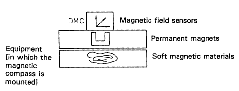
Figure 1 shows in diagrammatic form that the magnetic compass DMC is
mounted in an item of equipment in which the measurements provided by
the DMC are influenced by the combined action of permanent magnets, as
sources of hard magnetic interference, and of soft magnetic materials.
Figure 2 shows the relevant vectors for measuring the earth's magnetic field
and the relevant projections in the horizontal plane. In the case of a
magnetic compass fixedly mounted in a vehicle, the aiming direction
corresponds to the heading of the vehicle.
The electronic magnetic compass possesses three magnetic field sensors
and two tilt sensors; the magnetic field sensors determine three magnetic
field components which do not have to be orthogonal to each other.
The permanent magnets and the electric currents generate a fixed field at
the location of the magnetic field sensors, and said field is expressed as a
shift in the zero point of the coordinate system formed by the magnetic field
components.
From an existing field, the soft magnetic materials generate a weakened or
strengthened field in the direction of the field and additionally they
generate
field components in the directions perpendicular thereto. This can be
regarded as "interference" between the field directions x, y and z.
The same above equations are also obtained if a magnetometer is
considered which possesses three non-orthogonal magnetic field sensors of
different sensitivity and a shift in the zero point, for example like a
"crude"
magnetometer which has not been calibrated by the manufacturer.
CA 02220346 1997-11-06
-6-
The measurement of the magnetic field using such a "crude" magnetometer
can be mathematically expressed as follows:
b9em,~ = f. e, bE, + o. % i = x, y, z
where f; is the strengthening, e; is the measurement direction, i.e. the unity
vector, and o; is the offset of the ith sensor.
If we write f; e; _ (M;,, M;2, M;3) and o; = bo;, we again obtain the above
equation (1).
In order to determine the magnitude of the actual magnetic field of the
earth, it is necessary to resolve the above vectorial equation ( 1 ) according
to bE. By inversion and subtraction, we obtain
bE = M' (bgem - bo) = m(bgem - bo) (2)
where m = M-'
In order to determine the unknown variables M or m = M-' and bo from
equation (1 ) or (2), it is possible to use a solution of the type known from
US Patent 4 686 772, to which reference has already been made. There it
is assumed that, in addition to the measured magnetic field vector b9em, the
earth's magnetic field vector bE is also explicitly known in each case. The
vectorial equations ( 1 ) and (2) represent a linear equation system for the
unknowns M;~ or m;~ and bo; respectively. By conducting measurements in at
least four geometrically different positions, and when the earth's magnetic
field is known, M;~ and bo; can be obtained directly with the aid of
elementary methods to resolve the linear equation systems.
The solution proposed in the above-mentioned US Patent 4 539 760
proceeds from the fact that the value for the earth's magnetic field is
independent of the position of the magnetometer. If the variables m;~ and bo
have been correctly determined, an earth's magnetic field vector bE is
CA 02220346 2004-07-15
obtained which has the same length whatever the position of the
magnetometer. It thus follows that a constant (const) is:
const = b~2 = bETbE = (b9em - bo1'~mTm (b9em ' bo)
_ (beam - bolTU (b9e", - bo) (3)
where UT = U, which means that U is a symmetrical matrix.
It can immediately be seen that this equation (3y can only be used to
calculate the product U = mTm of the sought after matrix m. The elements
of this matrix can be calculated only if it is assumed that this matrix is
symmetrical and if the diagonal is taken to be positive. The first of these_
assumptions applies, however, only in the rarest of cases, because it would
mean a soft magnetic symmetry which is extremely unlikely to exist in
technical equipment such as an aircraft or motor vehicle.
According to the invention, the approach employed to determine the
parameter bE , i.e. to solve the vector equation, makes use of the fact that
in each position of the measuring system at the same geographical location,
the angle between the horizontal plane and the earth's magnetic field, i.e.
the inclination angle, remains constant. This obviously then also applies to
the angle between the direction of the gravitational vector g and the earth's
magnetic field vector bE. We can therefore write:
const =b9 = bESin(i) = grbE = gTm (b9em - bob- (4)
where
b9 = the magnetic field component parallel to the gravitational vector g
b~ = the length of the magnetic field vector bE
and where i is the inclination angle.
CA 02220346 1997-11-06
_8_
This equation states that the component of the magnetic field vector in the
direction of the earth's gravitational field, i.e. perpendicular to the
horizontal
plane, is the same in all positions of the system.
In this equation, the parameter m occurs linearly and not as a product. The
gravitational vector g can be determined with the aid of the tilt sensors.
Therefore, this parameter m can be directly calculated without having to
measure the field as is done in the aforementioned US Patent 4 686 772, or
without having to presuppose special symmetry conditions as in the
aforementioned US Patent 4 539 760.
The number of parameters that need to be determined are as follows:
m = 3x3 = 9
bo = 3
b9 = 1
This results in a total of 9 + 3 + 1 - 13 parameters and at least 13
equations are needed to determine them.
An arbitrary scaling factor can be selected, such as for example is known
from the aforementioned US Patent 4 539 760 (column 4, lines 3 ff).
Possible scales could, for example, be selected from the following list:
b9 = const.
m" = const.
m~ ~ + m22 + m33 = const.
mi~2 + m22Z + m332 = const.
m~~2 + m~22 + ... + m332 = const.
det m = const.
Or another suitable scale could be selected in which the constant is also 1.
By selecting the scale, the number of parameters is reduced by 1, so that
now only 12 parameters remain for which a corresponding number of
CA 02220346 1997-11-06
_g_
equations are required. When initially calibrating the magnetic compass, 12
different geometrical positions j = 1, ...., 12 are adopted at which the three
magnetic field components and the two tilt angles are measured.
A linear equation system is obtained:
b9 = gjTm (b9em,i - bo) = giTm bsem,i - giTUO (5)
where uo = m bo and, for example, b9 = 1, which then explicitly gives:
1 = g;, bgem,, m, 1 + 9;. bgem,2 m12 + ...
... + g~~ uo~ + g~2 uo2 + g;3 uos
If more than 12 equations are available, the best matching can be achieved
here by using, for example, the least squares method, which is generally
known.
Within the framework of the invention the possibility also exists to make
use of the fact that the angle of inclination or b9 is constant at the same
fixed location, together with the fact that the length of the magnetic field
vector (bE = ~ bE ~ ) is constant. Expressed differently, this means that not
only the above equation (5) but also the equation (3) can be used for the
method. Then, the parameter bE must be additionally determined so that the
number N of the parameters and thus the necessary measurements can be
increased by 1 to N = 13.
Advantageously, by using equations (3) and (5) the available data are better
utilized, because each measurement is used in two equations. The number
of necessary measurements is thus halved as a result. To implement this
method, it is necessary to use an observational calculus, which can be
based, for example, on the least squares method.
In the method described below, the above-mentioned equations (3) and (5)
are used in a statistically correct manner.
CA 02220346 1997-11-06
-10-
In the following, the relationship that exists between the magnetic field
sensor signals,u;j; j = 1, 2, 3 and the earth's magnetic field vector bEj is
described in more detail. This relationship can be described by the equation
,uj = ,uo + MbEj + sj ; j = 1, ... N (measurement positions)
N1j
uj = ,u2j measurements of the 3 magnetic field sensors at position j
/U3j
IU01
uo = ,uoz vector for offset and hard magnetic disturbance field
~03
M11M1zM13
M= M21M2zM23 matrix of the soft magnetic distortion
M31 M32M33
bEj = earth's magnetic field vector
Ej - random vector which represents the noise of the sensors
< Ej > = 0; < Ej EjT > = Qu213; < Ej EkT > = 0 j ~ k;
< > = expected statistical value
The components of the earth's magnetic field bEj are not known in the
various positions of the magnetic compass. However, it is possible to
demonstrate them partially with the aid of the tilt sensors. The two tilt
sensors each measure one component of the vector of the gravitational field
which is standardized to 1. This vector runs in the perpendicular direction.
CA 02220346 1997-11-06
-11-
bE~ = s g~ + cr~~
s = sin(i) ; c = cos (i)
bE~ ~ = 1 strength of earth's magnetic field = 1
i - angle of inclination of the earth's magnetic field
r7~ = cos(a~)e~ +sin(a~)f~ ;
where a~ is the azimuth angle, i.e. the angle of rotation of the sensor's
own coordinate system compared with a spatially fixed coordinate
system in the horizontal plane.
= gravitational vector
~ g~ ! - 1
9,; ~1-9zi; ~0
9 = gz; ~ e~ _ ( 1-g~~ z)-~r~ -9~;gz; : f; _ ( 1-g~; z) i2 -gs;
9s; -9,;ga; 9z;
g~~, gz~: tilt sensor measurements, g3~ _ ( 1-g,~z - 9z;2)'~Z
The values of the parameters M ~ ~ ... M33, No, ~ Noz~ Nos~ a, ~ ~ ~ arv and i
can be
determined using a known optimization calculation where, for example, the
minimum is required for the statistical sum
N
L(M. Not ai ... aN, i) - F (~~ - /ao - MbE~)z
j = 1
Various other solutions are possible within the framework of the invention,
e.g. using Kalman filters, fuzzy procedures or neuronal networks.
Thus it is apparent that a substantial mathematical simplification can be
achieved if the parameter DM = 0. This is the case when no soft magnetic
CA 02220346 1997-11-06
-12-
disturbance field needs to be taken into account. M then corresponds to the
unity matrix.
In the description given above, reference was made to tilt sensors. Instead
of these, two orthogonally mounted encoders can also be used. These
would measure angles relative to a reference point. However, in the
practical embodiment, it would then be necessary to provide a firmly
mounted bracket in relation to which the magnetic compass and the
disrupting system would rotate.
It would also be possible to determine the desired tilt angles by means of
two rate of rotation sensors, i.e. gyros, attached to the system. The angles
of rotation can be derived through integration of the rate of rotation
information.