Note: Descriptions are shown in the official language in which they were submitted.
CA 02220413 1997-11-07
A BLOCK FOR THE MORTARLESS CONSTRUCTION OF A WALL
The present invention generally relates to wall
construction, and more particularly to a block for
mortarless construction of a wall, e.g. a wall of a building
structure. The invention also relates to a mortarless wall
erected using such blocks.
The outside masonry walls of buildings are generally
constructed using rectangular bricks assembled by mortar, or
nailed thin asphalt shingles which are difficult to affix
and require a very robust wall.
Known in the art is US patent n° 2,341,971 (Antill), which
describes a sectionally supported wall for furnaces or other
high temperature chambers. The wall comprises an outer
metal supporting structure having hanging members for
supporting sections of the wall consisting of a series of
courses of interengaging refractory rectangular blocks. The
blocks in as course have interengaging small projections and
recesses to engage with complementary r-ecesses and
projections of the adjacent lateral blocks to prevent
lateral displacement of the blocks in the course. Certain
blocks of the course are also provided with small
projections and recesses to engage with the blocks of a
course beneath and/or above, to prevent lateral displacement
of the courses. However, due to the gener-ally rectangular
shape of the blocks, the wall is not adapted for outside
construction because water may infiltrate between the blocks
through spaces or by cavitation, i.e. due to capillary
action and/or under the influence of wind during a rain
storm. Furthermore, installation of the blocks may take
time because they must follow an appropriate pattern to
match with the positions of the hanging members and the
supporting structure.
British patent number 5267 (accepted on June 12, 1902)
1
AMENpEp SKEET
IPEA/EP
CA 02220413 1997-11-07
relates to a brick for use with mortar. This British patent
does not, however, deal with the problem of how to configure
a block or brick for the mortarless construction of a wall.
It in particular does not deal with the problem of how to
inhibit water infiltration nor how ~o facilitate drainage of
water from between adjacent blocks or bricks.
Also known in the art are US patent n° 1,981,324 (Peterson),
2,141,035 (Daniels), 2,323,661 (Hosbein), 2,550, 945
(Steinhage et al.), 2,622,864 (Hasche), 2,823,027 (C.oberly),
3,221,614 (Pertien), 3,870,423 (Peitz, Jr.), 4,441,298
(Limousin), 4,936,712 (Glickman), 5,205.,675- (Hamel),
5,279,082 (Scholta) and 5,337,527 (Wagenaar), which disclose
various types of blocks and wall or pavement structures.
However, none of these blocks and wall structures seem to be
completely satisfactory in all aspects involved in the fast
and steady construction of mortarless walls of buildings.
It would be advantageous to have a block for mortarless
construction of a wall which is relatively simple in design
and inexpensive to manufacture.
It would be advantageous to have a block which may be used
without mortar to construct a wall and which may attenuate
or inhibit the penetration of water between adjacent like
blocks, e.g. due to capillary action and/or the influence of
wind. It would also be advantageous to have a block for the
mortarless construction of a wall which may facilitate the
drainage of water from between adjacent blocks.
It would be further advantageous to have blocks which are
interlockable with like blocks so as to form a wall without
the need for using mortar.
I-t would also be advantageous to have blocks which are
2
APJIEND~? ShE~T
I F~A!~F'
CA 02220413 1997-11-07
able to. attenuate deformations in the construction thereof.
It would also be advantageous to be a:~le to provide a
mortarless wall wh3-ch is steady and easy to construct.
It is to be understood herein that the word "mortar" refers
to any binding agent of any kind whatsoever _incl,uding but
not limited to a binding agent based on cement, lime and
sand, an adhesive, etc... Thus, the word "mortarless" is to
be-understood as characterising a wall whexein the blocks
are not held together by a binding agent.
The present invention in one general aspect relates to a
tongue and mortise block, for- use in the construction of a
wall wherein a plurality of like blocks are stacked in
successive mortarless overlapping courses so as to define a
wall face,
said tongue and mortise block comprising
two side ends spaced apart by
a top face
a bottom face
a front face and
a rear face
said top face comprising a tongue interlock element and
a declining face portion, said declining face portion
connecting the tongue interlock element to the front
face,
said bottom face comprising a mortise interlock element
and a forward face portion, said forward face portion
connecting the mortise interlock element to the front
face,
said two side ends, said top face, said bottom face, said
f ront face and said rear face being conf figured such that ,
3
ANiE~3DED SHEET
IPE~/EP
CA 02220413 2003-09-15
when said block and an underlying, like, block form part of the wall and the
bottom face
of the block engages the top face of a said underlying, like, block such that
the front face
of the block defines a portion of the wall face,
the tongue interlock element of a said underlying block is able to register in
the
mortise interlock element of the block so as to be able to interlock both
blocks such that
to relative forward and rearward displacement is inhibited, and
the front face of the block is vertically offset downwardly relative to the
tongue
element and the rear face thereof.
The present invention also relates to a tongue and mortise block, for use in
the
construction of a wall wherein a plurality of like blocks are stacked in
successive
mortarless overlapping courses so as to define a wall face, said tongue and
mortise block
comprising
two side ends spaced apart by
a top face
2o a bottom face
a front face and
a rear face
said top face comprising a tongue interlock element and a declining face
portion, said
declining face portion comprising a ledge element and a top intermediate
element, said
top intermediate element connecting the tongue interlock element to the ledge
element,
said ledge element connecting the top intermediate element to the front face,
said bottom face comprising a mortise interlock element and a forward face
portion, said
forward face portion comprising a foot element and a bottom intermediate
element, said
bottom intermediate element connecting the mortise interlock element to the
foot
element, said foot element connecting the bottom intermediate element to the
front face,
said two side ends, said top face, said bottom face, said front face and said
rear face being
configured such that when said block and an underlying, like, block engages
the top face
of a said underlying, like, block such that the front face of the block
defines a portion of
the wall face,
4
CA 02220413 2003-09-15
the tongue interlock element of a said underlying block is able to register in
the
mortise interlock element of the block so as to be able to interlock both
blocks such that
relative forward and rearward displacement is inhibited,
the front face of the block is vertically offset downwardly relative to the
tongue
element and the rear face thereof, and
1o the foot element of the forward face portion of the block is able to engage
the
ledge element of the underlying, like, block.
The present invention further provides a tongue and mortise block, for use in
the
construction of a wall wherein a plurality of like blocks are stacked in
successive
mortarless overlapping courses so as to define a wall face, said tongue and
mortise block
comprising two side ends spaced apart by
a top face
a bottom face
a front face end
a rear face
said top face comprising a tongue interlock element and a declining drainage
face
portion, said drainage face portion connecting the tongue interlock element to
the front
face,
said bottom face comprising a mortise interlock element and a forward face
portion, said
forward face portion connecting the mortise interlock element to the front
face,
said two side ends, said top face, said bottom face, said front face and said
rear face being
configured such that, when said block and an underlying, like, block form part
of the wall
and the bottom face of the block engages the top face of a said underlying,
like, block
such that the front face of the block defines a portion of the wall face,
3o the tongue interlock element of a said underlying block is able to register
in the
mortise interlock element of the block so as to be able to interlock both
blocks such that
relative forward and rearward displacement is inhibited,
the front face of the block is vertically offset downwardly relative to the
tongue
element and the rear face thereof, and
the forward face portion of the bottom face of the block and the drainage face
CA 02220413 2003-09-15
portion of the top face of said underlying, like, block are spaced apart and
able to define
side walls of a drainage air gap therebetween.
The present invention in particular provides a tongue and mortise block, for
use in the
construction of a wall wherein a plurality of like blocks are stacked in
successive
1o mortarless overlapping courses so as to define a wall face, said tongue and
mortise block
comprising two side ends spaced apart by
a top face
a bottom face
a front face and
15 a rear face
said top face comprising a tongue interlock element and declining drainage
face portion,
said declining drainage face portion comprising a ledge element and a top
intermediate
face element, said top intermediate face element connecting the tongue
interlock element
to the ledge element, said ledge element connecting the top intermediate face
element to
2o the front face,
said bottom face comprising a mortise interlock element and a forward face
portion, said
forward face portion comprising a foot element and a bpttom intermediate face
element,
sadi bottom intermediate face element connecting the mortise interlock element
to the
foot element, said foot element connecting the bottom intermediate face
element to the
25 front face,
said two side ends, said top face, said bottom face, said front face and said
rear face being
configured such that, when said block and an underlying, like, block form part
of the wall
and the bottom face of the block engages the top face of a said underlying,
like, block
3o such that the front face of the block defines a portion of the wall face,
the tongue interlock element of a said underlying block is able to register in
the
mortise interlock element of the block so as to be able to interlock both
blocks such that
relative forward and rearward displacement is inhibited,
the front face of the block is vertically offset downwardly relative to the
tongue
35 element and the rear face thereof,
CA 02220413 2003-09-15
the foot element of the forward face portion of the block is able to engage
the
ledge element of a said underlying, like, block, and
the bottom intermediate face element of the block and the top intermediate
face
element of a said underlying, like, block are spaced apart and able to define
side walls of
a drainage air gap therebetween.
1o
The opposite lateral side ends of a block may take on any desired shape or
form. They
,.___,_,__,___~~_
CA 02220413 1997-11-07
mate or engage the lateral sides of -adjacent like bricks on
either side thereof to form a joint of desired shape e.g.
flat curved sloped etc. If desired blocks may be placed in
block courses so as not to laterally abut.
A block in accordance with the present invention may take on
any desired aspect. A block may for example take on the
aspect of a brick, a wall tile, etc.; it may of course take
on a more massive aspect as desired. A block may be formed
of any suitable material such as for example of concrete,
clay, resin or plastic material, or any other mouldable
material.
In accordance with the present invention the reference to
the expression "declining drainageface portion" is to be
understood as referring to a face able to avoid water
retention and over which water may freely pass downwardly,
i.e. the face is at least substantially free of depressions,
holes and the like which trap water. The drainage face
portion even if comprising a number of elements is thus
nevertheless configured to have an overall slope such that
when a block is place in a wall, water is able to flow down
the drainage face without being trapped or retained thereby.
Zt is also to be understood, in accordance with the present
invention that the reference to "a drainage air gap" is a
reference to a gap, chamber, aperture, hole, slit and the
like which is sized and configured for attenuating the
infiltration of water between the block and a said
underlying, like, block and/or for facilitating the drainage
of water from therebetween down the drainage face mentioned
above.
The tongue and mortise elements of a block may take on any
desired or necessary configuration. It is, however, to be
kept in mind that these elements are to respectively
8
A F~li ~ ~~ J ~ ~ L ~-; ~ ~-r
~'=fc::y _'
CA 02220413 1997-11-07
cooperate with the mortis and tongue elements of like upper
or underlying blocks) as the casemay be such that when
such blocks are stacked together the complementary tongue
and mortise elements thereof define a nesting pair of
interlocked elements able to inhibit displacement of the
blocks relative to each other by forces acting for example
perpendicularly to the front face. The tongue and/or mortis
elements may for example be disposed so as to be spaced
apart from the side ends of the block, so as to be disposed
adjacent one side end or so as to extend from one side end
to the other side end; again it is to be borne in mind that
the tongue and mortis elements of like blocks are to be
configured so as to be able to interlock the blocks as
described herein. The top face may have a tongue element
formed with convex end part and having a dihedral angle; the
bottom face of the block may be formed with a complementary
concave recesses also having a dihedral angle.
The tongue and mortis elements of a block may for example
both be disposed adjacent the rear face thereof and each may
longitudinally extend from one side end of the block to the
other side end thereof. On the other hand, these interlock
elements may be disposed at some other position intermediate
the rear and front faces if so desired; in this case
however, it must be kept in mind that the top and bottom
faces must be appropriately configured to facilitate the
desired interlocking of like blocks.
r1 +-1-,n"~1, l ; lrc hl nr~lcc arc tr, ha i ni-arl nr~lral-~l a as mant i
snarl
r-a.L~muu.J.m ~.y»~. ~._.y..~.".~. ~..~~. ~... ~._,._.
~~.~..r..............~............. ....~. ...~.~~.~~..........
above, a block in accordance with the present invention may
nevertheless be provided with a mortise element which is
sized and configured relative to the tongue element thereof
so as to permit limited adjustment (i.e. positional
adjustment) of the block perpendicularly to the wall face
when the block is initially disposed on a said underlying,
like, block, i.e. by allowing for a minor
9
AiVIENDED SHEET
tr'~~r~./~r~
CA 02220413 1997-11-07
amount of clearance or play between the tongue and mortise
nested therein, the play being rotational or linear about
the tongue element.
A block may for example have a rear face ~,vhich comprises an
upper rear face element and a lower remaining rear face
element- The upper rear face element is disposed adjacent
the top face of the block and comprises a projection for
engaging a support means disposed opposite the rear face of
the block. The lower remaining rear face element is
forwardly inset relative to the projection of the upper rear
face element. Such a configuration of the- rear face may
advantageously facilitate the above mentioned limited
adjustment.
As mentioned above, a block in accordance with the present
invention may have a top face provided with a declining
drainage face portion. The drainage face portion is
configured to have an overall slope such. that when the block
is place in a wall, water is able to flow down the drainage
face without being trapped thereby. Thus in accordance
with the present invention a block is provided wherein said
ledge element and said top intermediate face element may be
disposed such that the ledge element and the top
intermediate element define an obtuse angle therebetween and
when said block and a said underlying, like, block form part
of the wall and the bottom face of the block engages the top
face of a said underlying, like, block, the ledge element
may be able to be disposed such the wall face and the ledge
element define an acute angle therebetween and the top
intermediate face element may be able to be disposed such
the wall face and the top intermediate face element define
an acute angle therebetween.
A block in accordance with the present invention may, if
desired, include means for allowing the attachment of the
j~-r"-.;~-
CA 02220413 1997-11-07
block to a support means disposed opposite the rear face
thereof (e. g. to a furring). The means for allowing
attachment of the block may comprise an aperture extending
from said top intermediate face element to the rear face of
the black. Such an aperture may be countersum at the top
intermediate side thereof. The aperture may thus be a
straight opening for receiving an attachment means such as
a nail or screw element for f fixing the block to a support
means such as a wall furring.
The means for allowing attachment of a block to a support
means may alternatively comprise a guide groove for
facilitating the drilling of an aperture through the block
from the top intermediate face element to the rear face of
the block, said guide groove being disposed in the top
intermediate face element and extending from one side end of
the block to the other side end thereof.
As mentioned above a block may be configured to cooperate
with a like underlying block so as to form a drainage air
gap_ The drainage air gap may take on any desired form or
shape keeping in mind that its purpose is to attenuate the
infiltration of water between the block and a said
underlying, like, block as well as to facilitate the
drainage of water from therebetween (i_e. due to the sloped
drainage face); the infiltration of water may, for example,
be due to capillary action and/or the influence of wind
acting on the wall face during a rain storm for example.
Thus a block may be provided wherein the top and bottom
intermediate face elements of the block may be configured
such that, when said block and a said underlying, like,
block form part of the wall and the bottom face of the block
engages the top face of a said underlying, like, block, the
bottom intermediate face element of the block and the top
intermediate face element of a said underlying, like, block
are able to define side walls of a drainage air gap of
11
AMENDED SHEET
IPEA/EP
CA 02220413 1997-11-07
wedge-like shape. The wedge shaped gap may have a wide-part
and a lower narrow end, said wide part being disposed toward
the interlocked tongue and mortise elements, said lower
narrow end being disposed toward the engaging foot and ledge
elements.
The above blocks may be incorporated into a wall. The wall
may for example be an exterior wall which is exposed to the
atmosphere, e.g. rain and wind. The wall may if desired be
an interior wall.
Thus the present invention in a further aspect provides a
wall wherein a plurality of like tongue and mortise blocks
are stacked in successive mortarless overlapping courses so
as to
define
a wall
face,
each said tongue and mortise block comprising
two side ends spaced apart by
a top face
a bottom face
2-0 a front face and
a rear f ace
said top face comprising a tongue interlock element
and
a declining face portion, said declining face portion
connecting the tongue interlock element to the front
face,
said bottom face comprising a mortise interlock element
and a forward face portion, said forward face portion
connecting the mortise interlock element to the front
face,
said two side ends, said top face, said bottom face, said
front face and said rear face being configured such that,
when said block and an underlying, like, block form part
of
the wall
and the
bottom
face of
the block
engages
the top
face of a said underlying, like, block such that the front
face of the block defines a portion ofthe wall face,
the tongue interlock element of a said underlying
12
1~~:.~'=r
CA 02220413 1997-11-07
block is able to register in the mortise interlock element
of the block so as to be.able to interlock both blocks such
that relative forward and rearward displacement is
inhibited, and
the front face of the block is vertically offset
downwardly relative to the tongue element thereof,
and
wherein at least some of said blocks include means for
allowing the attachment of such block to a support means
disposed opposite the rear face thereof and at least some of
such blocks provided with means for the attachment thereof
to said support means are attached to said support means by
respective attachment means exploiting respective means for
allowing attachment of the block to the support mean.
The present invention also provides a wall wherein a
plurality of like tongue and mortise blocks are stacked in
successive mortarless overlapping courses so as to define a
wall face,
each said tongue and mortise block comprising
two side ends spaced apart by
a top face
a bottom face
a front face and
a rear face
said top face comprising a tongue interlock element and
a declining face portion, said declining face portion
comprising a ledge element and a top intermediate
element, said top intermediate element connecting the
tongue interlock element to the ledge element, said
ledge element connecting the top intermediate element
to the front face,
said bottom face comprising a mortise interlock element
and a forward face portion, said forward face portion
comprising a foot element and-a bottom intermediate
13
AMENDED SHEET
IPEA/EP
CA 02220413 1997-11-07
element, said bottom intermediate
element connecting the mortise interlock element to the foot
element, said foot element connecting the bottom
intermediate element to the front face,
said two side ends, said top face, said bottom face, said
front face and said rear face being configured such that,
when said block and an underlying, like, block form part of
the wall and the bottom face of the block engages the top
face- of a said underlying, like, block such that th.e front
face of the block defines a portion of the wall face,
the tongue interlock element of a said underlying block
is able to register in the mortise interlock element of
the block so as to be able to interlock both blocks
such that relative forward and rearward displacement is
inhibited,
the front face of the block is vertically offset
downwardly relative to the tongue element thereof,
the foot element of the forward face portion of the
block is able to engage the ledge element of the
underlying, like, block
and
wherein at least some of said blocks include means for
allowing the attachment of such block to a support means
disposed opposite the rear face thereof and at least some of
such blocks provided with means for the attachment thereof
to said support means are attached to said support means by
respective attachment means exploiting respective means for
allowing attachment of the block to the support mean.
The present invention also in particular provides a wall
wherein a plurality of like tongue and mortise blocks are
stacked in successive mortarless overlapping courses so as
to define a wall face thereof,
each said tongue and mortise block comprising
14
AME~'~J~D ~,'--WET
1 i~L. ~:~~ it~
CA 02220413 1997-11-07
two side ends spaced apart by
a top face
a bottom face
a f ront f ace and
a rear face
said top face comprising a tongue interlock element and
a declining drainage face portion, said declining
drainage face portion comprising a ledge element and a
top intermediate element, said top intermediate element
connecting the tongue interlock element to the ledge
element, said ledge element connecting the top
intermediate element to the front face,
said bottom face comprising a mortise interlock element
and a forward face portion, said forward face portion
comprising a foot element and a bottom intermediate
element, said bottom intermediate element connecting
the mortise interlock element to the foot element, said
foot element connecting the bottom intermediate element
to the front face,
said two side ends, said top face, said bottom face, said
front face
and said
rear face
being
configured
such that,
when said block and an underlying, like, block form part
of
the wall and the bottom face of the block engages the top
face of a said underlying, like, block such that the front
face of the block defines a portion of the wall face,
the tongue interlock element of a said underlying block
is able register in the mortise interlock element of
the block so as to be able to interlock both blocks
such that relative forward and rearward displacement
is
inhibited,
the front face of the block is vertically offset
downwardly relative to tha tongue element thereof,
the foot element of the forward face portion of the
block is able to engage the ledge element of a said
underlying, like, block, and
AMENDED SHEET
IPEA/EP
CA 02220413 1997-11-07
the bottom intermediate element of the block and the
top intermediate element of a said underlying, like,
block are spaced apart and able to define side walls of
a drainage air gap therebetween,
and
wherein at least some of said blocks include means for
allowing the attachment of such blocks to a support means
disposed opposite the rear face thereof and at least some of
such blocks provided with means for allowing attachment
thereof to said support means are attached to said support
means by respective attachment means exploiting respective
means for allowing attachment of such blocks. to the support
means.
In accordance with the present invention a wall may comprise
a plurality of bricks arranged in self-supporting,
successive overlapping courses, i.e. the blocks may be
arranged side by side in rows or layers.
A support means may comprise a wall furring means. A wall
furring means may for example be a flat panel of wood
affixed (e. g. affixed to an underlying wall support
structure). Alternatively, said wall furring means may be
a plurality of hcrizontally extending, vertically spaced
rails or strips (of wood) to which at least some of the
blocks of a wall may be affixed (by nails, screws, etc..).
The furring strips for example each having a front
protruding surface, and the rear side of each of the blocks
may have a longitudinal recess shaped to fit with and
receive the protruding surface of a corresponding one of the
rails . The strips of wood serve to space the blocks away
from the underlying support structure so as to provide an
air gap between the back of the blocks and the underlying
wall support structure.
A wall may further comprise base units to provide a steady
_ 16
r~''~ai'J1'._~~~L~~~~ ~~~~ f
~~'~,~~t~'
CA 02220413 1997-11-07
bottom course, each of the base units having a bearing
surface adapted to steadily rest onto an accommodating
structural member having a planar surface. The base units
may have a top face provi.ied with convex dihedral
protrusions shaped to nest in a complementary mortise
element . The base units may also have a pair of opposite
lateral sides shaped to match lateral sides of the adjacent
base units to form said bottom course.
The tongue element may comprise an inset seat portion for
allowing attachment of the block to the support structure,
the seat element being configured to engage a chevron-shaped
bracket affixable to a rear support means. The rear face of
the block may for example be provided with a longitudinal
recess extending between the side ends thereof, the
longitudinal recess being configured and sized to engage a
lining rail affixed to the support means.
In accordance with a wall of the present invention adjacent
blocks of each course of blocks may define a joint
therebetween. The blocks may if desired be stacked directly
on top of one another so as to form a plurality of
horizontal columns of blocks, the joints between columns
being more or less parallel. Alternatively the joints
between blocks may take on a horizontal zig-zag pattern;
such a pattern will facilitate the inhibition of water
infiltration. Thus, in this latter case at least one course
of blocks comprises blocks which engage a respective pair of
adjacent underlying blocks in an underlying course of blocks
and straddle the joint between said pair of adjacent
underlying blocks. If desired, adjacent blocks of each
course of blocks may define a joint therebetween and a
respective block in an upper course of blocks straddles each
such joint and engages the underlying adjacent blocks
defining said respective joint. A straddling block may be
disposed more over one block than another or it may be
17
AMENDED SHEET
iPEA!EP
CA 02220413 1997-11-07
disposed in equal fashion over
the joint of the underlying pair of blocks, i.e. the blocks
may be stacked in staggered fashion.
In drawings which illustrate example embodiments of the
invention,
Figure 1 shows a perspective view of an example
embodiment of a block in accordance with the
present invention, the block being provided
with a longitudinal guide groove interrupting
the top intermediate face element thereof;
Figure 2 is a side end view of the block shown in
figure 1;
Figure 3 is a side end view of a parent block
comprising a pair of blocks as shown in
figure 1 joined at the front faces thereof;
Figure 4 shows the separated pair of blocks obtained
from the parent block of figure 1 in
interlocking relationship;
Figure 5 shows a front view of a block as seen in
figure 1 wherein the tongue element is shown
with an example manufacturing deformation;
Figure 6 shows a front view of a block as seen in
figure 1 wherein the foot element is shown
18
i-~,P~ENDE~ :'~-~,EE~'
cFEam~
CA 02220413 1997-11-07
with an example manu~acturir~g d~:foziaation;
Figure 7 shows a side end view of a block as seen in
figure 1 wherein the tongue and mortise
elements are shown with an example
manufacturing deformation;
Figure 8 shows an enlarged view of the interlocked
blocks of figure 4;
Figure 9 is an enlarged view of the interlocked tongue
and mortise elements;
Figure 10 is an enlarged view of the guide groove;
Figure 11 is anenlarged view of the engaging foot and
ledge elements;
Figure 12 illustrates a block in a straddling
relationship with underlying blocks;
Figure 13 is an illustration of a plurality of blocks
in a staggered relationship;
Figure 14 illustrates a number of like blocks defining
example embodiments of different drainage air
gaps therebetween;
Figure 15 illustrates a number of like blocks defining
additional example embodiments of different
drainage air gaps therebetween;
Figure 16 is a side end view of a further embodiment
of
a parent block comprising another pair of
example blocks joined at the front faces
19
.. .~- ~ ._.~
~...sV. - -
CA 02220413 1997-11-07
thereof ;
Figure 17 shows the separated pair of blocks obtained
from the parent block of figure 16 in
interlocking relationship;
Figure 18 shows a perspective view of an example
embodiment of a modified version of the block
shown in figure 1 wherein the guide groove
has been replaced by tow apertures passing
from the top intermediate face element
thereof to the rear face thereof;
Figure 19 shows a perspective view of a further example
embodiment of a block in accordance with the
present invention provided with a inset seat
for engaging a bracket for attaching the
block to a rear support means;
Figure 20 is a side view of an example embodiment of a
bracket for attaching the block of figure 19
to a rear support means;
Figure 21 is a front view of the bracket of figure 20;
Figure 22 is a partial side view of a bracket of figure
20 shown in place between two blocks of
figure 19;
Figure 23 shows a perspective view of a further
embodiment of a block provided with a side
end slot for attachment to a building
AMENDED SHEET
I PEA/EP
CA 02220413 1997-11-07
structure using a rail ~ Jv..lew cr t-he like;
Figure 24 shows a side elevation view of an example
mortarless wall portion constructed using
blocks as seen in figure 1 attached to a
furring member;
Figure 25 shows a side elevation view of a further
example mortarless wall portion constructed
using blocks as seen in figure 1 attached to
a furring member;
Figure 26 shows a side elevation view of another
example mortarless wall portion constructed
using blocks having a side configuration of
the block of figure 19 but wherein the inset
seat has been replaced with apertures such as
shown with respect to the block in figure 18;
Figure 27 shows a side elevation view of an additional
example mortarless wall portion constructed
using blocks as seen in figure 19 attached to
a furring member;
Figure 28 shows a side elevation view of another
example mortarless wall portion constructed
using blocks as seen in figure 23 attached to
a furring member as seen in figure 26;
Figure 29 shows a side elevation view of another
example mortarless wall portion constructed
21
/~IVi~il4~E~ Si-iEc'~'
IPL~/~P
CA 02220413 1997-11-07
using a further exampl' EmYodi;r:ent of blo._~.ks
attached to a furring member as seen in
figure 26;
Figure 30 shows a side elevation view of another
example mortarless wall portion constructed
using another example embodiment of blocks
attached to a furring member as seen in
figure 26;
Figure 31shows a side elevation view of yet another
example mortarless wall portion constructed
using yet another example embodiment of
blocks attached to a furring member as seen
in figure 26;
Figure 32 illustrates a partial front view of staggered
blocks only some of which are attached to
furring elements;
Figure 33 shows a perspective view of a corner brick
for use in a masonry wall according to the
present invention;
Figure 34 shows a perspective view of a finishing brick
for use in a masonry wall according to the
present invention;
Figure 35 shows a perspective view of another corner
brick for use in a masonry wall according to
the present invention.
22
AMENDED SHEET
IPE~/EP
CA 02220413 1997-11-07
Figure 36 shows a perspecti~-e-. vie_v of another c.:ozner
brick for use in a masonry wall according to
the present invention.
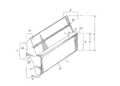
Referring to figures 1 and 2 these figures illustrate an
example embodiment of a block in accordance with tine present
invention. The block 1 has two side ends 2 and 3. The
block 1 has, when viewed in the direction of the arrow 4, a
top face designated by the reference numeral 5. The block
1 has, when viewed in the direction of the arrow 6, a bottom
face designated by the reference numeral 7. The block 1
has, when viewed in the direction of the arrow 8, a front
face designated by the reference numeral 9. Finally, the
block 1 has, when viewed in the direction of the arrow 10,
a rear face designated by the reference numeral 11. The
side ends 2 and 3 are spaced apart by the top face 5, the
bottom face 7, the front face 9 and the rear face 11.
The top face 5 comprises a tongue interlock element 15 as
well as a declining drainage face portion which comprises
ledge element 17 and top intermediate face element 18.
The bottom face 7 comprises mortise interlock element 20 as
well as a forward face portion which comprises foot element
22 and bottom intermediate face element 23.
23
ANl~f~i~~~ S~-1~E"~
(r~f~iEF~
CA 02220413 1997-11-07
A reference line 25 designates the pla.ze of tl~a wall lace of
a wall in which the block 1 may be incorporated. As may be
appreciated the front face 9 would define a portion of such
wall face. As may be seen the ledge element 17 and the top
intermediate face element 18 define an obtuse angel 30; on
the other hand the ledge element 17 and the top intermed:~ate
face element 18 each define a respective acute angle 31 and
32 with the plane of the wall face. As shown the wall face
would be more or less vertical straight up. 'The wall face
if desired may however not be vertically straight up; in
this case care would have to be taken to insure that the
angles between the various elements of the declining face
portion are such as to permit water to nevertheless run down
the declining face portion to facilitate water drainage.
The rear face 11 comprises an upper rear face element 35 and
a lower remaining rear face element 36. The upper face
element 35 comprises a projection 37 which vertically
extends across the entire upper face element 35. If desired
the projection 37 may vertically extend over a smaller part
of the upper face element keeping in mind that the
projection 37 is intended to abut a furring member as seen
in figures 24 and 25. The remaining rear face element 36 is
forwardly inset in the direction of the arrow 10 as may be
seen from figure 9.
24
AMENQE~ SHEET
lPEA/EP
CA 02220413 1997-11-07
The block 1 includes a guide gro«ve 40 wh~_ch extends from on
side end to the other. The guide groove 40 is present to
facilitate the drilling of apertures in the body of the
block 11 in the direction of the arrow 41. These apertures
may be used to secure the block to a rear support member
such as a furring by means of a nail or screw.
As may be seen the tongue element 15 and the mortise element
20 are both disposed adjacent the rear face 11 and extend
longitudinally from side end 2 to side end 3. The tongue
element may if desired not extend form one side end to the
other; e.g. a shortened tongue element may be bracketed
between planar face portions level with the edge of the rear
face. Alternatively, the mortise may not be an open ended
groove -as shown but may be closed off at its ends; in this
case the tongue would of course have to be appropriately
configured so as to be able to nest therein so as to
interlock the blocks. The tongue element 15 includes a
dihedral angle 45; the mortise element 20 includes a
dihedral angle 46.
The rear projection 37 and the remaining rear face element
36 likewise extend from one side end to the other. The
remaining rear face element 36 includes a groove 42 which
may be exploited to fix the block to a support means in a
Af~i'~J~~~ SHEET
f ~Efi/~~
CA 02220413 1997-11-07
manner analogous as shown for erample ir_ figure ?6.
As may be seen from figure 2, the front face 9 is vertically
offset downwardly relative to the tongue element 15, i.e. in
this case the tongue e-lement 15 is vertically higher than
the front face 9.
The front face 9 has upper and lower bevelled edges 50 and
51, to look like a conventional block or brick. The block
may have any suitable length, height and width. The
dimensions of the block 1 depend on the available moulding
process and the bearing capacity of the building foundation.
A width, between the front and rear faces that is suitable
for example for an outside wall of masonry construction, is
approximately equal to 83 mm. Considering the block 1
having a total height P and a frontal height H, then for
example P >_ 1.2H and in particular P = 2H.
As mentioned above the block 1 may conveniently be formed by
concrete, clay, resin, or any other mouldable material.
Referring to figure 3, the block 1 may be obtained by
breaking a parent block 60 along a cleavage line 61 defined
by upper and lower cleavage grooves 62 and 63.
Referring to figure 4, this figure illustrates the two
26
.:~:~',rf ~ J~ '~' i===
._ ,~ , ~ -,
i 'u
CA 02220413 1997-11-07
blocks 1, obtained from the parent blo~k ~0, it interl~cking
relationship such that relative forward movement or
displacement in the direction of the arrow 10 and relative
rearward movement in the direction of the arrow 8 is
inhibited. However it is to be noted that for the
configuration of the block 1 if only the two blocks 1 are
considered by themselves as shown there is no relative
lateral interlocking; for a wall such lateral locking is
achieved by fixing at least some of the blocks in place by
attaching them to a rear support means.
As may be seen from figure 4, with one block 1 disposed over
a like block 1, the bottom intermediate face element 23 of
the upper block and the top intermediate face element 18 of
the lower or underlying block define the side walls of a
drainage air gap 66 disposed between the upper and lower
blocks 1. The gap 66 has wide part 68 dispose toward the
interlocked tongue and mortise elements; the gap 66 also
has a lower part 69 disposed towards the engaging foot and
ledge elements. The dimensions of the air gap 66 may vary
keeping in mind its purpose, e.g. inhibit infiltration of
water by capillarity behind the wall.
Referring to figures 5, 6 and 7, these figures illustrate
possible deformations of the block from the true or perfect
27
AMEf~IDED SHEET
IPEA/EP
CA 02220413 1997-11-07
shape thereof; the deviations are ~PSignated by she
reference numerals 70, 71, 72 and 74.
Referring to figure 8, 9, 10, and 11 these figures show in
more detail certain aspects of the interlocked the blocks 1.
Although as mentioned above the blocks 1 are interlocked so
as to inhibit movement thereof, certain of the block
elements may be sized so as to provide a limited clearance
so as to give the blocks some limited play for adjusting the
relative dispositions of the blocks to attenuate the
aforementioned deformities, i.e. for avoiding uneven
stacking caused by small deformations due to manufacturing
thereof. The possible clearances are designated by the
reference numerals 75, 76 and 77 in figures 9 and 11; the
clearance may thus allow for some minor linear movement in
the direction of the arrow 80 and/or some minor rotational
movement in the direction of the arrow 81 i.e. rotation for
example about point 82. As may be seen from figure 11 the
foot element does not engage the underlying ledge element
over its entire face , i . a . at the front part there is a
clearance 85. Also as may be seen from figure 9 the lower
remaining rear face element of the rear face is inset
forwardly relative to the projection 37 an amount indicated
generally by the reference numeral 88.
28
A 1I~ E''.~ ~ t~ C~ t ;-E E-1'
6t~~A~/~t~
CA 02220413 1997-11-07
Figures- 12 and 13 generally illustrate ho~~~ course= of .blocks
such as block 1 may be stacked--in staggered fashion; as seen
in figure 12 the central block 89 is disposed equally on
both sides of the joint 90. It is to be understood, however
that the benefit of the zig-zag joints may also be obtained
if the block 89 is displaced to one side such that it is no
longer disposed equally about the-joint 90, i.e. as long as
the joint 90 is covered water infiltration along the
vertical joints may be advantageously inhibited relative to
- the case where the vertical joints extend vertically in a
straight line between columns of blocks.
Referring to figures 8 and 12 an upper block 1 may bear on
the underlying block 1 at both the tongue element and the
ledge element or if desired, provided that adequate
interlocking is achieved, substantially only on the ledge
element.
In accordance with the present invention the expression
"like blocks" include blocks which while not exactly
identical are nevertheless able to interlock as described
herein and as the case may be have top and bottom
intermediate face elements which are able to define a
discharge gap therebetween. Referring to figures 14 and 15
the figures show blocks 1 being interlocked with like blocks
29
-~..:~~', ~.., _._ -_ . ''~w '. -
;.J
CA 02220413 1997-11-07
_ 95, 96, 97 and 98 and 99. The like blocl=s 95, 96 98 arid 99
have projections on the intermediate faces elements thereof
which may be considered to divide the respective air gap
into a number of communicating decompression chambers for
accentuating the attenuation of water infiltration due for
example to wind action in the presence of rain. These
projection all have sloping upper surfaces 102, 103, 104,
105, 106 and 107 such that the projection do in trap water.
although the air gap has been shown in the drawing to be of
more or less wedge-like shape the air gap may take on any
other desired shape provided that it is still a drainage air
gap. Turning to figures 16 arid 17, these figures show an
additional alternate block configuration and a consequential
different air gap configuration; the air gap being
designated by the reference numeral 110. The parent block
112 is cleavable in the same manner as the parent block 60
along a cleavage line 115 to form two blocks 117. The
blocks 117 are of the same configuration as block 1 except
for the configuration of the bottom intermediate face
element 120.
Figure 18 also shows an alternate block configuration. The
block 122 is the same as block 1 except that block 122 does
not have the guide groove 40. In place of the guide groove
AMENDED SHEET
IPEA/EP
CA 02220413 1997-11-07
40 the block 122 has two, apertu=ec 12'.' a- d 12 E. w:~ich ~:xtsnd
from the top intermediate face element to the rear face 11.
The apertures may be countersunk to seat the head of a screw
for example as indicated by the dotted circle 129.
Referring to figure 19, a further example embodiment of a
block is illustrated. The block 130 is the same as the block
1 except for number of features. the block 130 does not
have a guide groove 40; instead the block 130 is provided
with an inset seat 133 for engaging a bracket for fixing the
block to a rear support means. Additionally the top
intermediate face element 135 is recessed relative to the
top intermediate faced element 18 of block 1. Finally the
bottom intermediate face element 136 is not recessed as is
the case for the bottom intermediate face element 23.
Referring to figure 26 the like blocks 130 are able to
define air gaps 138 of wedge like shape.
Referring to figures 20, 21 and 22 these figures illustrate
an example bracket 140 having a portion 141 configured for
engaging the inset seat 133 of block 130. The bracket also
has a portion 142 for engaging a fastener such as a screw
for attaching the bracket for example to a wall furring
means. The portion 142 is provided with an opening indicated
by the reference numeral 144 for receiving a screw (not
31
A.~I;E~sDE ~ S!-~EET
~ i.'"'... ~ j I:'. ~7
CA 02220413 1997-11-07
shown) in the direction of the arrow 14~; the space 146 is
sized relative to the screw head such that the screw head
does not engage the upper block 130.
Referring to Figure 23, there is shown a modified embodiment
of the block 130 shown in figure 19. The bloCK 145 insLeaa
of having the inset seat 133 has slot groove 147 for
receiving a nail or screw for example. the top intermediate
face element 150 is provided with projection elements 152
and 153.
Referring to figure 24 this figure shows a portion of
mortarless wall structure using the block 1. A screw 154 is
used to attach one block 1 to a horizontal wall furring
element 155.
Referring to figure 25, this figure show a portion of
another mortarless wall structure wherein one of the blocks
is also attached to a wall furring 156 by a screw 157. The
block are supported by a base member 158 which is configured
to supportingly engage the first row of blocks; the base
member158 is maintained in place by screws (not shown).
Referring to figure 26, there is shown a portion of a
mortarless wall structure. The structure includes a wall
32
~~il~~~f'~:.~~i_.r'~ C,'W.='~ 3
ir-~=~..='''~"
r --
CA 02220413 1997-11-07
furring means comprising a pl~zra~ =tar of horizontally
extending, vertically spaced rails 160 each affixed to an
underlying wall member 160a having a front protruding member
164, and the rear face of the blocks 165 which are a variant
on the blocks 130 have a groove 42 shaped to fit with and
receive the protruding member 164 of a corresponding one of
the rails 160. The rails space the rear of the blocks away
from the underlying wall member so as to provide an air
space therebetween. The rails may be made of~metal or wood
or any other suitable material.
The mortarless wall structure shown in figure 26 further
comprises base units 166 having a base rear part 167
engaging a support base and a front part 168 configured to
engage the bottom face of an overlying block 165.
Referring to figures 28, 29, 30 and 31 these each show a
wall structure analogous to that seen in figure 26 except
that different block structures are used. Figure 28 shows
a wall structure using the block 145 of figure 23. Figure
29 shows a block 170 wherein the foot element 171 does not
engage a lower ledge element of an underlying block 170.
Figure 30 shows a block 175 which has a counter sink for the
head 176 of a screw but does not form an air gap between top
and bottom intermediate face elements. Figure 31 shows a
33
AMEI~IDED SHEET
IPEA/EP
CA 02220413 1997-11-07
block 180 which has a counter pink fcr .he read' 17G of a
screw but does not form an air gap between top and bottom
intermediate face elements and does not have foot and ledge
elements.
Referring to figure 27
this figure
shows a portion
of a
mortarless wall structure wherein the block are blocks 130
of figure 19 and one of the blocks 130 is shown as being
held in place furring 185 by a bracket 140 by
against a
means of a screw 186. The first row of blocks 130 is
supported on base elements configured to
187 which are
engage the bottom face block 130. The ba se elements 187
of
L L _ F. . ....
are in tur n supported to ~m ~utring
by a base member
fixed
185.
Figure 32 shows a front view of a portion of a mortarless
wall structure wherein only some of the blocks are attached
to wall furrings 190 by attachment means represents by a
small circle one of which is designated by the numeral 192.
The underlying bas support members 194 are all attached to
an underlying wall member.
As shown on Figures 33, 34, 35 and 36, the mortarless
masonry wall may further comprise finishing units for
corners (Figures 5, 7 and 8) and windows (Figure 6), each
being shaped to match with the block 130 (as.shown in
34
Ali~~~l~~U ~~~ET
i ~~.~i '~'
CA 02220413 1997-11-07
Figures 19) while providing the r«qu~Ye~ shape t~ form the
corners and windows.
~_ . r- A. ° : ' t ~ _ .__
~.: ~ : ._. , . _~ _ . ~ . __ _. .
r~ - _.Y