Note: Descriptions are shown in the official language in which they were submitted.
CA 02220456 1997-ll-27
W 096/38218 PCT/CA96/00344
-1 -
FLUE GAS SCRUBBING AND WASTE HEAT RECOVERY SYSTEM
Field of the Invention
The patent relates to flue gas scrubbing systems. More particularly, the invention
~ relates to wet scrubbing towers for the removal of undesirable air pollutants (e.g.
particulates, acid rain gases, organic toxins, odours, etc.) from a flue gas PYh~ t stream
produced by in~ tri~1/commerciaVi~ iQn~l (ICI) boilers, especially for the removal of
5 nitrogen oxides (NOx)-
Background of the Illv~l~lion
The incentive to develop a cost-er~;Live technology designed to reduce NOX
Pmi~ion~ from all stationary combustion sources was provided in 1990 through thePn~ctn~ent by the U.S. Congress of the Clean Air Act .~men~1mentc (CAAA). A recent
publication (EPA~53/R-94-022) by the Envil.".",ent~l Protection Agency (EPA) clearly
in-lic~tPs that the new NOX rer11lring timetable is to be applied to ICI boilers (which range
in heat input size from 0.4 to 1,500 MBtu/hr), specifically those that emit over 25 tons of
NOX per year. Such an annual NOX emission rate can be achieved by an oil bllrning
furnace rated at 5MW or a gas-burning furnace rated at 10 MW.
There are a number of ways in which NOX emissions can be reduced in exi~tinp
boilers. Modifications in the combustion process are usually the simplest and cheapest.
Typical examples are a) to switch to a low N-cull~ fuel; b) to ",;";",;~ the use of
excess air; c) to lower the combustion t~ eldLLL.e by injecting water or steam, d) to
decrease the residence time in the flame zone; e) to recirculate and reburn all or part of
20 the flue gases, f) to install an after burner, or g) to retrofit with a new low NOX burner.
Other NOX re~llcing technologies involve some forrn of trç~trnent of the flue gases. The
three main sub-groups are a) the selective catalytic reduction (SCR) or the selective non-
catalytic reduction (SNCR) reaction between NOX and ammonia (or urea) to N2; b) the wet
scrubbing of the gas stream with an oxidant (to convert NO to the soluble NO2 or with a
25 NO-specific absorber; or c) the creation of short lived but highly reactive free radicals by
means of electrical discharge.
Of the retrofit technologies ~ lcllLly popular with the owners of ICI boilers, in
terms of NOX reduction, the triple modification involving a change to natural gas,
in~t~ tion of a new low NOX burner, and recirculation of the flue gas for a reburn appears
SUBSTITUTE SHEET (RULE 26~
=
CA 02220456 1997-11-27
W 096/38218 PCTICA96/0034
--2--
to be the best. However, the selective catalytic reduction in~t~ tion (SCR) appears to be
the only flue gas tre~fment technology receiving favour, despite its high in~t~ tion costs.
The SCR technology is ~ lLly recognized both by the industry and the EPA as the Best
Available Technology (BAT~ because it is able to reduce NOX emi~inn~ from both gas-
fired and oil-fired boilers by over 80%.
Non-catalytic NH3 in-ll7c e-1 NOX reclllrti- n (SNCR) replaces SCR when coal is
burned or when high-sulfur CO,.~ g fuels are used. The main advantage to SNCR over
SCR is that it is twice as cost effective even though it seldom achieves NOX reductions
better than 60%. Its main disadvantage is that it requires high ~ue gas tempel~Lu,cs,
10 generally above 800~C. However, most ICI boilers are now equipped with econ~.,"i,~
which reduce the flue gas temperature to 300~C or less.
CUL1C;IIL1Y~ con~i~lPr~qble lcsea-~,h activity involves the application of the electrical
discharge to fiue gases, e.g. pulsed corona discharge, dielectric balrier discharge, DC glow
discharge, E-beam, etc. The int~-ntion is to produce short lived free r~-lir,~l~ that will react
15 spontaneously with NOX molecules, hopefully to reduce most of them to N2 without also
red~lcin~ the CO2 molecules to CO. High in~t~ tion costs as well as ~nticip~tefl high
ope~ lg and ~ PI~nre costs appear to be the main impe~iment~ to the
commerci~li7~fi-)n of these technologies. A second problem is that the electrical discharge
produces the OH radical (as well as O, H, O3 radicals) which reacts with CO and N2 to
20 produce the NO, leading to an increase rather than a decrease in NOX.
It is a major disadvantage of all the above-described measures and systems for the
reduction of NOX emissions that they require either non-recn~ing or cc)n~t~nt non-
recoverable capital expenditures. Thus, a more economical NOX emissions reduction
method and system is desired.
The creation of oxygen radicals (O or O3) during the oxidation of yellow
phosphorus (P4) has been common knowledge for many years (Thad D. Farr, Phosphorus.
Properties of the Element and Some of its Compounds, T~nn~c~ee Valley Authority,Wilson Dam, ~l~h~m~ Chem. En~. Report #8. 1950, J.R. Van Wazer, Phosphorus and its
Compounds, Interscience, New York 1958). The suggestion to introduce P4 into the spra~
30 of a wet scrubber to oxidize NO to N2 in the flue gas stream from a boiler was made by
S.G. Chang and G.C. Liu (Nature. 343:151-3, 1990). Following bench top
experimentation, the authors (S.G. Chang and D.K. Lee, Environment~l Prog., 11:66-73,
SUBSTITUTE SHEET (RULE 26~
CA 022204~6 l997-ll-27
W O96/38218 PCT/CA96/00344
--3-
1992) suggested the economic feasibility of reduced NOX emissions by means of the P4-
in(l~lcel1 conversion of NO to NOz in a wet scrubber, especially if costs could be recovered
through the m~rketing of the phosphates captured in the scrubbing liquor. However, the
~o~ sion of the disclosed bench top experiment~ to a full-scale industrial application is
5 not readily achievable without overcorning a number of serious engineering problems. P4
is highly reactive and must always be kept and handled hermetically, i.e. away from air,
which poses engineering problems when a con~ L stream of relatively large amounts is to
be h~n~lle~l Further~nore, to form a liquid/liquid emulsion between P4 and water, the
lt;..l~,LdLule of the spray must never fall below 45~.
The location of the P4/NO interaction in the spray of the scrubber as suggested by
Chang et al. makes it difficult to ensure total cf..,ri..e...ent of all undesirable reaction
products, i.e. ozone and ph~ sph~ rus oxides. Furth~more, the P4/NO interaction in the
liquid/gas intPrf~-e in a wet s.ilul~b~ makes it ~lifflclllt to achieve the o~Lillluul PIN molar
ratio necessary for cost t;rr~ iv~I-ess. Other problems with the suggested introduction of
15 P4 into the liquid spray of a wet scrubber are that the leSt;l voh at the bottom of the wet
scrubber cannot contain excess P4 if the lc:sel VOil must be clarified or filtered and that the
efficiency of the reaction between the oxygen radicals and the NO molecules is dependent
on the residence time of the re~ct~nt~ in the spray tower. Finally, the reactions which take
place between P4 and NO are believed to occur in the vapor phase. Thus, ~ 1ition of the
20 phosphorus to the scrubbing liquid spray would in many respects be disadvantageous.
These problems are now overcome with the method and system in accordance with
the invention wherein the P4/NO interaction occurs in the flue gas manifold u~ ealll of
the wet scrubber and independent of any wet s.;l,ll~illg steps. This relocation and
separation permits i) the mt~x~ ion of safety with respect to P4 storage and h~n~1ling; ii)
25 the ~li-"i~I;on of the P4/NO interaction in the vapor phase; and iii) the co-"~i--",ent of
all hazardous bi-products. Furthermore, the method and system in accordance with the
invention further provides for economical pollution control by combining wet scrubbing
operations with waste heat recovery. Thus, a scrubbing system in accordance with the
invention combines ozone-induced oxidation of NO to NO2 with wet scrubbing and heat
30 recovery. The end result is a superior anti-pollution retrofit system which is capable of
removing over 80% of the NOX gases along with about 95% of SO2 and 99% of
particulates, and which also permits energy recovery and utilization if required.
SUBSTITUTE SHEET (RULE 2B~
CA 02220456 1997-11-27
WO 96138218 PCT/CA96/0034
SummarY of the Invention
It is an object of the present invention to provide an NOX emissions reduction
system and method which overcomes the above technological and ecnnnmic~l problems.
It is another object of the invention to provide an NOX emi~ n~ rerlllrtinn system
5 and method which is comhin~1 with waste heat l~CO~
It is yet a further object of the invention to provide a total pollution control and
waste heat recovery system which permits the c~ .e~l removal of SOx and particulates
and which allows for the recovery of associated capital expenditures.
Accordingly, a system in accordance with the invention for re-1neing the NOX
10 content of a flue gas, inclll(les me~ns for ~ L~ a P4 in water liquid/liquid emulsion;
means for injecting a metered arnount of the em~ ion as a mist into the flue gas, and
means for removal of NO2 and phosphnrus oxides from the flue gas. The means for
removal is poeitiQne~l at a selecte~l location dow~LL~ l of the means for injecting so that
the phosphorus-accelerated t~ *c~n of NO in the flue gas in-lnce~l by injection of the
15 ~mnl~ic)n is ~ h~ 11y complete prior to the removal of NO2
The means for removal is preferably a wet scrubbing tower and the means for
injecting is preferably an ~I~....i~el nozzle po~i*one~1 in the flue gas stream and at a
selçc.tecl location u~ e~ll of the scrubbing tower so that the phosphorus acceler~te~l
oxidation of NO in the flue gas in~ e~l by injection of the emulsion is ~b~ lly
complete prior to contact of the flue gas with an aqueous scrubbing liquid in the scrubbing
tower.
The means for pl~illg the P4 in water .-mnl~ n preferably inclllfles a heated
water bath for meltinp solid phosphorus stored in a cont~iner, the Coll~ .Gl being
completely submersible in the bath to ~l~vt;l.l contact of the phosphorus with air, an
emulsion tank sealed from ambient, a means for supplying liquefied phosphorus from the
container to the emulsion tank, and means for ~lmi~ing the liquefied phosphorus with
water at a preselected ratio and in the emulsion tank. In the pl~r~lled embodiment, the
system preferably further includes means for washing the liquefied P4 with a solution of an
acid-dichromate to remove trace c~ ntc
The scrubbing tower preferably includes a sump for collecting spent scrubbing
liquid and a scrubbing liquid conditioning circuit for recovering from the scrubbing liquid
heat energy taken up from the flue gas.
SUBSTITUTE SHEET (RULE 26
CA 02220456 l997-ll-27
WO 96138218 PCT/CAg6/00344
According to another aspect of the invention there is provided a method for
retlllcing the NOX content of a flue gas, which inch1dec the steps of
g a P4 in water liquid/liquid em~ ioIl;
injecting a selected amount of the emulsion as a mist into the flue gas and at a5 pre.selecte-1 location; and
removing NO2 from the flue gas at a distance downstream from the prerle~rmin~d
location, the distance being selecte~l sueh that the phospht~rus-accelerated oxitl~tinn of NO
in the flue gas in~ ce~ by injecting the ~mlll~io~ is subst~nti~lly complete prior to the
removal of NO2-
The flue gas is preferably contacted with an aqueous scrubbing liquid for removal
of NO2 and phosphorus oxides. The t-ml~ n is advantageously prepared by heating solid
P4 in a water bath to ~ /t;nt contact of the phnsrhl~rus with air and ~rlmixing the liquefied
P4 with water in a preseleeted ratio and under a N2 ~tmosph~re.
In yet another aspeet, the invention provides a system for reclllcinp~ the NOX eontent of a
15 flue gas whieh inclu(les a wet serubbing tower having a flue gas tre~tment ehamber, a flue
gas entry port for introdueing a stream of flue gases into the tre~trnent ehamber, a spray
assembly for introducing scrubbing liquid into the stream of flue gases in the tre~tment
chamber, a scrubbing liquid sump for collecting used scrubbing liquid, and an ~.xh~ t for
treated flue gases. The phosphorus ~.mlll~inn injection system includes means for
20 ~r~aLillg a P4 in water liquid/liquid emulsion and means for injecting a metered amount of
the emulsion as a mist into the flue gas prior to entry into the scrubbing tower, the means
for injecting being positioned at a selected location upstream of the flue gas entry port so
that the phosphorus accelerated t ~ ti~n of NO in the flue gas is ~u1~ 11y complete
prior to contact of the flue gas with the scrubbing liquid in the scrubbing tower.
25 Brief Description of the Drawings
Other aspects and advantages of the invention will become a~pal~llL from the
following detailed exemplary description of the ~l~f~l~d embodiment, reference being
made to the drawings, wherein
Figure 1 is a schem~tic diagram of the ~lefelled embodiment of an NOX emissions
30 reduction system in accordance with the invention;
SUBSTITUTE SHEET (RULE 26
CA 02220456 1997-11-27
W 096/38218 PCT/CA96/00344
Figure 2 iS a s~h~m~tic block diagram, ilhlxfr~tin~ the interaction of the
components shown in Figure 1 plus all ~c~ixo, ~ eqnirm~nt related to molliLul"lg and
control of the key v~ri~hles to m;lx;.,.;~ effic,iency, safety and c~."l;1;,enf, Figure 3 is an enlargement of Section A in Figure 1, and
Figure 4 is an enlargement of Section B in Figure 1.
Detailed D~ yLion of the P.~f~.Icd Embodiment
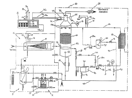
In the ~lertll~d embodiment, illnxfr~te-l s-.h~.m~tically in Figure 1, the system in
accordance with the invention includes a rhl~srh~rus h~nt11ing and injection system 10 and
a wet scrubbing and waste heat recovery system 50. The pht).~rh~rus h~n-lling and
10 injecting system co"xixL i of phosphorus storage and emulsifying stations A and B and a
ph~ cphQrus emlllxion injection arrangement C which will be described in more detail
below with reference to Figures 3 and 4 respectively. The wet scrubbing and waste heat
ecovtl~ system 50 inclll-le~ a wet scrubbing tower 52 and a scrubbing liquid conditioning
and heat recovery circuit 54.
In the ~l~r~lled process in accordance with the invention which is illustrated by
way of a flow diagram in Figure 2, a P4 in water liquid/liquid ~m~ i(m is injected into a
flue g~ stream by way of the injection arrangement C. Injection takes place uysLI~;~ of
the wet scrubbing tower 52 and the exact location is selected such that the phosphorus-
accelerated oxidation of NO in the flue gas is subst~nti~lly cnmrlete prior to contact of the
flue gas with the sc,.ubbillg liquid. The distance of the injection point from the scrubbing
tower 52 can be calculated from the speed of the flue gas stream at the injection point and
the reaction time required for oxi~l~ti~ n of the respective amount of NO present in the flue
gas, which time can be ~l~t~ormin~l from data available in the lik;ldLule.
The scrubbing tower 52 removes water soluble gases (inchl~ling acid gases and
greenhouse gases) and particulates from the flue gas and functions also as direct contact
gas-to-liquid heat exch~nger. The primary scrubbing liquid is preferably water which is
chemi~lly treated and pH balanced and is introduced at the top of the tower 52 through
spray nozzles 58. The scrubbing liquid then passes dowllw~d inside the tower 52,through a structured intern~l bed 60 (Glitsch, Canada) which provides a large surface for
efficient mass and heat transfer. The scrubbing liquid collects in a sump 62 at the base of
the tower 52. Hot flue gas is fed into the tower 52 above the surnp through a flue gas
inlet port 72 and flows upward counter to the dowllw~LLd flow of the scrubbing liquid.
SUBSTITUTE SHEET (RULE 26~
CA 02220456 1997-11-27
WO 96/38Z18 PCT/CA96J00344
The le.~ly~ldLul~ of the liquid is selected to perrnit water vapour con~ n~tion, hence the
transfer of both latent and sensible heat from the flue gas to the scrubbing liquid. The
heated scrubbing liquid is pumped from the sump 62 to a heat ~xch~n~er 64 (Nixon-
Vicarb, Newmarket, Ontario). In Lldl~irc;llillg the liquid through the heat ~xc~h~n~er, the
~ S scrubbing liquid is cooled before it is recirculated back to the spray nozzles 58 at the top
of the tower 52 while a cooling liquid also circulating through the heat exchanger 64 is
heated to the same extent the scrubbing liquid is cooled. The heated cooling liquid can
then be employed for the heating of the boiler plant or other b-lilcling~, for the ~l~aLdLion
of hot utility water, or the like. The energy stored in the cooling liquid which is not used
10 up in the boiler plant and in the scrubbing process, for example for the heating of the
ph~sphorus as will be described in detail below, can be sold to commercial or resi~lenti~l
con~ -m~r~ This allows recovery over time of all or at least a substantial part of the
operation and ~ul~ ase costs of the scrubbing system. Thus, the heat recovery aspect of a
system in accord~lce with the invention provides the system with a significant economical
15 advantage over conv~ntinn~l flue gas scrubbing and especially NOX reduction systems
which do not allow for amortization of the purchase, in~t~ tion and o~ dlillg costs
l~,, ou~ h the sale of recovered energy. A variable speed ~xh~ t fan 68 located at the
exhaust 70 of the tower 52 is ~ntom~tically controlled to vary the draft through the tower,
thereby controlling static ~ Ule and ,.~ i..;.,g the required boiler operation
20 ~ llcters.
The scrubbing tower 52 is usually installed in close proximity to an existing smoke
stack so that the flue gases can be most conveniently and economically redirected from the
bottom of the stack (not shown) to the inlet port 72 of the tower. The scrubbing tower 52
is tlimen~ioned to receive the full volume of the exhaust stream, to extract the m~rim~l
25 amounts of sensible and latent heat as the gases are cooled, preferably to 38~C, and to
capture particulates, SO2 and NO2. The efficiency of these heat and mass transfers are
dependent on the size of the gas/liquid surface int~ e in the scrubbing tower, the
opposing countel~;u.lelLt temperature gradients (decreasing upward for the gases, increasing
d~wllw~ud for the liquid), the selection and m~int~n~n~e of the liquid/gas ratio, the
30 selection and m~int~n~nce of the final exhaust temperature, the selection of the buffer used
for the control of the scrubbing liquid pH and the scrubbing liquid temperature.
SUBSTITUTE SHEET (RULE 2~
CA 02220456 1997-11-27
WO 96138218 PCT/CA96/00344
O~ ;c n of the pollution control and heat recovery process is achieved by a
monitoring system which in(~ les ple~ and temperature seneors 74, 76, a pH sensor
78, (Base Controls, Newm~rket Ontario), the exhaust fan 68, a circulating pump 81
(Pump Tech Inc., ~ieeie~ng~ Ontario) in the scrubbing liquid circuit 54, a central
controller 82 and a buffer liquid mPt~rinp~ pump 84. The sensors 74, 76 and 78 are
electrically connected through associated con~1~lctc-re 74a, 76a and 78a to the controller 82
for the transfer of signals l~)les~ ;--g the size of the variable respectively ~1e~te-cte~ The
controller 82 in turn is electrically connected to the eYh~llet fan 66, the circlll~tinp: pump
81 and the mP.te.rin~ pump 84 through aesociated con~uctQr.e 66a, 81a and 84a for control
10 of the flue gas flow, the throughput of the scrubber liquid conClitioning and heat recovery
circuit 54 and the temperature and pH of the S~ilul~illg liquid ejected from the spray
nozz~es 58 respectively according to parameters stored in the controller. The throughput
of circuit 54 can also be controlled by an electrically controlled mocl~ ting valve 75 (Base
Controls, Nepean, Ontario) ct nn~octe-1 to the controller llllou~ll conductor 75a. Multiple
15 heat e~h~ngers 64 (not shown) can be provided in combin~tion with a s~lubl~ g liquid
distribution arrangement (not illustrated) so that a snfficipntly large he~teink is always
available for the transfer of energy stored in the scrubbing liquid. Furthermore, to
o~li-l-i;~e the particulate and dissolved compound removal from the flue gas, the
eldLule and amount of the s~;lul,bing liquid sprayed into the flue gas is controlled such
20 that the final exhaust temperature is below the dew point (less than 50~C). This allows for
the ca~L~-."g of both the sensible and the latent heat from the flue gas. The sump 62 of
the scrubbing tower receives the sprayed liquid plus the water vapour c~-n-lPnee~l from the
flue gas. The liquid in the sump 62 also contains all the el-L d~L,ed particulates and the
dissolved gases, which were converted to acids and then neutralized by the buffer in the
25 scrubbing liquid. The sump has a make-up water supply 86 and is preferably equipped
with a conventional ~lt- m~tic ball float valve 88 for liquid level control. However, due to
con~lPne~tion of the water vapour originally in the flue gas strearn, there is usually an
excess of water in the sump relative to the requirements for scrubbing liquid recirculation.
Thus, in general, some liquid is directed either continuously or int~rmitt~ntly to drainage
30 through drainage valves 90. This can be done either before or after clarification and/or
filtration of the scrubbing liquid in filter 92, in this embodiment (EMCO Process
Equipment, Mieeies~ug~ Ontario). An ~lk~linP buffer liquid for the control of scrubbing
SUBSTITUTE Sl IEET (RULE 26~
CA 02220456 l997-ll-27
W O 96/38218 PCT/CA96/00344
_9_
liquid pH is supplied to the scrubbing liquid circuit 54 from a buffer liquid storage tank 98
through metering pump 84 which is electrically cormected to central controller 82 through
contlllct r 84a. The storage tank 98 is provided with a mixing arrangement 100 for the
constant or illlrl ~lillrlll mixing of the buffer liquid, depending on the buffer liquid
S respectively used. The ~l~;re.l~,d buffer cQmpounds are Na2, C03 and/or NaHCO3, which
are stored in an aqueous solution in the buffer liquid storage tank. Make-up water can be
added to the buffer liquid storage tank 98 through a make-up water line 94 and make-up
water valve 96. A scrubbing liquid bypass circuit 102 is provided in the scrubbing liquid
circuit 54 which allows for ,~,~",le"~,~ce and repair of the filter 92 as well as control of the
10 scrubbing liquid throughput thereof.
Wet scrubbing towers of this principle construction and function have been used to
clean the t-xh~ t of various power plants (Tilsonburg District ~en~ori~l Hospital,
Tilsonburg, ON; Ottawa Civic ~ospit~l, Ottawa, ON; (J~qtin~l Sewage Tre~tment Plant,
('T~tine~ll PQ) rated from 20 to 60 ~tu/hr. All function to recover and utilize waste
15 heat. In terms of antipollution p~lrO. " ,~ e, these scrubbing systems in general remove
over 95% of particulates and ~h~ lly all of the SOx gases, but only up to 50% of the
NOX gases. This ~r~. ",~nce is now Illlpiov~d by the ~ liti~n of the ph~ sphnrus h~nt11ing
and injection system in accordance with the invention.
The NOX gases consist of N2O, NO, and NO2. The capture of each by a scrubber
20 depends on its aqueous solubility and on the ease by which it can be L-~r~,lllled (through
chemic~l interactions) in the aqueous phase. NO is the least soluble and NO2 is the most
soluble of the three NOX gases. N20 COllv~;l~ spontaneously to N2 early on when the
manifold temperatures are 300~C or greater, hence N2O is almost non-exi~tent at the
scrubber level. At 300~ C, NO accounts for about 90% of the NOX. However, at the25 pre-scrubber level, it could be in the 50 - 60% range because of slow but spontaneous
oxidation of NO to NO2.
2NO + ~2 2N02 i.
The degree of conversion depends on the ~2 content, the free O radical content,
the CO content, the temperature, and the length of the manifold between the boiler and the
30 scrubbing tower 52.
SUBSTITUTE SHEET (RULE 2
CA 02220456 1997-11-27
W O96138218 PCT/CA96100344
-10-
Once in solution, NO2 hydrolyzes with relative ease to form nitrite and nitrate ions
as shown by reaction ii,
2NO2 + H2O NO2- + NO3- + 2H+ ii.
especially in the presence of a buffer ~leeign~cl to remove H+ ions. The little NO that does
S dissolve in the scrubbing liquor can react with NO2 to produce nitrites and nitrates as
follows:
NO + 3NO2 N2O3+ N2~s iii.
N2O3+ H2O 2NO2- + 2H+
N2O4+ H2O NO2- + NO3- + 2H+
Theoretical calcnl~tir)ne innir~7te that up to 90% of all NOX could be recovered by a
wet scrubber if all of it were in the NO2 form when it entered the tower. Chang & Lee
(1992) have already r7,em~ dl~d that the o~ir7.~ti~m of NO to NO2 inside a scrubber is
~cc~ler~te 1 when P4 is ~. ",;~ 7 to oxidize in the same location. The following reaction
chain is believed to occur:
P4+ ~2 P40 + 0 iv.a
P40n+ ~2 P40n+l + ~' iv.b
2NO + (O + 03) 2N02 + ~2 iV.C
where n is a number from 1 to 9. These reactions are believed to occur prim~7rily in the
vapour phase. Therefore, adding P4 to the scrubbing liquid spray in the tower as suggested
by Chang et al is disadvantageous. To m~imi7~ the effectiveness of these reactions,
according to the present invention the reaction site is now relocated into the pre-scrubber
manifold where the tempt;,~ s present ensure relatively high P4 vapour ~JlGS:juLes. In the
temperature range from melting (44~ C) to boiling (280~ C), the partial vapour ples~uLe of
P4 increases exponentially from 0.000233 to 1.0 atrnosphere. Pre-scrubber manifold
temperatures usually range from 480 io 180~ C. At temperatures higher than 280~C,
tetrahedral P4 transforms into the less reactive red (amorphous) phosphorus. Therefore, the
ll temperature window for the chain reactions (iv) is between 180~ C and 280~ C.The stations of the phosphorus h~n-lling and injection system 10 designed for the
storage, liquefaction, dilution, emulsification, delivery to the manifold, and atomization of
the P4/water liquid/liquid emulsion are shown schem~fically as apparatus units A, B, and C
SUBSTITUTE SHEET (RULE 21;~
CA 022204~6 1997-11-27
WO 96/38218 PCT/CA96/00344
-1 1 -
in Figure 1. Enlargements of units A and B are shown in Figures 3 and 4 respectively.
White phos~horus is commercially available (Brander's, R~ltimnre, MD) in 250 kg
sealed drums 12 (see Figure 3) CO..~ I;IIg 200 kg of solid phosphorus 14 layered with
about 20 kg of water 16 (the density of solid P4 is 1.828 g/cc). Before removing the
generally threaded filler caps of the drurn 12 to attach the plumbing connecting units A
and B, it is pr;;r~"l.,d for safety reasons that the drum be totally immersed in a water bath
18. Besides en~llrin~ no air contact with P4 (when making connections), the water bath 18
also serves to warm the P4 above its meltin~ point (44.1~C). For this purpose, the water
bath 18 is m~int~ine~l at a constant temperature of 50-55~C. Hot water at a tt;;~ d~ of
55~C is supplied through an input valve 19 on one side and at t_e bottom of the water bath
tank 22 and removed through an output valve 20 located opposite the input valve and at
the top of the water bath tank. The water bath input and output connections are preferably
welded to the tank 22 at such an angle that circulation of the water bath 18 is achieved. A
pump (not shown) ensures adequate supply of heated water. The water bath 18 can be
made large enough to hold several drums 12, the number will depend on the rate at which
P4 is ntili7~-l The energy to heat the water bath 18 is obtained through a heat e~ch~n~er
fed either by steam or incc"~oldL~d into the heat recovery circuit 54 (see Figure 1).
The liquefied P4 is preferably washed with acid-dichromate solution to remove
.iLies (As & oil) if required which solution is supplied through a washing solution
pipe 24 and four-way valve 26. Liquid P4 is L~ d at a pre-clet~rmined rate from the
drum 12 to the emulsifying station B through transfer pipe 27, four-way valve 26 and riser
pipe 29 by ~ pl~,ing the liquid P4 with water forced into the drum by way of a positive
displacement mett-.ring pump 28 (Pump Tech Inc., ~i~ s~llg~ Ontario) and three-way
valve 30 to ensure the delivery of a pre~lett?nnined constant flow to the emulsifying
station.
Hot washing water can be supplied to the drum 12, the riser piper 29, the transfer
pipe 27 and the three-way and four-way valves 30, 26 through washing water supply pipes
32 for the flushing out of solidified P4 from the plumbing. With duplication of the
plumbing complex, the switch to a second tank 12 can be done quickly and efficiently.
An enlargement of the air-tight emulsifying station B is shown in Figure 4. Liquid
P4 and water are pumped into emulsion tank 34 at predetermined constant flow rates
designed to produce and to m~int~in a constant P4/water dilution ratio (i.e. about 1:100 for
SUBSTITUTE SI~EET (RULE 26)
CA 02220456 1997-11-27
W 096/38218 PCTICA96/00344
a NOX emission rate of 300 ppm) and are çtnllleifif ~1 therein by way of a conv~ntit n~l
mixer 38. The llnhe~t~-l Lldl~ir~l pipe 27 (see Flgure 3) between the water bath 18 (> 50~
C) and the ~mllleion tank 34 (> 70~ C) is inenl~t~(l to prevent cooling to below the
soli-1ific~fi~ n t~ .f ,~ , of P4 (45~ C). Transfer pipe 27 enters into the emlllei~n tank so
S that the P4 outflow end 36 of the Lldll:j~Cl pipe is directly above the stiffing paddle 37 of
the rnixer 38 to prevent settling of the heavy immieçihle P4 and ensure immet1i~te
emllleific~tiQn of the two liquids. The ~ ll.,c of the emulsion 39 is preferably
",~;"I~;"ç~l at 70~C by way of a convention~l immer~ion heater 35. The P4/water emlllei~n
39 is collvcyed at a preset rate by way of a Cvllv~"li~ n~l metering pump 40 (Pump Tech
10 Inc., ~i~ , Ontario) to an ~OI~ nozzle 41 located in the flue gas stream in the
intake manifold 51 of the wet scrubbing tower 52 (see Figure 1). The emulsion isi~,l~lLly dispersed by the nozzle 41 into microdroplets (< 60 ~Lm diam.) by way of
col"~ ,ed air (or steam) supplied to the noz2~e 41, which microdroplets are ejected into
the flue gas stream. The cvl.l~,ess~d air is produced by a COllv~"li~ n~l air COlll~leSSOL
15 (not shown) and according to specifications of the nozzle m~nllf~tnrer. Selection of the
l nozzle 41 will depend on the geometry (angle ~ t~nf~e, width, secti~n~l profile)
of the spray desired. Multiple orifice nozzles are commercially available (TurboSonic
Inc., Waterloo, Ontario) which produce any spray profile (circular, square, rectangular) and
with any set of ~1imen~ions so that the profile of the spray can be precisely tailored to the
20 ~limen~inns of any flue gas manifold. The variables to be considered in selecting the
illn.~ nozzle are: a) the desired flow rate and L~m~JC;ldLUle of the P4/water emulsion 39;
b) the flow rate and l~ dlUl, of the flue gas stream in the manifold 51 as ~ L~ rl
by way of flow and temperature sensors 44, 45; c) the pressure of the col,l~ ssed air (or
steam) supplied to the nozzle 41; and d) the number, size, shape, and grouping of the
25 orifices in the nozzle.
The pump rate of metering pump 40 imm~ tely U~ LIll thereof is controlled by
way of the central controller 82 through conductor 40a in order to m~int~in and match the
rate of liquid entry to the rate of liquid exit in the emulsifying tank 34. The development
of a negative pressure in the emulsifying tank 34 must be especially avoided since it
30 encourages air entry during equipment failure (i.e. leakage of seals in pumps and valves).
As a safeguard, that part of the tank above the emulsion 39 is kept filled with nitrogen gas
(N2) at a slightly positive pressure. A conventional mo~lnl~ting valve 45 is provided
SUBSTITUTE SHEET (RULE 2e~
CA 02220456 1997-11-27
W 096138218 PCT/CA96100341
-13-
between the emulsion tank 34 and a N2 tank 43 and is programmed to open when thepl'eai~ulC falls to zero and to close when a small positive pressure develops.
From the above chain reactions (iv), it is a~al~"L that a tetrahedral P4 molecule
has the potential to produce 10 oxygen r~ c~l~ which in turn have the potential to oxidize
10 molecules of NO. Thus, the best P/N molar ratio one can expect is 0.4. This
theoretical c~lil~ l ratio can be achieved when the half-life (t,,,) of the O radical (either
O or
03) iS such that it can survive long enough to collide with an NO molecule. The t,,l values
listed below in Table 2 illustrate how dependent ozone survival is on temperature and
10 ozone concentration (Kirk Othmer, "Encyclopedia of Chernical Technology", John Wiley
& Sons, 2nd ed., Vol. 14, 410 - 416, 1967).
TABLE 2
UNCATALYZED THERMAL DECOMPOSITION OF OZONE
rN ~3 + ~2 ~112~1 U~ES
Initial Ozone Concentration
03/O~ Wt.% 2 1 0.5 0.1
Temp. Half-Life (t.,2) of Ozone
~C K sec
150 1.40 105 210 420 2,100
200 0.030 2.25 4.5 9.0 45
250 0.00133 0.1 0.20 0.40 2
(t.,l)= 150K/(Wt%)
where K is a complex function of t~ y~dlule and of the decomposing c--n~t~nt (k) of 03
to 02
Example
The system in accordance with the invention can be used with a boiler rated at
100 MBtuthr emitting a flue gas stream of 21,000 cu. ft./MBtu at a temperature of 200~ C,
which contains 4% O~ and 300 ppm of NOX (90% as NO). From this information, one
SUBSTITUTE SHEET (RULE 26~
CA 022204~6 1997-11-27
W O g6/38218 PCT/CA96/00344
-14-
obtains a total volume flow of 583 cu. ft./sec., c~,..l~;..;..g NO at 0.16 cu.ft./sec (F.D.
Friedrich & A.C.S. Hayden, "A Combustion Handbook", Vol. 2, Mines Branch Monograph
879, Information ~'~n~ , Ottawa, 1973). According to reaction iv.c shown above, the
ozone content (volume flow) created in the flue gas stream must be at least equal to the
S NO content (volume flow). Using a co~v~sion factor of 0.73 moles/cu.ft at 200~ C, one
calculates the required ozone (and NO) content as 0.115 moles/sec. Using a P/N molar
ratio of 0.4, one calculates that P must be ejected into the flue gas stream at a rate of 0.05
moles/sec.
The phosphorus emulsion 39 is ejected from nozzle 41 (1% P4/water t-m~ inn) and
dispersed by c~ ed air producing a flow of 20 cu.ft~min. at 60 psig (TurboSonic Inc.
instructions). The ejected vaporized volume is then about 12 cu.ft~sec, producing about a
2% increase in the flue gas stream. Water vapour will account for most of the newly
created volume flow. After the P4/water t-.mnl~ion is injected, the ~2 content of the flue
gas (volume flow) will be (0.04)(583) cu.ft/sec. Since the ozone content is 0.16 cu.ft~sec,
the ~3/~2 ratio (w/w) is calculated to be about 1.0%. At tLus ~3/~2 ratio, the ozone
half-life (t,,,) at 200~C should be 4.5 seconds according to Table 2. If the velocity of flow
is 30 ft~sec in the manifold 51 and 15 ft/sec in the scrubbing tower 52 (based on
geometry) and if the P4/water ~m~ inn 39 is ejected at about 20 ft U~ of the inlet
port 72 and if the 'scrubbing' length of the tower 52 is about 25, then the total 'residence
time', during which the P4/02/03/NO interactions (iv) are cnnt~ine~l, will be 2.3 seconds
(about 0.7 sec in the manifold 51 and about 1.6 sec in the tower 52) .
According to the pilot-scale exp~rim~nt~ by Chang & Lee (1992), up to 90% of
NOX was absorbed as NO2 after a contact time between NO and P4 (only in the scrubber
chamber) of about 1.2 sec. No doubt, the rate l;mit~ti~ns in the chain reactions (iv.a-c) in
their expçriment~ are to be found in a relatively low liquid~gas interphase surface area and
in the relatively low P4 partial pressure achieved at 80~C .
In the ~l~rt;llc:d system according to the invention, microdroplets are formed which
helps to increase the liquid/gas interphase surface area. Also, since the temperature at the
spray site will be about 200~ C, one can expect to achieve a much higher P4 partial
ples~ule for interaction with ~2 and the creation of ozone (iv.a, iv.b). Therefore, the chain
reactions (iv) should proceed to completion in a much shorter time than was observed by
Chang & Lee (1992) . In the ~Lere;lled system of the invention, the P4 to NO2 reactions
SUBSTITUTE S~EET (RUEE 26~
.
CA 022204~6 1997-11-27
W O 96138218 PCT/C~96/00344
will be complete within about 1 second, thus before the flue gas comes into contact with
the scrubbing liquid. During this time period, one can expect some of the 03 to
~eermpose, according to the simple exponenti~l deeay equation (03)~/(03)o = exp(-kt).
Using this equation and the 4.5 sec half-life given in Table 2 (at 200~ C), one calculates
S that only about 14% of the 03 will decay in the first second before it can interact with
NO. Therefore, a large portion of the NO in the flue gas will be collvell~d to NO2 prior
to entry of the flue gas into the scrubbing tower 52, i.e., before it comes into contact with
the buffer liquid e~c~t1ing down the packing of the tower.
When the scrubbing tower 52 is sized to recover up to 90% of the flue gas waste
10 heat it has enough scrubbing liquid throughput to eapture the more soluble gases (N~2~
SO2) and organics, especially when the fuel is natural gas. The concomitant absorption by
the scrubbing tower 52 of P4OIo~ its hydrolysis to phosphoric acid, and its neutralization by
the circulating buffer in the scrubbing liquid is not expected to require any ~i nific~nt
deviations from standard operating and design principles of conventional wet scrubbers.
lS The best defence against excess emission of 03 and P4OIo to the atmosphere is a
carefui m~trhing of P4 e~ection to NO content. Ozone is continuously monitored by an
ozone sensor 46 located at the exhaust 70 of the serubbing tower 52. NO, ~2~ C~ and
NO2 is continuously monitored proximal to and ~ of the P4 ejection site with a gas
sensor 47. The signals from these sensors are sent to the central controller 82 through
20 electrical conductors 46a and 47a. The controller 82 in turn operates the mo~ ing
devices (metering pump 40, air compressor) in the P4 injection system according to
preselected P4 to NO ratios stored in the controller.
The ozone content at the ~-xh~ t 70 is a good indicator of excess P4, hence alsoexcess P4OIo~ because the 03 survival rate increases dramatieally as its concentration
25 decreases and as the temperature decreases (Table 2). The P40lo content at the e~rh~ t 70
will be lower than the excess P40~o as deterrnine-l from stoichiometry (iv), since the
solubility of P4OIo is better than the solubility of 03. Thus, the absorption rate of P4Olo in
the scrubbing liquid relative to O3 will be higher.
Reaction v.a shows the hydrolyzation of the last (others are similar) phosphorus30 oxide once it is absorbed into the liquid phase.
P4OIo + 6H2O 4H3PO4 v.a
Since the scrubbing liquid will contain an alkali buffer, much of the H3PO4 will be
SUBSTITUTE S~EET (RULE 2~.~
CA 02220456 1997-11-27
WO 96/38218 PCT/CA96/00344
-16-
in the H2PO4- form. Preselected amounts of lirne stored in a chemical tanlc (not shown)
will be added at 48 to the scrubbing liquid in the cl~rifier 92 to selectively precapitate
H2PO4- as the very insoluble calcium phosphate (v.b)
2H2PO4- + 3Ca(OH)2 Ca3~'04)2 + 4H20 + 20H- v.b
C~lcium ph- sph~ can be sold, for ~x~ k, to the fer~ilizer m~mlf~(~tllring
industry which will allow further l~iOOVt;l,~ of o~dli.lg costs.
Changes and modifications in the specifically described emborliment~ can be carried
out without departing from the scope of the invention w_ich is int~ntle-l to be limited only
by the scope of the appended claims.
-SUBST1TUTE SHEET (RULE 26)