Note: Descriptions are shown in the official language in which they were submitted.
CA 02220683 2006-12-01
76013-7
1
METHOD AND APPARATUS FOR ELECTROSURGICALLY
OBTAINING ACCESS TO THE BILIARY TREE
WITH AN ADJUSTABLY POSITIONABLE NEEDLE-KNIFE
BACKGROUND
1. Field of the Invention
The present invention is directed to catheters
adapted for passage through the accessory channel of an
endoscope into a duct or passageway within the
gastrointestinal system of the body. Although not limited
in its applicability and scope, the invention has particular
applicability to procedures which involve the advancement of
the catheter to positions within the biliary tract and
especially to the practice of Endoscopic Retrograde
Cholangiopancreatography.
2. Description of the Prior Art
A number of procedures have evolved in recent
years using instruments intended to be inserted through an
endoscope in various positions within the gastrointestinal
system for the purpose of diagnosis and for therapeutic
procedures, including the insertion of stents, devices for
the extraction of stones from the biliary duct, the removal
of polyps and the extraction of tissue for biopsy purposes.
One diagnostic technique which has come into use
is Endoscopic Retrograde Cholangiopancreatography (ERCP).
The ERCP technique is an endoscopic technique which involves
the placement of a
CA 02220683 1997-11-10
WO 96/35470 PCT/US96/06778
2
side-viewing instrument within the descending duodenum.
The procedure eliminates the need for invasive surgical
procedures for identifying biliary stones and other
obstructions of the biliary and pancreatic ducts. As
background of the invention, the ERCP technique
exemplified the problems and difficulties which the
present invention addresses.
Utilizing this technique, the Papilla of Vater and
common biliary duct are cannulated, contrast medium
injected and pancreatic ducts and the hepatobiliary tree
visualized radiographically or examined with.a duodeno
fiberscope. Skilled medical practitioners can visualize
approximately 90-95% of the biliary and pancreatic ducts
using this technique.
ERCP is typically performed on an X-ray table.
During the procedure, the patient's oropharynx is
anesthetized with topical lidocaine, and the patient is
sedated intravenously with diazepam. Atropine and
glucagon are given intravenously to relax the duodenal
muscles.
The ERCP procedure has heretofore typically been
performed by the endoscopic introduction of a single
lumen catheter into the pancreatic and common biliary
ducts of a patient. Such ERCP catheters have typically
been constructed from Teflon. At times, a spring wire
guide may be placed in the lumen of the catheter to
assist in cannulation of the ducts. A stylet, used to
stiffen the catheter, must first be removed prior to
spring wire guide insertion. =The introduction of the
spring wire guide eliminates the ability to inject
contrast medium or makes it highly cumbersome.
To summarize the procedure, an ERCP catheter is
initially inserted through the endoscope and into the
biliary or pancreatic ducts. If difficulty is
encountered or if the operator so desires, a spring wire
CA 02220683 1997-11-10
WO 96/35470 PCT/US96/06778
3
guide is threaded into the catheter to assist in the
cannulation. After the catheter is inserted into the
duct and threaded over the spring wire guide, the spring
wire guide is removed. A radio-opaque contrast medium is
then injected through the single lumen of the catheter in
order to identify obstructions such as bile stones. Once
located and identified, such stones can then be
eliminated' or destroyed by methods such as mechanical
lithotripsy utilizing a device such as an Olympus
BML-l0/20 Mechanical Lithotriptor.
This method of performing ERCP has several
disadvantages. Most notably, the process of withdrawing
the stylet or spring wire guide in order to clear the
single lumen for contrast medium or dye infusion
frequently repositions the catheter. Thus, when the
radio-opaque or contrast medium is injected into the
catheter, the catheter is often improperly positioned for
proper fluoroscopy or X-ray visualization. Moreover,
this method presents the further problem of having to
repeatedly remove the stylet or an approximately six foot
long spring wire guide, maintain its cleanliness and then
reinsert it into the catheter. In addition, the dye is
sticky and reintroduction of the guide wire is made
difficult due to the frictional resistance offered by it.
Finally, single lumen catheters frequently experience the
problem of back-flow in which the radio-opaque dye is
squirted back out the side port of the catheter and onto
the administering medical professional.
The above problems often result in the need to
repeat the procedure and a time consuming exercise of
trial and error. Multiple attempts at properly
positioning the catheter and spring wire guide are often
necessary. Increased amounts of tracer dye associated
with multiple injections increase the risk of
pancreatitis. Because the ERCP procedure is performed
CA 02220683 1997-11-10
WO 96/35470 PCTIUS96/06778
4
under sedation, the additional time required for proper
catheter positioning tends to increase the risk to the
patient. Furthermore, because of the considerable
expense of maintaining a procedure room, the use of
single lumen ERCP catheters can add considerably to the
expense of the procedure. Accordingly, practice of ERCP
procedures has heretofore been.limited to only the most
skilled endoscopists.
SUMMARY OF THE INVENTION
The invention has particular applicability in the
performing of ERCP procedures, other diagnostic and
surgical procedures performed within the biliary system,
as well as other parts of the gastrointestinal system in
general, by the use in such procedures of catheters
having at least two lumens, and preferably three or four
lumens. The multi-lumen catheter assemblies of the
invention are specially designed to be inserted into a
duct or body passage through the accessory channel of an
endoscopic instrument. A catheter assembly for use in
carrying out the invention comprises, in its broadest
aspects, a catheter body of substantially cylindrical
shape and substantially uniform diameter having a
plurality of independent lumens extending lengthwise
thereof. At least two lumens exit at the distal tip of
the catheter body with each exit port facing generally
distally along the passage being explored axially and
forwardly. The catheters of the present invention are
sized to be passed through the accessory port of a
conventional endoscopic instrument. The catheters have
a combined length suf f icient to e:,ctend the length of the
standard accessory channel and into the more remote
portions of the duct or passage and further have a
proximal section extending proximally of the endoscope
channel for a sufficient distance to allow for
manipulation of the catheter by the user into the most
CA 02220683 1997-11-10
WO 96/35470 PCT/US96/06778
extreme position. In the exemplary case of the biliary
system, the invention allows for substantially complete
exploration and visualization without the need to remove
the spring wire guide. Follow-up procedures, such as
5 stent placement, tissue sampling, use of a papillotome/
sphincteratome or the like are accomplished through a
lumen of the catheter already placed and may be
accompanied by periodic dye injection and visualization
without removal of the catheter. For certain of these
procedures, the wire guide is preferably left in place,
as will be noted in the explanation which follows. A
further advantageous embodiment of the invention involves
a multi-lumen catheter with a reduced diameter distal tip
portion on which a dilatation balloon is secured.- In a
related embodiment, a reduced diameter distal end portion
serves as a platform for a stent. Alternatively, a stent
may be advanced over a catheter after performing the ERCP
procedure by severing the ERCP catheter with a catheter
cutter and then advancing the stent over the ERCP
catheter with a second catheter. Yet another embodiment
employs a needle-knife assembly which may be used in an
ERCP procedure to facilitate easier access to the common
bile duct.
The use of multi-lumen catheters for procedures such
as described above offers many advantages over the prior
art practice of using single-lumen catheters. As noted
above, one important advantage is the facility for
injection of contrast medium so as to attain complete
visualization of a system of passages, such as the
biliary tract, without the need to remove the spring wire
guide. When one recognizes that a catheter for use in
ERCP procedures must be approximately 200 cm in length
and the spring wire guide must be an additional 200 cm or
= so in length, the very act of removal of the spring wire
guide to allow for injection of contrast medium through
CA 02220683 1997-11-10
WO 96/35470 PCT/US96106778
6
a single-lumen catheter can be seen to be both awkward
and time consuming. Since the spring wide guide is
needed again for repositioning the catheter, its extreme
length and resilient nature makes it very difficult to
avoid loss of sterility when it is temporarily removed
from the catheter. Furthermore, when=the spring wire
guide is reinserted after injection of the contrast
medium through the single lumen, it has been found that
because the contrast medium tends to be sticky, the
resistance offered within the lumen impedes
reintroduction. This condition is aggravated due to the
relatively small diameter and the length of the lumen
through which the spring wire guide must be passed.
Since the catheters can be properly placed much more
easily with less trial and error, the provision of
separate lumens for dye injection and guide wire
placement has been found to dramatically reduce the use
of tracer dye. In addition, the provision of a separate
lumen for guide wire placement eliminates the risk that
air will enter the biliary tract as may occur when a
single lumen is used for dye and guide wire. Still
further, it is highly desirable to have further lumens
within the catheter to allow for other procedures, such
as the introduction and removal of stents, the use of
instruments, such as papillotomes, biopsy cutters, stone
extractors, forceps, knives and the like. Accordingly, it
is an important objective of the invention to provide a
multi-lumen catheter of small enough diameter to pass
through the accessory channel of the endoscopic
instrument having the following characteristics: to
provide for additional lumens sized to permit the
aforementioned procedures within the limited =
cross-section available; to retain the requisite
flexibility so as to facilitate passage to a final
position within an extended tortuous passageway; and to
CA 02220683 1997-11-10
WO 96/35470 PCT/1JS96/06778
7
maintain the patency of the lumens without bunching up or
kinking as the catheter is advanced over the spring wire
guide and into a final position.
One aspect of the invention is the provision of a
catheter constructed from a blend of resins producing a
catheter body having peak stress of at least 8000 psi and
a torqueability of at least .3 inch ounce at body
temperature, wherein torqueability is measured as
resistance to twisting through 3600 with one end of the
catheter fixed. An important feature of the present
invention involves the treatment of at least the distal
end section of the catheter with a hydrophilic coating.
The hydrophilic coating of the present invention provides
a highly lubricated surface which is activated by the
presence of moisture. In the case of a biliary catheter,
the biliary fluids activate the coating as it enters the
biliary passage of the patient. The hydrophilic coating
serves the further function of softening the catheter
body so as to increase its suppleness and kink resistance
and lubricity. Further, the softened distal portion is
less traumatic to the tissue within the body passage. In
a preferred embodiment, the lubricous hydrophilic coating
is confined to that portion of the catheter liable to be
inserted within the endoscope and the body passage. This
facilitates initial passage of the catheter to the
desired position within the passageway, since the
catheter remains in a firmer state until it contacts the
body fluid. Since the coating is quite slippery, its
absence from the proximal end of the catheter allows the
medical professional to retain a firm grip on the
catheter as it is manipulated to the desired position.
= The lubricous hydrophilic coating may optionally also be
applied within the spring wire guide lumen and other
lumens provided for the insertion of instruments.
Preferably, catheters formed according to the
CA 02220683 1997-11-10
WO 96/35470 PCTIUS96/06778
8
invention are extruded, utilizing a blend of polymers
comprised of nylon, especially nylon 11, and an ester
linked polyether-polyamide copolymer (PEBA). In the case
of biliary catheters, catheters having two or more
lumens, one of which is of sufficient diameter to allow
passage of a guide wire and to allow passage of another
device and the other for a dye or other injectable fluid
and having an external diameter of between about 1.8 mm
and about 3.8 mm can be formed by an extrusion process.
These catheters, when coated with the lubricous
hydrophilic coatings of the type herein referred, are
extremely supple and offer a kink resistance not
obtainable with prior art catheters formed of Teflon.
When formed from the resin blends of the present
invention, the catheter material does not exhibit the
tendency to bunch up on the wire guide as the catheter is
pushed through the passageway. The catheters have good
"torqueability", that is to say, the tip follows the
proximal end without undue twisting when the medical
professional rotates the catheter during placement.
Preferably, the catheter has a central section
substantially equivalent in length to the length of the
accessory channel of a standard video duodenoscope, a
distal section substantially equal in length to the
portion of the body passage to be negotiated and a
proximal section of a length sufficient to allow for
manual manipulation when the distal section is in an
extreme position within the body passage. At least the
distal section but not the proximal section is coated
with a hydrophilic coating which provides lubricity
within the passage.
By providing exit ports in the distal tip of the
catheter and orienting the ports in a generally axial
direction, so that devices or injectable fluids exit
distally of the catheter, procedures which involve the
CA 02220683 1997-11-10
WO 96/35470 PCT1US96/06778
9
advancement of the catheter over the spring wire guide,
use of a papillotone or other instrument and injection of
contrast medium at successive locations along a
relatively confined duct or passageway, such as the
biliary duct, are facilitated. By use of at least two
lumens having ports facing generally forwardly in the
direction of movement of the catheter, removal of the
wire guide from the catheter during other procedures can
be avoided. Direct visualization devices and other
instruments can be passed through one lumen while the
spring wire guide remains in place in a second lumen for
ongoing repositioning of the catheter as is desired by
the user. Catheters according to the invention may be
provided with a dilatation balloon or a supporting
surface on the distal tip portion for support of a stent.
Desirably, additional lumens are reserved for the
injection of a tracer dye and aspiration of biliary
fluid.
The ERCP procedure described herein can be made
easier by using a pre-loaded needle-knife in a dual-lumen
catheter in accordance with the present invention, to
obtain easier access to the biliary tree. Because the
entrance to the biliary tree is guarded by the sphincter
muscle, it is often difficult for the physician to place
the catheter into the common bile duct. Typically, an
electrosurgical sphincteratome is used in this
application. Sometimes, it is not possible to obtain
access without exploratory surgery. The incorporation of
a needle- knife into a multi-lumen catheter enables
several diagnostic and therapeutic procedures to be
performed with only one cannulation of the bile duct. In
the preferred embodiment, the needle-knife is disposed in
an elongated sheath which is removably installed in one
lumen of a dual lumen catheter. The needle-knife is
operably coupled to a hand-held deployment mechanism,
CA 02220683 1997-11-10
WO 96/35470 PCT/US96/06778
preferably having an adjustable stop to provide for
adjustably positioning a distal end of the needle-knife
relative to a distal end of the sheath. This enables the
physician to fine-tune the desired position of the needle
5 knife during the procedure, even before the needle-knife
is deployed from the distal end of the sheath. The
physician can use the needle-knife to incise tissue
proximal to the papillary orifice and then immediate
cannulate and visualize the common bile duct with the
10 catheter by introducing a contrast medium through the
other lumen of the catheter. The needle-knife sheath and
internally disposed needle-knife can be left in the
catheter to function as a stiffening element to assist in
the cannulation, or the sheath and needle-knife can be
removed and a wire guide inserted in the lumen. This
procedure does not require the catheter to be withdrawn
from the patient and considerably reduces the time and
effort necessary when compared with the prior art
methods.
Another aspect of the invention relates to the use
of a catheter cutter to separate the catheter from a
catheter connector to facilitate placement of a stent in
the biliary tree. After cannulating and visualizing the
area under study in a duct of the patient, the catheter
is severed from the catheter connector and a stent is
then advanced over the catheter with a second catheter
having at least one lumen of a sufficient diameter. The
catheter cutter is generally comprised of a pair of
members, each having a pair of hingedly connected tines,
which members are clamped together about a pair of
centrally disposed cutting blades. The catheter cutter
is positioned at a proximal end of the catheter near the
catheter connector and, in a manner similar to a wire
cutter, hand pressure is applied to the tines of the
catheter cutter to sever the catheter from the catheter
CA 02220683 2007-08-02
76013-7
11
hub without severing the wire guide. This method overcomes
the more difficult and time consuming process of first
withdrawing the catheter over the wire guide and then
threading the stent over the wire guide.
According to another aspect of the invention,
there is provided a biliary catheter comprising: a proximal
end for connection to a source of contrast media to be
infused through a contrast medium infusion means and into a
common bile duct of a patient, and a distal end for entry
into the common bile duct of a patient such that said
contrast media can be infused therethrough; a tubular
catheter body having wire guide lumen means for the
introduction and threading of a wire guide through the
catheter body so as to promote insertion of the distal end
into the bile duct; said tubular catheter body having
contrast media infusion means for infusing and transporting
the contrast media between said proximal and distal ends; an
elongated sheath threaded through said wire guide lumen
means; a needle knife disposed within said elongated sheath
and in electrical communication with a power source, said
needle knife having a distal end; said elongated sheath
having a distal end that extends beyond said distal end of
said tubular catheter body in a deployed position of said
needle knife; a deployment mechanism engaging said needle
knife at said proximal end, said deployment mechanism
configured for extending and retracting said needle knife
between a deployed and a fully sheathed position relative to
said distal end; and wherein said deployment mechanism has
an adjustable stop for adjusting the distance between said
distal end of said needle knife and said distal end.
In accordance with the present invention, it is an
object thereof to provide multi-lumen catheters for use in
gastrointestinal and other procedures.
CA 02220683 2007-08-02
76013-7
Zla
It is a further object of the invention to provide
a method for performing cannulation and visualization of
a duct of a patient with a multi-lumen catheter having at
least one lumen for receiving a wire guide and another
lumen for injecting a contrast medium through the
catheter and out of an opening in the distal tip thereof.
It is another object of the invention to provide a
method of using a multi-lumen catheter as described
above, having a needle-knife contained in a sheath
disposed in a first lumen of the catheter for incising
tissue proximal to the entrance to a duct of a patient to
obtain access to the duct, where the position of a distal
end of the needle-knife relative to a distal end of the
sheath may be adjustably positioned by using a deployment
mechanism having an adjustable stop, so that the duct can
be cannulated and visualized by passing a contrast medium
through a second lumen of the catheter without removing
the sheath and needle-knife from the catheter.
It is still another object of the invention to
provide a method of using a multi-lumen catheter having
a needle-knife contained in a sheath disposed in a first
lumen of the catheter for incising tissue proximal to the
entrance to a duct of a patient to obtain access to the
duct, where the sheath and needle-knife may be removed
from the first lumen of the catheter while maintaining
the catheter in position near the entrance to the duct,
and a wire guide then inserted in the first lumen of the
catheter to enable cannulation of the duct and
CA 02220683 1997-11-10
WO 96/35470 PCT/US96/06778
12
visualization of the duct by infusing a contrast=medium
through a second lumen of the catheter while the wire
guide remains in the first lumen of the catheter, and, if
necessary, adjustment of the position of the distal tip
of the catheter by advancing the wire guide along the
duct-and then advancing the catheter over'the wire guide
to visualize'the duct at a desired location.
It is a further object of the invention to provide
a catheter cutter for severing a first catheter used in
an ERCP procedure from a catheter connector to enable
threading of a stent over the first catheter with a
second catheter to place the stent in a duct of a patient
without having to withdraw and remove the first catheter
over the wire guide.
In accordance with the above objects, the present
invention will now be described with specific reference
to the accompanying drawings.
BRIEF DESCRIPTION OF THE DRAWINGS
Figure 1 is an overall view of a dual-lumeri biliary
catheter of the present invention;
Figure 2 is a partially broken away, partial section
view on an enlarged scale as compared to Figure 1 of a
dual-lumen biliary catheter of the present invention;
Figure 3 is a side view, partly in section, of a
dual-lumen biliary catheter body formed according to the
present invention illustrating the distal tip
illustrating the contrast stripes at the distal end of
the catheter;
Figure 3A is a section view illustrating the dual
lumens of the biliary catheter of Figures 1-3 taken along
line 3A-3A of Figure 3;
Figure 3B is a fragmentary side view of a dual lumen
catheter having a balloon at the distal tip and having
the cross-sectional configuration of Figure 3A;
Figure 4 illustrates a biliary catheter of the
CA 02220683 1997-11-10
WO 96/35470 PC'T/US96/06778
13
present invention through an endoscope accessory channel
at the point of introduction into the common biliary
duct;
Figure 5, is an enlarged detailed view of a catheter
of the present invention illustrating its exit from the
distal tip of the accessory channel of the endoscope
Figure 6 is a side elevational view of an
alternative distal tip configuration for the biliary
catheter of the present invention;
Figure 7 illustrates the catheter and including a
wire guide feed apparatus utilized with the present
invention;
Figures 8 and 8A illustrate views illustrating the
unlocked and locked position of a wire guide locking
mechanism used with the invention;
Figures 9A and 9B are side and top views,
respectively, of a catheter of the invention having a
beveled tip and digitized markings;
Figure 10 is an end view of the catheter of Figures
9A and 9B;
Figures 11 and 12 are side and end views of the
distal tip section of a triple-lumen polypectomy catheter
formed according to the invention;
Figure 12A is a cross-sectional view of a modified
form of the polypectomy catheter illustrated in Figures
11 and 12;
Figures 13A and 13B illustrate the distal and
proximal end sections, respectively, of a triple-lumen
dilatation balloon catheter formed according to the
invention;
Figure 14 is a detail view on an enlarged scale, in
section, of a portion of the catheter of Figures 13A and
13B;
Figure 15 is a sectional view on an enlarged scale
taken on line 15-15 of Figure 13A;
CA 02220683 1997-11-10
WO 96/35470 PCT/US96/06778
14
Figure 16 is a sectional view on an enlarged scale
taken on line 16-16 of Figure 13A;
Figures 17A and 17B illustrate the distal and
proximal end sections of a multi-lumen catheter for
placing a stent;
Figure 18 is a sectional view enlarged with respect
to Figures 17A and 17B illustrating the distal portion of
the catheter with the stent in position;
Figure 19 is a cross-sectional view of a four-lumen
catheter used for the purposes of cannulating the common
bile duct and the pancreatic duct;
Figure 20 is a cross-sectional view of a
triple-lumen catheter in which a papillotome is
accommodated for the purpose of tissue cutting as an aid
to catheter insertion;
Figure 21 illustrates a modified form of dual-lumen
catheter useful for stone removal;
Figure 22 is a cross-sectional view of a
triple-lumen catheter used for stone visualization and
removal;
Figure 23 is a cross-sectional view of an
alternative embodiment of a catheter used for the
purposes explained with respect to Figures 13A-16;
Figure 24 is a cross-sectional view of a catheter
used for stent placement and removal;
Figure 25 is a side elevational view of a catheter
cutter in accordance with the present invention;
Figure 26 is a sectional view depicting the catheter
cutter assembly comprised of top and bottom components
and centrally disposed cutting elements;
Figure 27 is an exploded sectional view depicting
the cutter top and bottom components and cutting blades
prior to assembly;
Figure 28 is a side elevational view of the inside
of the top cutter component;
CA 02220683 1997-11-10
WO 96/35470 PCT/US96/06778
Figure 29 is a side elevational view of the inside
of the bottom cutter component;
Figure 30 is a side elevational view of a catheter
and catheter connector of the type shown in FIG. 1;
5 Figure 31 is a side elevational view of the catheter
= and catheter connector shown in FIG. 30 with the catheter
cutter disposed so as to sever a portion of the catheter
to remove the catheter connector from the catheter;
Figure 32 is a side elevational view of the catheter
10 being separated from the catheter connector;
Figure 33 is a side elevational view of a stent
being threaded over the catheter with a guiding catheter
placed behind the stent to advance the stent into
position;
15 Figure 34 is a top plan view of a needle-knife
assembly where the needle-knife sheath, connecting tube
and needle-knife are disposed within a multi-lumen
catheter in accordance with the present invention and the
needle-knife is retracted in a sheathed position;
Figure 35A is a top plan view thereof with the
needle-knife in a deployed position;
Figure 35B is a sectional detail view of the distal
end of the catheter, catheter sheath and needle-knife in
the deployed position; and
Figure 36 is a sectional view depicting details of
the needle-knife actuator assembly, sheath and connecting
tube.
DETAILED DESCRIPTION OF THE PREFERRED EMBODIMENTS
Preferred embodiments of the improved catheters of
the present invention are described with reference to
Figures 1-18, wherein unless otherwise indicated, the
same numbers are utilized to denote the same or
equivalent parts. For the purpose of description, the
present invention will be described in the context of its
use in the cannulation and visualizing of the common
CA 02220683 1997-11-10
WO 96/35470 PCTIUS96/06778
16
biliary duct of a patient pursuant to an ERCP procedure.
It is to be recognized that the present invention is
applicable to all ERCP procedures involving the
cannulation and radiological visualization of the common
biliary, pancreatic, common hepatic and cystic ducts and
to related procedures, including those involving
cholecystectomy, papillotomy, polypectomy and
sphincteratomy, as well as biopsies, placement of stents
and the use of cytology brushes.
Referring generally to Figures 1-3, a dual-lumen
biliary catheter 10, constructed in accordance with the
present invention, is illustrated. In Figure 1, showing
a preferred embodiment of a dual-lumen catheter, the
catheter of the present invention comprises a cannula or
tubular catheter body 12 having a proximal end 12a for
connection to a branching connector 14 and a distal end
12b for insertion into the biliary duct of a patient.
Tubular body 12 has a substantially circular
cross-sectional shape and a uniform outer diameter. Two
independent lumens extend lengthwise thereof and exit
through separate ports at the distal tip. Preferably,
the.catheter is provided with a tip having a relatively
sharp bevel, altliough unbevelled blunt tips and conically
formed tips may sometimes be employed. For reasons which
will be understood from the following explanation, the
two lumen ports within the tip are oriented so that they
face forwardly and substantially along the path of
advance of the catheter.
Tubular body 12, in a preferred embodiment of a
biliary catheter, has a length of approximately 200 cm.
This length is sufficient to allow the catheter 10 to be
inserted endotracheally into a patient via an endoscope
and to reach within the biliary and pancreatic ducts
located adjacent the patient's duodenum via an attached
fiberscope during an ERCP procedure.
CA 02220683 2006-12-01
76013-7
17
The proximal end 12a of catheter body 12 attaches to
branching means 14 which couples the body 12 'to wire
guide feeding means 16 and contrast medium infusion means
18. In a preferred embodiment as shown in Figures 1, 2
and 4, branching means 14 comprises a polymeric branching
connector 15 which joins the wire guide feeding means 16
and contrast medium infusion means 18. The branching
connector 15 may include a connector 19 having an affixed
apertured.wing 20.
Referring to Figures 1 and 2, the wire guide feeding
means 16,' in a preferred embodiment, comprises a port
having an eighteen gauge luer lock hub 17 which is
affixed to the branching connector means 14. The wire
guide feeding means 16 is utilized to feed a wire=guide
24 into and out of one luinen of the catheter 10. The
wire guide 24 may be threaded in one lumen of the
catheter 10 prior to introduction of the catheter and
wire guide into the endoscope. A wire guide utilized in
the embodiment of Figures 1-3A preferably lias a diameter
of about .035 inches. The use' of a wire guide having
this diameter permits the wire guide to be used for
placing an indwelling stent, to be discussed below.
The wire guide 24 may optionally be coated with
Teflon in order to add to its lubricity. The wire guide
of the present invention is preferably fed and withdrawn
with the assistance of an auxiliary apparatus, such as
the wire guide feed apparatus disclosed in U. S. Serial
No. 07/608,234 entitled "Hand Held Device For Feeding A
Spring Wire Guide", filed November 2, 1990, and now U.S.
Patent No. 5,125,906 assigned to Arrow International
Investment Corp., assignee of the present invention.
An overall
view of such a device 27 is illustrated in Figure 7.
Device 27 includes an elongated coiled conduit 27a within
which the wire guide 24 resides wtien not in use and a
CA 02220683 1997-11-10
WO 96/35470 PCT/US96/06778
18
feed device 27b which allows for hand feed of the wire.
As shown in Figures 7, 8 and 8A, the wire guide feed
device 27 is preferably affixed to the inlet hub of a
wire clamping means, such as snap lock adapter 29 for
locking the position of the wire. Snap lock adapter 29
basically comprises a knob 29a which= cams a tubular
portion 29b radially inwardly= to grip the wire guide upon
relative movement of the parts toward one another.
Figures 8 and 8A illustrate the respective unlocked and
locked positions of the adapter.
Referring to Figures 1 and 2, the contrast medium
infusion means 18, in a preferred embodiment, preferably
comprises a polymeric tube 26 which includes a
twenty-gauge connector 28 secured to tube 26 at one end.
The connector 28 has a threaded outer surface 30 onto
which a cap or stopper (not shown) may be affixed. The
interior 28a of the connector 28 is typically luer shaped
and is designed to be coupled to a syringe containing
radio-opaque contrast medium or dye. The contrast medium
or dye is injected down tube 26 and into a contrast
medium lumen 34 of the catheter, as discussed below.
Referring to Figures 2 and 3, the distal end 12b of
the tube 12 is shown in detail. The distal end of the
catheter includes a bevelled tip portion 12b and means 25
extending proximally of the tip portion for rendering
sections of contrasting the outer distal surface of
catheter radio-opaque. Contrast means 25 facilitates the
visual identification of the distal end of catheter 10 by
the endoscope. In a preferred embodiment, means 25
comprises a plurality of noii-toxic ink stripes 25a,
formed using an ink such as is sold under the
specification 2920 by Gem Gravure of West Hanover,
Massachusetts. It is t.o be appreciated that contrast
stripes 25a comprising other materials may be utilized in
the catheter of the present invention. Moreover, it is
CA 02220683 1997-11-10
WO 96/35470 PCT/US96/06778
19
to be appreciated by those skilled in the art that the
entire catheter 10, or portions thereof, may be or
applied with any acceptable contrast medium. As shown
in Figures 9A and 9B, the tip 12b of the catheter may be
calibrated as at 25a at predetermined intervals, such as
5 mm.
As further illustrated in Figures 1-3, 9A and 9B,
the preferred catheter tip 12b is beveled to facilitate
ease of insertion and passage. A relatively steep bevel
has been found to be an optimal configuration in that it
is relatively easy and non-traumatic to position the
catheter and affords reasonable resistance to bending and
buckling.
Referring to Figures 3 and 3A, the lumens 32, 34 of
a preferred form of dual-lumen catheter 10 of the present
invention are shown so as to detail their cross-sectional
shape. The catheter 10 includes wire guide lumen means
32 and contrast medium lumen means 34. The lumen means
32, 34 extend the entire length of the catheter body,
along parallel paths between the proximal end 12a and
distal end 12b. Referring to Figures 9A, 9B and 10,
distal end 12b is shown bevelled with the contrast medium
lumen means 34 terminating just distally of the wire
guide lumen means 32.~ In all embodiments, lumens 32 and
34 exit through ports in the distal tip which are
oriented so that they face. generally lengthwise or
axially of the catheter. As illustrated in Figures 9A
and 10, the contrast lumen port 34 is located in the
perpendicular portion of the tip, whereas the major
portion of the wire guide lumen port is in the beveled
position. In biliary catheters, it is preferred that
the port for lumen 32 be within about one-quarter inch of
the distal tip. Preferably, the dye lumen is at the tip
so as to eliminate interference with dye flow by the side
walls of a narrow passageway and/or by the guide wire.
CA 02220683 1997-11-10
WO 96/35470 PCT/US96/06778
As best shown in Figures 3A and 10, wire guide lumen
means 32 is circular in cross-section and has a diameter
of about .05 mm to allow passage of a .035 mm wire guide,
a stent or other device of similar size. The top of wire
5 guide lumen 32 is defined by an arcuate septum 32a which
defines the interior sidewall of the contrast medium
lumen 34. In a preferred dual-lumen embodiment, contrast
medium lumen 34 is crescent shaped. While certain
preferred embodiments of the present invention are
10 described in the context of a biliary catheter having
dual lumens, the present invention such catheters having
more than two lumens. Further, while the present
invention is described with respect to a contrast mediuin
lumen 34 having a crescent shape as a means of maximizing
15 lumen size within a relatively small diameter catheter
body, certain of the objectives of the invention may be
achieved when the contrast medium lumen assumes one of a
plurality of other geometric shapes.
Catheters of the present invention may be
20 constructed from extrudible polymers. Preferable
proportions are about 18-22 wt. % barium sulfate, about
40 wt. % to about 60 wt % nylon 11 and about 20 wt. % to
about 40 wt. % PEBA. A blend of 60 wt. % nylon 11, 20
wt. % PEBA and 20 wt. t barium sulfate is especially
preferred. Nylon 11 sold under the trademark BESVOA and
PEBA sold under the trademark Pebax are available from
Elf Atochem, Philadelphia, Pennsylvania. The barium
sulphate allows for easy visualization and catheter
location under fluoroscopy and has been observed to
increase stiffness. This blend is readily extruded into
multi-lumen catheters having an o.d. ranging from 3.8 mm
down to about 1.8 mm. Catheters formed from this blend
have the requisite balance of torqueability, resistance
to bunching and stretching and good flexibility.
A further important feature of the present invention
CA 02220683 1997-11-10
WO 96/35470 PCT/US96/06778
21
is the addition of a hydrophilic coating on the outer
surface of the catheter 10 and optionally within the wire
guide lumen 32. The hydrophilic coating, when applied to
the catheter, imparts suppleness and kink resistance to
the catheter. The hydrophilic coating further apparently
reduces the hardness of the polyurethane or nylon. The
hydrophilic coating of the preferred embodiment comprises
Methylene Chloride (MeCl), Polyethylene Oxide (PEO) and
Tyrite 7617 Adhesive.
The hydrophilic coating is preferably applied to the
catheter pursuant to the following process. Initially,
1400 ml of MeCll is poured into a container which is
placed on stirrer plate. A stirring magnet is then
dropped into the beaker, and the stirring plate is
activated. Stirring is adjusted until a vortex forms.
Next, 14.91 g. .02 g. of PEO are slowly added to the
stirring solution. The solution is stirred continuously
for about 10 minutes in order to break up any lumps of
PEO. Using a syringe, about 15.75 ml Tyrite 7617
adhesive is added to the stirring solution which is
stirred for an additional five minutes. The stirred
solution is then poured into a treatment tank.
The catheter l0, with its end sealed off, is then
dipped into the tank until the portion to be coated is
immersed. The catheter 10 is left in the tank for about
1 second, quickly retrieved and the excess solution
allowed to drip into the tank. The catheter is then air
dried for about 8 hours.
The catheter 10 with hydrophilic coating provides a
highly lubricated surface which is activated by the
biliary fluids of the patient. The hydrophilic coating
may also be activated by the gastric fluids which enter
the endoscope. The hydrophilic coating reduces the
durometer of the catheter and imparts kink resistance and
suppleness to the catheter. The coating has been found
CA 02220683 1997-11-10
WO 96/35470 PCT/US96/06778
22
to yield a lower coefficient of friction than that of
comparable Teflon catheters. While the present invention
is being described in the context of a preferred
hydrophilic coating, it is to be appreciated that other
hydrophilic coatings may be utilized in the present
invention. Examples of such hydrophilic coatings are
found and described in U.S. Patent No. 4,943,460
entitled "Process for Coating Polymer Surfaces and Coated
Products Produced Using
Such Process." Another hydrophilic coating is Hydromer
"Slippery When Wet" coating manufactured by Hydromer,
Inc. of Whitehouse, New Jersey. Preferably, the slippery
coating is not applied to the proximal end section of the
catheter so as to facilitate manual manipulation thereof
during catheter placement.
The operation and use of the biliary catheter 10 as
so far described is now explained with reference to the
F i r~rJn re a T r% i t i~ li.i.~' l v, \.l~ 4- 4,G e pOb.i ~ t iea~{.. ., ~ i
..aG{..c ~...., a u or i
~'+ .+= +=.i.V.ica..~ jct1, il rCtre
situations, placed under general anesthesia. Using the
wire guide advancer 27 of the type shown in FIG. 7, the
wire guide 24 is inserted through an endoscope and exits
through the side of an attached fiberscope 36, the end
of which is shown in Figure 5 is situated in the
patient's duodenum 38 as shown in FIG. 4. The catheter
10 is then threaded over the spring wire guide 24 via
spring wire guide lumen 32 or the cat2ieter 10 having the
wire guide 24 threaded therethrough is fed through the
accessory channel 36 and both the catheter and wire guide
are advanced into the common bile duct 40.
Next, as shown in FIG. 1, a pre-filled syringe of
radio-opaque dye or contrast medium is attached to a
connector 28. A sufficient amount of dye to fill the
catheter is then injected into tube 26. A clamp or
adhesive tape may be used to lock the relative positions
of the catheter and wire guide. An example of a clamp
CA 02220683 1997-11-10
WO 96/35470 PCT/US96/06778
23
which achieves the function is a clamp of the Series 340
clamps marketed by Halkey Medical of St. Petersburg,
Florida. Contrast medium is then injected into the
contrast medium lumen 34 as shown in FIG. 3A which exits
at distal end 12b and into the common biliary duct 40,
thereby permitting X-ray or fluoroscopic visualization of
the duct 40. Markings 25a facilitate precise adjustment
of the catheter. If the position of the catheter needs
to be adjusted, the wire guide 24 is advanced and the
catheter 10 advanced accordingly. The catheter can be
rapidly adjusted and contrast medium or dye can be
repeatedly infused without the need for repeated
insertion and removal of the wire guide 24.
The present invention thus provides for probing with
the wire guide 24 via lumen 32 and the injection of
contrast medium or dye via contrast medium lumen 34, and
further probing and further injection of dye until a
proper catheter position is achieved. The present
invention eliminates the time consuming step of removing
the wire guide 24 prior to each change in catheter
position and contrast medium infusion. The use of the
catheter of the present invention can save over 20
minutes of time during a typical ERCP procedure. In
addition, a laser fiber for biliary lithotripsy can be
placed through one lumen with ongoing injection of
contrast medium or fluid in the second lumen. Further,
selective cannulation of the right and left hepatic
ducts, cystic ducts or pancreas becomes more directed,
safe and efficient.
A particular feature of the present invention is its
adaptability for use in placing a stent around a biliary
calculus 42 or cystic or pancreatic obstruction. In
approximately 5% of all ERCP cannulations, surgery is
mandated. However, surgery is'often not always possible
at the time of the ERCP procedure. In such situations,
CA 02220683 1997-11-10
WO 96/35470 PCT/US96/06778
24
a stent is typically placed within the common biliary or
pancreatic duct around the calculus.
As used in one procedure for stent placement, the
catheter 10 is utilized in association with a wire guide
24 having a length greater than twice the length of the
catheter 10, or over 400 cm in length. The wire guide
may be threaded with the catheter into the endoscope, as
described above. The wire guide utilized in this
embodiment should preferably have a diameter of about
.035 inches. The stent is tubular with a longitudinally
extending slit which permits it to be fitted over the
wire guide.
The wire guide is advanced to a desired position
within the common biliary duct and the catheter then
advanced relative to the wire into a final position.
Contrast medium or dye is infused, and the calculus 42 is
located, as shown in Figure 6. The catheter 10 is then
removed from the end_oscope.
Because the wire guide 24 has a length greater than
twice that of the catheter 10, the catheter 10 can be
completely removed from the endoscope over the wire guide
24 without the need for withdrawing the wire guide.
After the catheter 10 is removed, a stent may be placed
forward of the catheter over the wire guide. The
catheter is utilized to push the stent into the
endoscope, over the wire guide, into the common biliary
duct and around the biliary calculus 42. When the stent
is in position, the wire guide 24 is then removed along
with the catheter.
Referring now to FIGS. 25-33, there is depicted an
illustrative embodiment of a catheter cutter 100 for
severing a catheter 12 from a connector 14 of the type
described above and illustrated in detail in FIG. 1, 9A,
9B and 10 to enable a second catheter 106 to be threaded
over catheter 12 to advance a stent 108 into a desired
CA 02220683 1997-11-10
WO 96/35470 PCT/US96/06778
position in a duct of a patient.
As illustrated in FIGS. 25-27 and 29, catheter
cutter 100 is comprised of a top half 110a and a bottom
half ilOb which retain a pair of cutting blades 112 as
5 described in more detail below. Top half 110a includes
a pair of tines 114a which are hingedly connected at area
116a to enable them to flex inwardly towards one another
upon the application of hand pressure. The tines 114a
each define a semi-circular inner bore 118a bounded by
10 projections 120a which engage corresponding shelves 121a
to limit inward flex. At the outer end 122a of top half
1l0a, the semi-circular inner bore 118a of each tine
communicates witli a second larger semi-circular bore 124a
from which a plurality of projections 126a project
15 radially inwards to engage the flanged hub portion 19 of
the connector hub 14 as illustrated in FIGS. 26 and 31.
At the inner end 128a, a pair of outer bosses 130 and
inner bosses 132 project for engaging the cutting blades
112 as described below. To facilitate assembly, a
20 plurality of guideways 138 are defined inwardly from
inner end 128a to facilitate assembly as shown in FIG. 26
and described below.
The bottom half 110b is of similar construction to
top half 110a, and is principally comprised of a pair of
25 tines 114b which are hingedly connected at area 116b.
The tines 114a each define a semi-circular inner bore
118b bounded by projections 120b which engage
corresponding shelves 121b. At the outer end 122b of
bottom half llOb, the semi-circular inner bore 118b of
each tine communicates with a second larger semi-circular
bore 124b from which a plurality of projections 126b
project radially inwards as described above. At the
inner end 128a, a pair of recesses 134 are formed, in
which cutting blades 112 are disposed. The cutting
blades 112 are fabricated from stainless steel and are
CA 02220683 1997-11-10
WO 96/35470 PCT/US96106778
26
preferably about .006 inches thick. The cutting blades
are held in place by pressure between the top half 110a
and the bottom half 110b when the components shown in the
exploded view of FIG. 27 are assembled as depicted in
FIG. 26. In order to facilitate assembly, the bottom
half 110b includes a plurality of flexible fingers 136
which are received in guideways 138 of top half 110a in
locking relation (FIG. 26).
Referring now to FIGS. 30-33, the catheter cutter
100 may be used to sever a catheter 12 from a connector
14 to enable a stent 108 to be advanced over catheter 12
without having to remove the catheter 12. The use of
this procedure for stent placement as described above
with respect to placing a stent around the biliary
calculus, cystic obstruction or pancreatic obstruction,
obviates the requirement for a wire guide having a length
greater than twice the length of the catheter and the
need to subsequently unthread the catheter over the wire
guide 24. After performing cannulation and visualization
of the duct in accordance with the procedure described
above, the method entails the steps of placing the
catheter cutter 12 over the flanged hub portion 19 of the
connector 14 near the proximal end 12a of the catheter
12, applying hand pressure to the tines 114a and 114b
until the catheter 12 is severed from the connector 14,
stripping the connector 14 from the catheter 12, and thezi
placing a stent 108 over the outer surface of the
catheter and advancing the stent with a second catheter
106.
A catheter, as shown in Figures 3 and 3A, having a
balloon adjacent its distal tip, as shown in Figure 3B,
may be used with a wire guide (not shown) having an
iridium charge placed in its distal tip so as to dispose
iridium for treatment in the biliary tract. In this
treatment application, the wire employed is preferably
CA 02220683 1997-11-10
WO 96/35470 PCTIUS96/06778
27
.035 inches in thickness and is passed through a nasal
passage using an endoscope. After the wire guide is
positioned within the biliary tract, the endoscope is
removed and the catheter is advanced over the wire guide
using lumen 32 as the wire guide lumen adapted to be
passed through round lumen 32 having a diameter of .040
inches. Lumen 34 serves as the inflation lumen and exits
in a radial port. for inflation of the balloon. The
overall diameter of the catheter is 2.8 mm. Once the
iridium, which may be fitted into the tip of the catheter
at 35, is properly placed, the balloon is inflated
through lumen 34 to maintain both catheter and iridium in
place. Although the catheter may be deployed orally as
in other procedures due to the length of the iridium
treatment, the catheter is preferably inserted through a
nasal passage.
Catheters having the cross-section of Figure 3 are
also useful for tissue sampling with a brush. In this
application, lumen 32 preferably has a diameter of about
.040 inches. Lumen 34 is utilized for a saline solution
for the purpose of cleansing the tissue to be sampled
prior to obtaining the sample with the brush. A.
triple-lumen catheter used in the practice of polypectomy
is disclosed in Figures 11 and 12. The catheter
illustrated in Figures 11 and 12 has a first lumen 48
dimensioned to pass a polypectomy snare, a second lumen
49 through which an injection medium will be passed and
a retrieval lumen 50 for passage of a basket or other
retrieval device. Lumen 49 or lumen 50 may be used to
pass a flexible plastic or stainless steel needle for
injecting a polyp once it is visualized to further assist
the physician in excising the polyp with a snare. As
indicated in Figure 11, where a snare is illustrated
projecting from the lumen port 48, the snare is a device
which uses radio frequency energy to cauterize the root
CA 02220683 1997-11-10
WO 96/35470 PCT/US96/06778
28
of the polyp and the energy so used exits through a plate
in which the patient is seated. Once the polyp is
incised, a net, basket or other retrieval device of known
construction is passed through lumen 49 for grasping and
retrieval of the polyp through the lumen. If a large
polyp is to be removed, the catheter itself is removed at
this point. The catheter of Figures 11 and 12 has an
external diameter of 2.5 mm. The snare lumen has a
diameter of .5 mm, whereas the lumens 49 and 50 have
diameters of .4 mm. Lumen 48 exits through the bevelled
portion of the distal tip, whereas lumens 49 and 50 exit
through the portion disposed perpendicular to the long
axis of the catheter.
For certain purposes, the dual-lumen catheter
configuration of Figure 12A may be satisfactory for the
practice of polypectomy. As utilized, the catheter
configuration of Figure 12A is provided with a lumen 48a
of about .050 inches in diameter for passage of the snare
and a lumen 49a of about .040 inches in diameter for the
injection needle device. Retrieval is effected by
withdrawal of'the catheter with the embodiment of Figure
12A. The catheter illustrated in Figure 12A preferably
has an outside diameter of about 2.8 mm.
Still another embodiment of the invention, as
illustrated in Figures 13A-16, is a triple-lumen catheter
having a dilatation balloon 52 which may be used, for
example, to facilitate removal of gall stones by the
dilation of a restricted portion of the biliary tract.
The catheter of Figures 13A-16 has a main body portion 53
of a first uniform outer diameter and a distal tip
portion 54 of a smaller uniform outer diameter.
Preferably, the distal tip has a bevelled configuration
similar to the tip of the embodiment of Figures 1-3.
The catheter of Figures 13A-16 has a first lumen 55
which extends lengthwise thereof from a connector 56 to
CA 02220683 1997-11-10
WO 96/35470 PCTIUS96/06778
29
an exit port at the distal tip in the manner illustrated
in Figure 10. Lumen 55 is preferably sized to permit the
passage of a .035 inch guide wire. A second crescent
shaped lumen 57, as illustrated in Figures 15 and 16,
also exits in a port at the distal tip and provides for
the injection of tracer dye. The catheter is also
provided with a third lumen .58 which exits in a shoulder
59 separating the larger diameter main body portion 53
from the smaller diameter tip portion 54. Lumen 58 is
provided for the delivery of an inflation medium for
inflating the balloon 52. The inflation medium employed
is desirably an incompressible fluid and is typically a
saline solution. The fluid may include a tracer dye to
permit visualization of the balloon by fluoroscopy. The
catheter of Figures 13A-16 has a maximum diameter of 2.8
mm to allow for passage through the accessory channel of
an endoscope and a diameter of approximately 1.8 mm in
the distal tip portion. The use of a smaller diameter
distal tip portion facilitates passage into more remote
portions of the biliary tract and also provides room for
packing the uninflated balloon so that it does not
project appreciably beyond the surface of the large
diameter catheter body portion. Another catheter
configuration for use with a dilation balloon 52 is shown
in FIG. 23 and described below.
In use, the catheter of Figures 13A-16 is advanced
utilizing the wire guide, as described above, until the
desired position is reached, utilizing a tracer dye and
fluoroscopy to assist in the guidance of the catheter to
the desired location. Balloon 52 is inflated when the
event a stricture in the biliary duct is encountered.
Once the duct is dilated, stones encountered may, in many
cases, dislodge and begin to remove themselves naturally,
but if need be, a stent may -be inserted to maintain
patency of the duct to encourage the passage of the stone
CA 02220683 1997-11-10
WO 96/35470 PCT/US96/06778
or the guide wire may be removed and.an extractor device
may be employed utilizing lumen 55.
Figures 17A-18 illustrate a catheter having utility
for the placement of a stent in the biliary tract. The
5 catheter of Figures 17A-18 is similar in structure to the
catheter of Figures 13A-16 in that it has a main body
portion 60 of a first diameter and a distal tip portion
61 of a second similar diameter on which a stent 62 is
supported. In the illustrative embodiment, the distal
10 portion 61 has an outer diameter of 1.8 mm which is
suitable for supporting a 10 French tubular stent formed
of a biologically inert material, such as polyurethane.
As seen in Figure 18, when stent 62 is placed on the
distal tip portion, its proximal end surface bears
15 against a shoulder formed between the larger diameter
body portion 60 and the reduced diameter distal end
portion 61. In the illustrative embodiment, main body
portion 60 has an outer diameter of 2.8 mm for passage
through a 3.2 mm endoscope accessory channel. The outer
20 diameter of stent 62 is approximately 3 mm. The catheter
of Figures 17A-18 is provided with two independent and
continuous lumens 55 and 57 preferably having the
configurations of the lumens in Figure 16. Lumen 55 is
dimensioned to accept a .035 wire guide which exits at
25 the distal tip. The crescent shaped lumen 57 provides
for the injection of tracer dye for use in visualization
of the passage and location of the stricture where the
stent is intended to be placed. In use, the catheter is
advanced over the wire guide using the tracer dye to
30 assist in placing it. When the stricture is located and
the stent properly positioned, the catheter and wire
guide are withdrawn leaving the stent in place. As is
known in the art, stent 62 is provided with barbs 63
which hold the stent in position as the catheter is
withdrawn. The barbs are yieldable upon application of
CA 02220683 1997-11-10
WO 96/35470 PCT/US96/06778
31
a predetermined force by a retrieval device when it is
desired to remove the stent. An advantage of the
embodiment of Figures 17A-18 is that the relatively small
diameter distal portion relatively easily negotiates
restricted portions of the duct. The procedure is
facilitated by maintaining the wire guide within the
catheter to impart stiffness to the catheter and
resistance to kinking.
Catheters having three or more lumens, as
illustrated in Figures 11-16, allow for the performance
of other procedures in conjunction with ERCP or the use
of a lighting device while allowing the wire guide to
remain in place. Triple-lumen catheters having outside
diameters ranging from 3.8 mm down to about 1.8 mm may be
extruded utilizing the resin blends described above with
three lumens having inside diameters of .5 mm with a
minimal wall thickness of .005 inches. One such lumen
will accommodate a .018 mm wire guide, while the second
lumen is reserved for infusion of contrast medium, and a
third such lumen is reserved for additional instruments,
such as a papillotome or sphincteratome, a snare, a
basket and other accessories, such as forceps, stone
extractor, biopsy cutters or direct visualization
lighting devices. Additionally, a lumen may be provided
which exits radially at a location spaced adjacent the
distal tip for inflation of a dilation balloon used for
dilating the tract for removing bile stones or a
previously introduced stent. Catheters formed in
accordance with the invention are useful for the
endoscopic examination and treatment of other parts of
the gastrointestinal system as well. Multi-lumen
catheters can be provided with outer diameters of 3.8,
2.8 and 1.8 mm which allow for use with standard
endoscopes having channels with internal diameters of
4.2, 3.2 and 2.2 mm, respectively.
CA 02220683 1997-11-10
WO 96/35470 PCT/US96/06778
32
An important advantage of a catheter having three or
more lumens is that the wire guide may be maintained
within its lumen while performing a procedure involving
advancement of a device, such as a cytology brush,
papillotome or an optical visualizer, allowing a third
lumen to be reserved for the injection of dye. The
presence of the wire guide serves to prevent kinking and
collapse of all lumens, thus allowing for unimpeded
advancement of the device employed, dye injection and/or
aspiration of bile for laboratory analysis through a
lumen not contaminated with dye. The wire guide also
facilitates switching from one device to another. When
using an optical device, a fourth lumen may be
advantageously reserved for injection of saline solution
to clear the area being visualized prior to use of the
device.
Further specific embodiments and procedures of use
for multi-lumen catheters formed according to the
invention are described with particular reference to the
cross-sectional views of Figures 19-24.
Figure 19 is a cross-section of a multi-lumen
catheter utilized for disposing two .035 inch wire guides
simultaneously, one within the pancreatic duct and one
through the cystic duct through lumens 70 and 71,
utilizing contrast medium injected through lumens 72 and
73. Once the wire guides are in place, the catheter of
Figure 19 is withdrawn and individual catheters advanced
over the selected guide wire for catheterization of
either the pancreatic or cystic duct. The catheter of
=30 'Figure 19 preferably has an outer diameter of about 2.8
mm. The catheter of Figure 19 is of advantage when an
uncertainty exists as to the extent and location of
pa=cient stress.
Figure 20 illustrates a cross-section of a catheter
with which a papillotome is used for tissue cutting as an
CA 02220683 1997-11-10
WO 96/35470 PCT/US96/06778
33
aid for catheter insertion. In use of the catheter of
Figure 20, circular lumen 74 is reserved for a
papillotome which is preferably permanently mounted in
the lumen. Placement of the catheter of Figure 20
involves use of additional lumen 75 for a wire guide and
additional lumen 76 for contrast medium in the manner
described above with respect to Figures 1-12. The
catheter of Figure- 20 preferably has an outside diameter
of about 2.8 mm.
Figure 21 is a cross-section of a catheter useful in
procedures for stone removal. Lumen 78 (upper) is used
for the passage alternatively of a guide wire or a fiber
optic device for visualization of stones. Lumen 79 is
reserved for passage of a stone basket. Alternatively,
the catheter of Figure 21 may be equipped with a
dilatation balloon adjacent its distal tip which is
inflated with an incompressible medium. After placement
of the distal tip, the balloon is inflated to dilate the
duct to effect dislodgment of the stone. A catheter so
constructed will have an outside diameter of
approximately 2.8 mm. At the option of the physician,
the guide wire may be removed and replaced with the
optical device for visualization of the stone removed by
the basket or by dislodgment with the balloon.
An alternative use of a catheter having the
configuration of Figure 21 includes use of a vacuum
assist for stone removal by application of a vacuum to
one of the lumens while reserving the other either for a
stone retrieval basket or as the inflation lumen for the
balloon. To maximize lumen size in this application, the
catheter preferably has an outside diameter of about 3.8
mm.
The cross-sectional view of Figure 22 depicts an
alternative form of catheter used for visualization and
removal of gall stones. As illustrated in Figure 22,
CA 02220683 1997-11-10
WO 96/35470 PCTIUS96/06778
34
lumens 82, 83 are used for injection of contrast medium
and for a guide wire respectively. Lumen 84 is reserved
for a basket for the removal of stones. Once the
catheter is within the biliary tract, the wire guide is
removed from lumen 83 and replaced with a fiber optic
visualization device to confirm that the stone, not a air
bubble, is present. The basket is then manipulated
through lumen 84 to retrieve the stone. The catheter of
Figure 22 has an outside diameter of about 2.8 mm.
Figure 23 is an end view of triple-lumen catheter
having an alternative configuration to the one
illustrated in Figure 15, for use with the dilation
balloon 52 in which the inflation lumen, shown at 86, is
an annular lumen. The annular inflation lumen 86=
facilitates more rapid inflation and deflation of the
balloon 52 because of the greater volume of air which may
be passed therethrough as compared to the catheter
configuration depicted in FIG. 15. The catheter is
provided with a circular lumen 87 for a .035 inch wire
guide and a crescent-shaped lumen 88 for injection of
contrast medium. The catheter of Figure 23 preferably
has_a 2.8 mm outside diameter and is in other respects
substantially the same as the embodiment illustrated in
Figures 13A-16.
Figure 24 illustrates an end view of a modified
version of the catheter of Figures 17 and 18. According
to Figure 24, the catheter depicted has a wire guide
lumen 90, a retrieval lumen 92 for a basket or snare and
a dye lumen 94, all extending through the reduced
diameter distal tip portion. Except for the inflation
lumens, the lumens in Figures 19-24 extend continuously
and independently and exit through axially facing ports.
The catheter of Figure 24 has a maximum outside diameter
of about 3.8 mm. The reduced diameter'distal portion has
a diameter of about 2.8 mm which allows for support of a
CA 02220683 1997-11-10
WO 96/35470 PCT/US96/06778
7 French stent 95 having its circumference flush with the
circumference of the remainder of the catheter. Once the
stent is visualized, the snare is utilized to grasp its
proximal end. The stent is withdrawn by withdrawing the
5 snare and, if necessary, the catheter until the stent is
within the large intestine where it may be released.
Thereafter, the guide wire is used to locate the tip of
the catheter at the desired location with the biliary or
cystic duct. The catheter is withdrawn with the stent
10 remaining in place and the catheter then removed further
until it is within the intestine. The snare or basket is
then used to pick up the old stent and the endoscope and
catheter are then withdrawn from the
body.
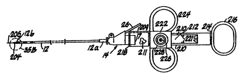
15 Referring now to FIGS. 34-36, there is depicted a
needle-knife assembly 200 adapted for use with the
multi-lumen=catheter 12 shown in FIGS. 1, 9A, 9B and 10.
The needle-knife assembly 200 is principally comprised of
a deployment mechanism 202, and an elongated sheath 204
20 having an elongated connecting tube 205 and needle-knife
206 disposed therein.
The deployment mechanism 202 includes a body 208
having a pair of rails 210 which define a centrally
disposed slot 212. Body 208 includes a first end 214 in
25 which a thumb ring 216 is disposed, and a second end 218
having an end portion 211 at which a fitting 220 is
located for receiving the sheath 204 and connecting tube
205 as described below. A sliding member 222 is slidably
connected to the body 208. The sliding member 222
30 includes a pair of opposed finger rings 224 which enable
a user to grasp the same with -the f oref inger and index
finger. By placing a thumb through thumb ring 216, the
sliding member 222 may be advanced towards the second end
218 of the body 208 to deploy the needle-knife 206, and
35 retracted towards the first end 214 and against stops 221
CA 02220683 1997-11-10
WO 96/35470 PCT/US96/06778
36
to withdraw the needle-knife 206 into the sheath 204 as
described below. A slidable stop 209 is disposed over the
end portion 211 as shown. The sliding stop 209 may be
moved towards and away from the second end 218 to limit
the travel of the sliding member 222 to enable adjustable
positioning of a distal end 213 of the needle-knife 206
relative to a distal end 215 of the sheath 204 by a
variable distance Vd between a fully deployed position
(FIG. 35B) and a sheathed position (FIG. 34). The sliding
member 222 has an internally disposed brass insert 224
which electrically communicates with a brass binding post
226 for making an electrical connection to a power source
(not shown) to provide a cutting/coagulating current as.
is well known in the art. The binding post 226 is
situated within a connector cap 228 integral with sliding
member 222.
As shown in FIG. 36, the elongated connecting tube
205 is attached to and electrically communicates with the
insert 224. The connecting tube 205 is fabricated from
stainless steel and extends through the fitting 220 in
the second end 218 of the mechanism body 208 and
terminates in a distal end 230. The connecting tube 205
has a hollow bore (not shown) into which the needle-knife
206 is partially disposed near distal end 230. The
connecting tube 205 is then crimped over the needle-knife
206 at location 234 as shown in FIG. 36. The fitting
220 tightly receives the elongated tubular sheath 204 and
provides strain relief therefor. In a preferred
embodiment, the sheath 204 is made from polyimide
material with a Teflon coating. This enables fabrication
of a sheath 204 with an outer diameter as small as
approximately .035 inches, to enable advancing the same
through one lumen of the dual lumen catheter 12 used in
an ERCP procedure in accordance with the present
invention. The use of polyimide material provides good
CA 02220683 1997-11-10
WO 96/35470 PCT1CTS96/06778
37
kink resistance, even if the sheath is fabricated with a
very thin wall thickness, and the Teflon coating provides
a smooth surface to enable the sheath 204 to be easily
inserted and removed from the catheter 12. FIG. 35B
shows the orientation of the connecting tube 204 disposed
within the catheter 12, where the distal end 232 of the
sheath 204 extends a nominal distance from the distal end
12b of the catheter 12.
In the preferred embodiment, the needle-knife 206
has a diameter of approximately .006 inches, and is
fabricated from a "memory" metal alloy such as Nitonil.
As is known in the art, memory metals undergo a
crystalline phase change and thermoelastically deform
when heated and cooled. These crystal phase changes
between what are known as high temperature Austenite and
low temperature Martensite, enable a component made from
such material to contract when heated, and to return to
its original configuration when cooled. Moreover, the
stress-strain behavior of a memory metal alloy makes the
material much easier to deform when cooled (Martensite)
than when at an elevated temperature (Austenite) . In the
present invention, the use of this material is
advantageous since the needle-knife 206 is very thin and
susceptible to deformation during the cutting procedure.
The memory material helps it return to its original
orientation if deformed by stress during the cutting
procedure. When the needle-knife 204 is heated by
applying the cutting/coagulating current, the crystalline
transformation to Austenite makes it much more difficult
to deform. If a sufficient force is then applied to the
needle-knife 206 during the procedure, the material can
strain to relieve the applied stress as it transforms
back to Martensite, and once the stress is reduced, it
will unstrain and revert back to Austenite. Finally,
after the applied current is removed, the resulting
CA 02220683 1997-11-10
WO 96/35470 PCT/US96/06778
38
cooling of the needle-knife material and associated
crystal phase change to Martensite makes it more
flexible.
Referring now to FIGS. 34, 35A and 35B, the
needle-knife 206 is disposed so as to remain in a
sheathed position within sheath 204 with respect to the
distal end 232 thereof. The sheath 204 is inserted
through lumen 32 of catheter 12 so that the distal end
232 of the sheath protrudes slightly beyond the distal
end 12b of the catheter 12. The catheter assembly (of
the type shown in FIG. 1) is attached to the deployment
mechanism 202 by threading the luer lock hub 17 of the
connector 14 into the insert 220 at the second end 218 of
the deployment mechanism 202.
Preferably, the needle-knife assembly 200 is
pre-loaded in the catheter 12. This facilitates the use
of the needle-knife assembly in a typical ERCP procedure
using a multi-lumen catheter. In this method, the
physician advances the catheter 12 through an endoscope
(as shown in FIG. 4) and into the patient's duodenum
proximal to the entrance to the common bile duct 40,
typically into or just above the papillary orifice. By
grasping the deployment mechanism 202 by finger rings 224
and thumb ring 216, the physician then advances the
sliding member 222 towards the second end 218 of the
deployment mechanism 202 to cause the needle-knife 206 to
extend from the distal end of the sheath 204 as shown in
FIGS. 35A and 35B. As described above, the slidable stop
209 may be moved over the end portion 211 to custom
position the needle-knife 206 with the distal end 213
thereof at a desired distance Vd relative to the distal
end 215 of the sheath 204 prior to moving the sliding
member 222 towards the second end 218. The physician
applies an appropriate amount of cutting/coagulating
current to the needle-knife 206 through the binding post
CA 02220683 1997-11-10
WO 96/35470 PCT/1JS96/06778
39
226, and manipulates the needle-knife by using the
elevator and/or positioning controls of the endoscope to
incise tissue. Typically, a 3-5 millimeter across by 2-4
millimeter deep incision into the papilla is sufficient.
The needle-knife 206 is then retracted into the distal
end 232 of the sheath 204 by moving the sliding member
222 rearwardly towards the first end 214 and against the
stops 221 of the deployment mechanism 202. This enables
the physician to insert the catheter 12 into the common
bile duct with less effort. Once access is gained to
the common bile duct, the physician can then cannulate
and visualize the same in accordance with the ERCP
procedure described in the foregoing. The sheath 204 and
needle-knife 206 can be left within the first lumen 32 of
the catheter 12 to function as a stiffening element to
enable advancing the catheter into the common bile duct
40 (see FIG. 4), or the sheath 204 and needle-knife 206
may be withdrawn from the catheter 12, and a wire guide
24 then inserted in its place by simply unthreading the
luer lock hub 17 from deployment mechanism 202 and
attaching a wire guide feeding apparatus 27 as shown in
FIG. 7 and described above. The common bile duct 40 can
then be visualized by infusing a contrast medium through
lumen 34. To facilitate further cannulation and/or
visualization of the common bile or other ducts, the wire
guide 24 may be advanced along the duct and the catheter
12 then repositioned by advancing the catheter 12 over
the wire guide to the appropriate location, and the
infusion procedure may be repeated.
This method saves a considerable amount of time over
prior art procedures where cutting instruments had to be
removed prior to infusing the contrast medium. By
keeping the needle-knife assembly 200 in place, the
physician can perform several diagnostic and therapeutic
procedures with only one cannulation of the common bile
CA 02220683 1997-11-10
WO 96/35470 PCT/US96/06778
duct.
The present invention has been described with
reference to the attached Figures and described
embodiments. It is to be appreciated that other
5 embodiments may fulfill the spirit and scope of the
present invention and that the true nature and scope of
the present invention is to be determined with reference
to the claims appended hereto.