Language selection

Search

Patent 2220796 Summary

Third-party information liability

Some of the information on this Web page has been provided by external sources. The Government of Canada is not responsible for the accuracy, reliability or currency of the information supplied by external sources. Users wishing to rely upon this information should consult directly with the source of the information. Content provided by external sources is not subject to official languages, privacy and accessibility requirements.

Claims and Abstract availability

Any discrepancies in the text and image of the Claims and Abstract are due to differing posting times. Text of the Claims and Abstract are posted:

  • At the time the application is open to public inspection;
  • At the time of issue of the patent (grant).
(12) Patent: (11) CA 2220796
(54) English Title: METHOD OF MANUFACTURING A DISC BRAKE BACKING PLATE WITH AN EDGE HOLE
(54) French Title: METHODE DE FABRICATION DE PLATEAUX DE FREINS A DISQUE MUNIS D'ORIFICES EN ANGLE
Status: Expired
Bibliographic Data
(51) International Patent Classification (IPC):
  • B21K 7/14 (2006.01)
  • B21K 1/00 (2006.01)
  • B21K 1/76 (2006.01)
  • F16D 65/092 (2006.01)
(72) Inventors :
  • ARBESMAN, RAY (Canada)
(73) Owners :
  • NUCAP INDUSTRIES INC. (Canada)
(71) Applicants :
  • ARBESMAN, RAY (Canada)
(74) Agent: BERESKIN & PARR LLP/S.E.N.C.R.L.,S.R.L.
(74) Associate agent:
(45) Issued: 2002-07-02
(22) Filed Date: 1997-11-12
(41) Open to Public Inspection: 1999-05-12
Examination requested: 1997-11-12
Availability of licence: N/A
(25) Language of filing: English

Patent Cooperation Treaty (PCT): No

(30) Application Priority Data: None

Abstracts

English Abstract

A method of manufacturing a disc brake backing plate with an edge hole which comprises the steps of first forming two substantially parallel grooves on the outer surface of the backing plate to define a raised section between the grooves. A channel is then formed within the raised section to define two ridges bounding the channel. Finally, the ridges are bent toward each other to define the hole.


French Abstract

Un procédé de fabrication d'une plaque de support de frein à disque avec un trou de bord qui comprend les étapes consistant à former tout d'abord deux rainures sensiblement parallèles sur la surface extérieure de la plaque de support pour définir une partie surélevée entre les rainures. Un canal est ensuite formé dans la section surélevée afin de définir deux nervures délimitant le canal. Enfin, les nervures sont courbées l'une vers l'autre pour définir l'orifice.

Claims

Note: Claims are shown in the official language in which they were submitted.


THE EMBODIMENTS OF THE INVENTION IN WHICH AN EXCLUSIVE PROPERTY
OR PRIVILEGE IS CLAIMED ARE DEFINED AS FOLLOWS:
1. A method of manufacturing a disc brake backing plate with an edge hole
comprising the steps of:
a) forming two substantially parallel grooves on the surface said backing
plate to define a rounded raised section running between said grooves;
b) forming a channel within said rounded raised section to define two
substantially parallel ridges bounding said channel; and
c) bending said ridges toward each other to define an edge hole.
2. A method of manufacturing a disc brake backing plate as defined in claim 1,
wherein said grooves and said raised section are cold-formed by punching said
backing plate with a first punching tool comprising a distal end.
3. A method of manufacturing a disc brake backing plate as defined in claim 2,
wherein the distal end of said first punching tool comprises a rounded
depression bounded by two substantially parallel projections to form said
grooves and said raised section upon impact with said backing plate.
4. A method of manufacturing a disc brake as defined in claim 1, wherein said
channel and said ridges are cold-formed by punching said projection with a
second punching tool comprising a distal end.
5. A method of manufacturing a disc brake backing plate as defined in claim 4,
wherein the distal end of said second punching tool has a convex surface to
form said channel and said ridges upon impact with said raised section, said
channel having a substantially semi-circular cross-section to correspond with
said convex surface of said punching tool.


6. A method of manufacturing a disc brake backing plate as defined in claim 1,
wherein said ridges are bent to define said hole by punching said ridges with
a
third punching tool comprising a distal end.
7. A method of manufacturing a disc brake backing plate as defined in claim 6,
wherein the distal end of said third punching tool has a concave surface to
bend said ridges toward each other upon impact with said ridges to form a
substantially circular hole.
6

Description

Note: Descriptions are shown in the official language in which they were submitted.


CA 02220796 1997-11-12


Title: METHOD OF MANUFACTURING A DISC BRAKE BACKING PLATE WITH
AN EDGE HOLE
Inventor: Ray Arl,es,.,an


5 FIELD OF THE INVENTION


The present invention relates to disc brakes for automobiles, and in
particular, to a method of manufacturing a disc brake backing plate with a hole located
within an edge of the backing plate.
In manufacturing a backing plate, it is customary to place a backing plate pre-

10 form on an assembly line where tools with different punching and stamping surfaces willshape its contact surface to produce features such as holes or knobs to assist in attaching
and retaining a friction pad. However, an additional hole within the edge of the backing
plate parallel to the surface may be required, for example, to retain a conventional anti-rattle
spring.

BACKGROUND OF THE INVENTION
Prior art methods for manufacturing a backing plate with an edge hole have required the
backing plate to be removed from the assembly line and for the hole to be drilled by hand,
requiring additional labor, creating delays and adding costs. In addition, drilling a hole within
20 the edge may introduce structural weaknesses into the backing plate leading to cracking
and other modes of structural failure.


SUMMARY OF THE INVENTION
The present invention overcomes these deficiencies of the prior art by
25 providing a method for manufacturing a disc brake backing plate with an edge hole by

preferably punching the-hole into the backing plate as it moves along an assembly line,


CA 02220796 1997-11-12


without requiring manual labor to remove the backing plate and drill the hole. The improved
method provides significant cost savings by eliminating the manual labor required to drill the
hole and reducing the time for manufacturing the backing plate.
The present invention comprises a method whereby two preferably parallel
grooves are formed within the outer surface of the backing plate to define a rounded raised
section running between the grooves. Preferably, a generally semi-circular channel is then
formed in the raised section to define two generally parallel ridges bounding the channel.
Finally, the ridges are bent toward each other to define a preferably generally circular edge
hole
With the above and other objects in view, more information and a better
understanding of the invention will be achieved by referring to the following description.

BRIEF DESCRIPTION OF THE DRAWINGS
The present invention, as exemplified by a preferred embodiment, is
described with reference to the drawings in which:
FIG. 1 is a perspective view of the disc brake backing plate before application
of the method;
FIG. 2 is a cross-sectional view showing the first step in the method of
manufacturing the backing plate with the edge hole;
FIG. 3 is a cross-sectional view showing the second step in the method of
manufacturing the backing plate with the edge hole;
FIG. 4 is a cross-sectional view showing the third step in the method of
manufacturing the backing plate with the edge hole;
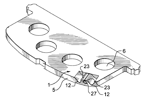
FIG. 5 is a perspective view showing the backing plate with the edge hole
manufactured by the method;

CA 02220796 1997-11-12


FIG. 6 is a top view of the backing plate with the edge hole manufactured by
the method; and
FIG. 7 is an elevation view of the backing plate with edge hole manufactured
by the method.


DESCRIPTION OF THE PREFERRED EMBODIMENT
Fig 1 shows a generally flat backing plate 1, preferably stamped from a single
piece of steel, having a contact surface 2 to which a friction pad (not shown) is attached, a
10 parallel outer surface 4, and an edge 5. A plurality of holes 6 penetrate the backing plate
configured to retain the friction pad .

As shown in Fig. 2, the backing plate 1 is positioned on a rigid platform 10,
which forms part of an assembly line. Fig. 2 also shows the first step of the process, where,
preferably, a first punching tool 11 punches the outer surface 4 of the backing plate to form
15 two generally parallel grooves 12. The material between the grooves is displaced by the
impact to form a rounded raised section 13 between the grooves. The impact surface of the
first punching tool preferably comprises two rounded vertical projections 15 extending
downwardly on either side of a depression 16.
The backing plate 1 then moves along the assembly line to the second step
20 in the process, as shown in Fig. 3. A second punching tool 20 having a convex surface at
its distal end 21 punches the raised section 13 of the backing plate to form a preferably
semi-circular channel 22 and two upwardly extending ridges 23 bounding the channel.
Fig. 4 shows the final step in the process, where a third punching tool 25
having a concave surface at its distal end 26 impacts downwardly on the two ridges with
25 sufficient force to cause them to bend toward each other, and, together with the semi-
circular channel, to form a preferably circular edge hole 27.


CA 02220796 1997-11-12


The edge hole produced according to the method of the present invention, as
best seen in Figs. 5-7, can be used in a number of ways in a disc brake assembly, such as,
for example, to retain a conventional anti-rattle spring (not shown).
The present invention has been described in detail and with particular
5 reference to the preferred embodiments; however, it will be understood that modifications to
the present invention could be made by one skilled in the art without departing or deviating
from the spirit or scope of the invention herein described.


Representative Drawing
A single figure which represents the drawing illustrating the invention.
Administrative Status

For a clearer understanding of the status of the application/patent presented on this page, the site Disclaimer , as well as the definitions for Patent , Administrative Status , Maintenance Fee  and Payment History  should be consulted.

Administrative Status

Title Date
Forecasted Issue Date 2002-07-02
(22) Filed 1997-11-12
Examination Requested 1997-11-12
(41) Open to Public Inspection 1999-05-12
(45) Issued 2002-07-02
Expired 2017-11-14

Abandonment History

There is no abandonment history.

Payment History

Fee Type Anniversary Year Due Date Amount Paid Paid Date
Request for Examination $400.00 1997-11-12
Application Fee $300.00 1997-11-12
Maintenance Fee - Application - New Act 2 1999-11-12 $100.00 1999-11-12
Maintenance Fee - Application - New Act 3 2000-11-13 $100.00 2000-09-27
Maintenance Fee - Application - New Act 4 2001-11-12 $100.00 2001-10-12
Final Fee $300.00 2002-04-22
Maintenance Fee - Patent - New Act 5 2002-11-12 $150.00 2002-09-27
Maintenance Fee - Patent - New Act 6 2003-11-12 $150.00 2003-09-18
Maintenance Fee - Patent - New Act 7 2004-11-12 $200.00 2004-11-12
Maintenance Fee - Patent - New Act 8 2005-11-14 $200.00 2005-11-14
Maintenance Fee - Patent - New Act 9 2006-11-13 $200.00 2006-10-17
Maintenance Fee - Patent - New Act 10 2007-11-12 $250.00 2007-10-24
Maintenance Fee - Patent - New Act 11 2008-11-12 $250.00 2008-10-27
Registration of a document - section 124 $100.00 2009-01-09
Maintenance Fee - Patent - New Act 12 2009-11-12 $250.00 2009-11-05
Registration of a document - section 124 $100.00 2009-11-25
Maintenance Fee - Patent - New Act 13 2010-11-12 $250.00 2010-11-12
Registration of a document - section 124 $100.00 2010-12-08
Maintenance Fee - Patent - New Act 14 2011-11-14 $250.00 2011-10-12
Maintenance Fee - Patent - New Act 15 2012-11-13 $450.00 2012-11-01
Maintenance Fee - Patent - New Act 16 2013-11-12 $450.00 2013-11-01
Maintenance Fee - Patent - New Act 17 2014-11-12 $450.00 2014-11-03
Maintenance Fee - Patent - New Act 18 2015-11-12 $450.00 2015-10-21
Maintenance Fee - Patent - New Act 19 2016-11-14 $450.00 2016-10-11
Registration of a document - section 124 $100.00 2017-09-14
Owners on Record

Note: Records showing the ownership history in alphabetical order.

Current Owners on Record
NUCAP INDUSTRIES INC.
Past Owners on Record
ARBESMAN, RAY
Past Owners that do not appear in the "Owners on Record" listing will appear in other documentation within the application.
Documents

To view selected files, please enter reCAPTCHA code :


To view images, click a link in the Document Description column. To download the documents, select one or more checkboxes in the first column and then click the "Download Selected in PDF format (Zip Archive)" or the "Download Selected as Single PDF" button.

List of published and non-published patent-specific documents on the CPD .

If you have any difficulty accessing content, you can call the Client Service Centre at 1-866-997-1936 or send them an e-mail at CIPO Client Service Centre.


Document
Description 
Date
(yyyy-mm-dd) 
Number of pages   Size of Image (KB) 
Cover Page 1999-05-21 1 29
Representative Drawing 2002-05-29 1 13
Claims 2000-09-15 2 56
Cover Page 2002-05-29 1 34
Abstract 1997-11-12 1 10
Description 1997-11-12 4 116
Claims 1997-11-12 2 45
Drawings 1997-11-12 3 66
Representative Drawing 1999-05-21 1 8
Assignment 2009-11-25 14 1,108
Assignment 1997-11-12 2 76
Correspondence 1999-10-26 1 29
Assignment 1997-11-12 3 104
Prosecution-Amendment 2000-05-25 2 36
Prosecution-Amendment 2000-09-15 4 135
Fees 2000-09-27 1 34
Fees 1999-11-12 1 41
Fees 2003-09-18 1 35
Correspondence 2002-04-22 1 35
Fees 2001-10-12 1 35
Fees 2002-09-27 1 34
Fees 2004-11-12 1 36
Fees 2005-11-14 1 34
Fees 2006-10-17 1 32
Fees 2007-10-24 1 34
Fees 2008-10-27 1 34
Assignment 2009-01-09 12 602
Fees 2009-11-05 1 39
Fees 2010-11-12 1 38
Assignment 2010-12-08 14 896
Fees 2011-10-12 1 37
Fees 2012-11-01 1 39
Fees 2014-11-03 1 38
Fees 2013-11-01 1 39
Correspondence 2015-08-06 4 141
Office Letter 2015-08-24 2 152
Office Letter 2015-08-24 2 185