Language selection

Search

Patent 2220814 Summary

Third-party information liability

Some of the information on this Web page has been provided by external sources. The Government of Canada is not responsible for the accuracy, reliability or currency of the information supplied by external sources. Users wishing to rely upon this information should consult directly with the source of the information. Content provided by external sources is not subject to official languages, privacy and accessibility requirements.

Claims and Abstract availability

Any discrepancies in the text and image of the Claims and Abstract are due to differing posting times. Text of the Claims and Abstract are posted:

  • At the time the application is open to public inspection;
  • At the time of issue of the patent (grant).
(12) Patent: (11) CA 2220814
(54) English Title: A MECHANICAL SEAL
(54) French Title: JOINT MECANIQUE
Status: Expired
Bibliographic Data
(51) International Patent Classification (IPC):
  • F16J 15/54 (2006.01)
  • F01D 11/00 (2006.01)
  • F04D 29/08 (2006.01)
  • F16J 15/00 (2006.01)
  • F16J 15/34 (2006.01)
(72) Inventors :
  • FONDELIUS, JOHAN (Sweden)
(73) Owners :
  • ITT MANUFACTURING ENTERPRISES, INC. (United States of America)
(71) Applicants :
  • ITT MANUFACTURING ENTERPRISES, INC. (United States of America)
(74) Agent: SMART & BIGGAR
(74) Associate agent:
(45) Issued: 2002-01-01
(22) Filed Date: 1997-11-13
(41) Open to Public Inspection: 1998-05-14
Examination requested: 1997-11-13
Availability of licence: N/A
(25) Language of filing: English

Patent Cooperation Treaty (PCT): No

(30) Application Priority Data:
Application No. Country/Territory Date
9604158-7 Sweden 1996-11-14

Abstracts

English Abstract


The invention concerns a mechanical face seal being a part of a seal arrangementfor a submersible machine such as a pump or a mixer.

In order to secure that liquid that may have penetrated the seal adjacent the driving
unit of the machine to cause damage, the seal is designed as a pumping seal which
immediately returns said liquid.


French Abstract

Cette invention concerne un joint mécanique faisant partie d'une structure de joint de machine immersible comme une pompe ou un mélangeur. Pour retenir ce liquide, qui pourrait provoquer des dégâts en traversant le joint contigu à l'unité d'entraînement de la machine, ce joint est conçu comme un dispositif de pompage qui renvoie immédiatement le liquide en question vers son point de départ.

Claims

Note: Claims are shown in the official language in which they were submitted.


5
CLAIMS:
1. A seal system for a submersible machine which
comprises an electric motor/generator and a hydraulic unit,
said seal system comprising two seals and an intermediate
barrier liquid room adapted to contain a liquid, wherein at
least one of the seals is a mechanical face seal, and the
other of said two seals is adjacent the electric
motor/generator, interposed between air and liquid contained
in said intermediate barrier liquid room, adapted to prevent
the liquid in the barrier liquid room from penetrating to the
atmosphere in the electric motor/generator, and is a pumping
seal having at least one of two seal surfaces that face each
other designed with a pressure building geometry which
repumps possible leakage of barrier liquid through the seal
back to the barrier liquid room.
2. A seal system according to claim 1, characterized
in that the pressure building geometry is constituted by a
number of shallow and swept grooves, which extend over a part
of the seal surface and leave an annular formed unbroken seal
surface adjacent the barrier liquid side.
3. A sealing arrangement for a pump including an
electric motor/generator and a pump housing, said sealing
arrangement comprising:
an intermediate barrier liquid chamber;
a mechanical face seal interposed between said pump
housing and said intermediate barrier liquid chamber; and,
a pumping seal interposed between said intermediate
barrier liquid chamber and said electric motor/generator such
that air is on a first side thereof and liquid contained in


6
said intermediate barrier liquid chamber is on an oppositely
disposed second side thereof;
wherein said pumping seal is adapted to repump
leakage of said liquid from said first side to said second
side of said pumping seal.

Description

Note: Descriptions are shown in the official language in which they were submitted.


CA 02220814 1997-11-13
1
J. Fondelius - 5
A mechanical seal
The invention concerns a mechanical seal being a part of a seal arrangement
for a
submersible machine such as a pump or a mixer.
A machine of this type normally comprises an electric motor and a hydraulic
unit
having a rotary impeller connected to the motor via a rotary shaft.
In order to prevent the medium within the hydraulic unit from entering along
the shaft
into the electric motor and damage it, one or several seals are arranged
between the
hydraulic unit and the electric motor. One common type of seal is here the so-
called
mechanical face seal which consists of one seal ring rotating with the driving
shaft
and one stationary seal ring attached to the surrounding housing. The two seal
rings
are pressed towards each other by spring force and prevent in this way liquid
from
passing between them.
It is however essential that a thin lubricating film is always established
between the
seal surfaces. This is necessary to prevent the seals from being damaged by
dry
friction. The consequence is however, that the necessary slot between the two
seal
surfaces is subject to a certain leakage. This leakage can normally be
neglected and
is harmless, but sometimes wear, vibrations or a wrong mounting may cause an
increased leakage.
If the medium within the hydraulic unit contains contaminations, these may
penetrate
into the slot between the seal surfaces and cause damage which means that the
sealing result is destroied. It is therefore common to arrange two mechanical
seals
parted by a room filled by a barrier liquid such as oil. This means that the
seal
adjacent the electric motor, here called the inner seal, always operates with
a clean
medium, thus diminishing the risks for damages or the seal surfaces. If the
seal


72432-107 ca o222osi4 Zooo-io-o2
2
adjacent the hydraulic unit, here called the outer seal,
should be damaged, medium from the hydraulic unit could
penetrate into the barrier liquid, but by checking the
quality of said liquid at even intervals, the seal can be
repaired before the liquid has been diluted too much. An
example of this is shown in the Swedish Patent No. 366 013.
In order to obtain a seal that is entirely free
from leakage it is known to use a so-called pumping seal as
the outer seal. Barrier liquid is then pumped out into the
hydraulic unit which means that any leakage from the
hydraulic unit is prevented. This could be a good solution,
but a disadvantage is that barrier liquid must be fed
constantly. In addition there is a certain risk that said
liquid also could pass the inner seal and cause damage to the
electric motor.
The invention may be summarized as a seal system
for a submersible machine which comprises an electric
motor/generator and a hydraulic unit, said seal system
comprising two seals and an intermediate barrier liquid room
adapted to contain a liquid, wherein at least one of the
seals is a mechanical face seal, and the other of said two
seals is adjacent the electric motor/generator, interposed
between air and liquid contained in said intermediate barrier
liquid room, adapted to prevent the liquid in the barrier
liquid room from penetrating to the atmosphere in the
electric motor/generator, and is a pumping seal having at
least one of two seal surfaces that face each other designed
with a pressure building geometry which repumps possible
leakage of barrier liquid through the seal back to the
barrier liquid room.


72432-107 CA o222osi4 2ooo-io-o2
3
According to another aspect the invention provides
a sealing arrangement for a pump including an electric
motor/generator and a pump housing, said sealing arrangement
comprising: an intermediate barrier liquid chamber; a
mechanical face seal interposed between said pump housing and
said intermediate barrier liquid chamber; and, a pumping seal
interposed between said intermediate barrier liquid chamber
and said electric motor/generator such that air is on a first
side thereof and liquid contained in said intermediate
barrier liquid chamber is on an oppositely disposed second
side thereof; wherein said pumping seal is adapted to repump
leakage of said liquid from said first side to said second
side of said pumping seal.
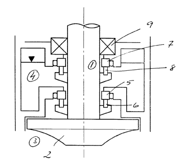
The invention is described more closely below with
reference to the enclosed drawing which schematically shows a
mechanical face seal system according to the invention.
In the drawing 1 stands for a driving shaft between
a motor, not shown, and a pump impeller 2 rotating in a pump
housing or hydraulic unit 3. 4 stands for a barrier liquid
housing 5,6, an outer seal 7,8, an inner seal 9 and a
bearing.
The purpose of the outer seal 5,6 is thus to
prevent pumped medium within the pump housing 3 from entering
the barrier liquid housing 4, while the inner seal 7,8 in a
corresponding way is meant to prevent the barrier liquid
within the housing 4 from entering the motor capsule via the
driving shaft.
In order to secure that liquid will not penetrate
into the motor if the inner seal 7,8 should leak more than
expected, the inner seal 7,8 is designed in a special way as
will be described below such that an entirely leakage free


72432-107 CA o222osi4 2ooo-io-o2
4
sealing is obtained without the need for any feeding of
barrier liquid.
This is obtained by designing the outer seal 5,6
between the hydraulic unit 3 and the barrier liquid housing 4
like a conventional seal, while the inner seal 7,8 between
the barrier liquid housing 4 and the motor is designed like a
pumping seal. The seal 7,8 which operates with air on its
one side and liquid, the barrier liquid on its other side, is
designed with pressure building grooves (not shown) on the
seal surface. These grooves start at the air side of the
seal and extend inwards in the direction of the liquid side
of the seal, however without reaching the liquid side. This
creates an unbroken sealing circle adjacent the barrier
liquid side which in the normal case acts as a conventional
mechanical face seal. If liquid should penetrate to the air
side of the seal, the grooves in the seal surface will
immediately start pumping back the liquid into the barrier
liquid housing, before the leaking liquid has caused any
damage.
The invention is thus characterized by the
arrangement of a pumping mechanical face seal being
positioned between a room containing a liquid and a room
containing air. The pumping seal may be designed in
different ways. Examples are shown in the Swedish Patent No.
960 816-8 and the European Patent No. 564 153. Both seal
surfaces are provided with shallow grooves which obtain the
pumping, while an unbroken seal surface obtains the sealing.

Representative Drawing
A single figure which represents the drawing illustrating the invention.
Administrative Status

For a clearer understanding of the status of the application/patent presented on this page, the site Disclaimer , as well as the definitions for Patent , Administrative Status , Maintenance Fee  and Payment History  should be consulted.

Administrative Status

Title Date
Forecasted Issue Date 2002-01-01
(22) Filed 1997-11-13
Examination Requested 1997-11-13
(41) Open to Public Inspection 1998-05-14
(45) Issued 2002-01-01
Expired 2017-11-14

Abandonment History

There is no abandonment history.

Payment History

Fee Type Anniversary Year Due Date Amount Paid Paid Date
Request for Examination $400.00 1997-11-13
Registration of a document - section 124 $100.00 1997-11-13
Application Fee $300.00 1997-11-13
Maintenance Fee - Application - New Act 2 1999-11-15 $100.00 1999-10-20
Maintenance Fee - Application - New Act 3 2000-11-13 $100.00 2000-10-17
Final Fee $300.00 2001-10-01
Maintenance Fee - Application - New Act 4 2001-11-13 $100.00 2001-10-15
Maintenance Fee - Patent - New Act 5 2002-11-13 $150.00 2002-11-08
Maintenance Fee - Patent - New Act 6 2003-11-13 $150.00 2003-07-30
Maintenance Fee - Patent - New Act 7 2004-11-15 $200.00 2004-10-19
Maintenance Fee - Patent - New Act 8 2005-11-14 $200.00 2005-11-04
Maintenance Fee - Patent - New Act 9 2006-11-13 $200.00 2006-10-18
Maintenance Fee - Patent - New Act 10 2007-11-13 $250.00 2007-10-16
Maintenance Fee - Patent - New Act 11 2008-11-13 $250.00 2008-10-29
Maintenance Fee - Patent - New Act 12 2009-11-13 $250.00 2009-10-30
Maintenance Fee - Patent - New Act 13 2010-11-15 $250.00 2010-10-18
Maintenance Fee - Patent - New Act 14 2011-11-14 $250.00 2011-10-17
Maintenance Fee - Patent - New Act 15 2012-11-13 $450.00 2012-10-17
Maintenance Fee - Patent - New Act 16 2013-11-13 $450.00 2013-10-17
Maintenance Fee - Patent - New Act 17 2014-11-13 $450.00 2014-11-10
Maintenance Fee - Patent - New Act 18 2015-11-13 $450.00 2015-11-09
Maintenance Fee - Patent - New Act 19 2016-11-14 $450.00 2016-11-07
Owners on Record

Note: Records showing the ownership history in alphabetical order.

Current Owners on Record
ITT MANUFACTURING ENTERPRISES, INC.
Past Owners on Record
FONDELIUS, JOHAN
Past Owners that do not appear in the "Owners on Record" listing will appear in other documentation within the application.
Documents

To view selected files, please enter reCAPTCHA code :


To view images, click a link in the Document Description column. To download the documents, select one or more checkboxes in the first column and then click the "Download Selected in PDF format (Zip Archive)" or the "Download Selected as Single PDF" button.

List of published and non-published patent-specific documents on the CPD .

If you have any difficulty accessing content, you can call the Client Service Centre at 1-866-997-1936 or send them an e-mail at CIPO Client Service Centre.


Document
Description 
Date
(yyyy-mm-dd) 
Number of pages   Size of Image (KB) 
Abstract 1997-11-13 1 10
Drawings 1997-11-13 1 10
Description 1997-11-13 3 118
Claims 1997-11-13 1 28
Cover Page 2001-11-29 1 30
Representative Drawing 1998-06-02 1 6
Representative Drawing 2001-11-29 1 7
Description 2000-10-02 4 169
Claims 2000-10-02 2 52
Cover Page 1998-06-02 1 31
Correspondence 2001-10-01 1 41
Assignment 1997-11-13 5 193
Prosecution-Amendment 2000-08-08 1 24
Prosecution-Amendment 2000-10-02 7 235