Note: Descriptions are shown in the official language in which they were submitted.
CA 02220919 2000-OS-17
Field of the Invention
The present invention relates to a control valve. More particularly, the
present
invention relates to a dual poppet fluid control valve which, when an abnormal
situation is encountered, the control valve moves to a locked out position
which in one
embodiment requires a resetting operation before the control valve will again
function
and in another embodiment, the control valve automatically resets.
Background and Summar~r of the Invention
Machine tools of various types operate through a valuing system which
interacts with a pneumatic controlled clutch and/or brake assembly. For safety
reasons, the control valves which are used to operate these machine tools
require the
operator to actuate two separate control signal applying contacts essentially
simultaneously. This requirement of simultaneous application ensures that the
operator will not have his hand near the moving components of the machine tool
when an operating cycle is initiated. The two control signal applying contacts
can
then be connected to the valuing system which allows compressed air to be
delivered
to the machine tool to perform its operating cycle.
Safety rules and regulations require the valuing system to be designed such
that if a component in the valuing system malfunctions, the valuing system
will not
allow additional movement of the machine tool. In addition, the valuing system
must
2o ensure that a new operation cycle of the machine tool cannot be initiated
after a
component of the valuing system has become defective.
Prior art electromagnetic valuing systems which are utilized for the operation
of machine tools meet these safety requirements through the use of a double
valve
assembly. The double valve assembly, includes two electromagnetic supply
valves
which are normally closed. Each of the supply valves is moved to an open
position
in response to an electrical control signal. The two supply valves are
arranged in
series with respect to the source of compressed air. The double valve assembly
also
includes two exhaust valves which are normally open. Each exhaust valve is
closed
' CA 02220919 1997-11-12
-2-
by a respective supply valve when it is opened. It is therefore necessary for
the
supply valves to be opened simultaneously otherwise, supply air will be
exhausted
from the system through one of the exhaust valves. The opening and closing of
the
valve units is monitored by sensing air pressures in the respective valve
units and
then compare these two pressures. The monitoring and comparing of these two
pressures is accomplished by using a single air cylinder which is separated
into two
chambers by a piston. The pressure in each valve unit is delivered to one of
the
chambers. Thus, unequal pressures in the valve units will cause movement of
the
normally static piston which will then interrupt the electrical signal to one
of the valve
units. This and other external electronic monitoring arrangements are
expensive and
require that electrical signal processing equipment be designed and utilized.
The continued development of the valuing systems for machine tools has been
directed toward more reliable, simpler and less costly valuing systems which
both
meet and exceed the safety performance requirements in force today as well as
those
proposed for the future.
The present invention provides the art with a control valve system which
operates entirely pneumatically thus eliminating the need for electrical
monitoring and
the associated controls. The control valve system includes a plurality of
valves each
of which open or close during the actuation or deactuation of the valves. The
control
valve system monitors the dynamic movement of the various valves of the system
to
ensure the proper functioning of the control valve system. In one embodiment,
the
control valve system moves to a locked out position upon sensing a malfunction
and
remains in this locked out position until a resetting operation is pertormed.
In another
embodiment, the control valve system moves to a locked out position upon
sensing
a malfunction and then automatically resets after a period of time. Thus, the
operation of the control assembly is totally dynamic and the system does not
rely on
the monitoring of a static member to ensure its proper function.
Other advantages and objects of the present invention will become apparent
to those skilled in the art from the subsequent detailed description, appended
claims
and drawings.
Brief Description of the Drawings
In the drawings which illustrate the best mode presently contemplated for
carrying out the present invention:
~
CA 02220919 1997-11-12
-3-
Figure 1 is a schematic circuit diagram of the control valve system of the
present invention shown in a deactuated position;
Figure 2 is a schematic illustration of the control valve shown in its
deactuated
position;
Figure 8 is a schematic circuit diagram of the control valve system of the
present invention shown in an actuated position;
Figure 4 is a schematic illustration of the control valve shown in Figure 1 in
its
actuated position;
Figure 8 is a schematic circuit diagram of the control valve system of the
present invention shown in an abnormal position;
Figure 6 is a schematic illustration of the control valve shown in Figure 1 in
its
abnormal position;
Figure 7 is a schematic circuit diagram of the control valve system of the
present invention shown in a locked out position;
Figure 8 is a schematic illustration of the control valve shown in Figure 1 in
its
locked out position;
Figure 9 is a schematic illustration of the valuing system shown in Figures 1-
8
in accordance with another embodiment of the present invention.
Figure 10 is a schematic illustration of a control valve in accordance with
another embodiment of the present invention shown in its deactuated position;
Figure 11 is a schematic illustration of the control valve shown in Figure 10
in
its actuated position;
Figure 12 is a schematic illustration of the control valve shown in Figure 10
in
its abnormal position;
Figure 13 is a schematic illustration of a control valve in accordance with
another embodiment of the present invention shown in its deactuated position;
Figure 1~4 is a schematic illustration of the control valve shown in Figure 13
in
its actuated position; and
Figure 1~ is a schematic illustration of the control valve shown in Figure 13
in
its abnormal position.
CA 02220919 1997-11-12
-4-
Detailed Description of the Preferred Embodiment
'Referring now to the drawings in which like reference numerals designate like
or corresponding parts throughout the several views, there is shown in Figures
1 and
2 a control valve system in accordance with the present invention which is
designated
generally by the reference numeral 10. Control valve system 10 is shown as a
schematic fluid circuit in Figure 1 and as a fluid control valve in Figure 2.
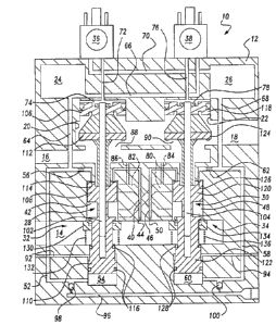
Referring now to Figure 2, control valve system 10 comprises a housing 12
having a fluid inlet passage 14, a fluid outlet passage 16, a fluid exhaust
passage 18,
a first valve bore 20, a second valve bore 22, a first fluid reservoir 24 and
a second
fluid reservoir 26. Disposed within first valve bore 20 is a first valve
member 28 and
disposed within second valve bore 22 is a second valve member 30. Located
within
inlet passage 14 in a coaxial relationship with first valve member 28 is a
third valve
member 32. Also located within inlet passage 14 in a coaxial relationship with
second
valve member 30 is a fourth valve member 34. A pair of solenoid valves 36 and
38
are attached to housing 12.
A plurality of fluid passages interconnect valve bores 20 and 22 with inlet
passage 14, outlet passage 16, exhaust passage 18, reservoir 24, reservoir 26,
valve
36 and valve 38. A fluid passage 40 extends between inlet passage 14 and an
intermediate chamber 42 formed by bore 20. A restrictor 44 is disposed within
passage 40 to limit the amount of fluid flow through passage 40. A fluid
passage 46
extends between inlet passage 14 and an intermediate chamber 48 formed by bore
22. A restrictor 50 is disposed within passage 46 to limit the amount of fluid
flow
through passage 46.
A fluid passage 52 extends between chamber 42 and a lower chamber 54
formed by bore 20. A restrictor 56 is disposed within passage 52 to limit the
amount
of fluid flow through passage 52. A fluid passage 58 extends between chamber
48
and a lower chamber 60 formed by bore 22. A restrictor 62 is disposed within
passage 58 to limit the amount of fluid flow through passage 58. A fluid
passage 64
extends between passage 52 and reservoir 24 such that restrictor 56 is located
between chamber 42 and reservoir 24. A fluid passage 66 extends between
reservoir
24 and the input to solenoid valve 38. A fluid passage 68 extends between
passage
58 and reservoir 26 such that restrictor 62 is located between chamber 48 and
reservoir 24. A fluid passage 70 extends between reservoir 26 and the input to
solenoid valve 36. A passage 72 extends between the output of solenoid valve
36
~
CA 02220919 1997-11-12
-5-
and an upper chamber 74 formed by bore 20. A passage 76 extends between the
output of solenoid valve 38 and an upper chamber 78 formed by bore 22.
A cross passage 80 extends between the lower portion of chamber 42 and the
upper portion of chamber 48. A cross passage 82 extends between the lower
portion
of chamber 48 and the upper portion of chamber 42. A fluid passage 84 extends
between passage 80 and outlet passage 16. A fluid passage 86 extends between
passage 82 and outlet passage 16. Outlet passage 16 is in communication with
exhaust passage 18 through two ports 88 and 90. The upper portions of chambers
54 and 60 are in communication with atmospheric pressure through passages 92
and
94, respectively. A reset passage 96 extends into housing 12 and is in
communication with the lower portion of chambers 54 and 60 by communicating
with
passages 52 and 58, respectively. A pair of check valves 98 and 100 are
disposed
between reset passage 96 and passages 52 and 58 respectively, to prohibit
fluid flow
between passages 52 or 58 to reset passage 96 but allow fluid flow from reset
passage 96 to one or both passages 52 and 58.
Disposed within bore 20 is valve member 102 and disposed within bore 22 is
valve member 104. Valve member 102 comprises an upper piston 106, an
intermediate piston 108 and a lower piston 110 all of which move together as a
single
unit. Upper piston 106 is disposed within chamber 74 and includes a valve seat
112
which opens and closes port 88 located between outlet passage 16 and exhaust
passage 18. Intermediate piston 108 is disposed within chamber 42 and includes
an
annular passage 114 which fluidly connects passage 40 to passage 52 when
piston
108 is seated against housing 12. Lower piston 110 is located within chamber
54 and
includes a pair of seals 116 which seal inlet passage 14 from passage 92 and
seal
chamber 54 from passage 92. Valve member 104 comprises a upper piston 118, an
intermediate piston 120 and a lower piston 122 all of which move together as a
single
unit. Upper piston 118 is disposed within chamber 78 and includes a valve seat
124
which opens and closes port 90 located between outlet passage 16 and exhaust
passage 18. Intermediate piston 120 is disposed within chamber 48 and includes
an
annular passage 126 which fluidly connects passage 46 to passage 58 when
piston
120 is seated against housing 12. Lower piston 122 is located within chamber
60 and
includes a pair of seals 128 which seal inlet passage 14 from passage 94 and
seal
chamber 60 from passage 94.
CA 02220919 1997-11-12
-6-
Valve member 32 is located around lower piston 110 and comprises a valve
seat 130 and a valve spring 132. Valve spring 132 biases valve seat 130
against
housing 12 to prohibit fluid flow between inlet passage 14 and chamber 42.
Valve
member 34 is located around piston 122 and comprises a valve seat 134 and a
valve
spring 136. Valve spring 136 biases valve seat 134 against housing 12 to
prohibit
fluid flow between inlet passage 14 and chamber 48.
Figures 1 and 2 illustrate control valve system 10 in its deactuated position.
Pressurized fluid from inlet
passage 14 is biasing valve seats 130 and 134 against housing 12 closing
communication between inlet passage 14 and both chambers 42 and 48.
Pressurized
fluid is 'provided to passage 40 through restrictor 44, to passage 52 through
annular
passage 114 through restrictor 56 and into chamber 54 to bias valve member 102
upward as shown in Figure 2 seating piston 108 against housing 12. Pressurized
fluid
also flows through passage 52, through passage 64 to reservoir 24 and from
reservoir
24 to the inlet of solenoid valve 38 through passage 66. In a similar manner,
pressurized fluid from inlet passage 14 is provided to passage 46 through
restrictor
50 to passage 58 through annular passage 126 through restrictor 62 and into
chamber 60 to bias valve member 104 upward as shown in Figure 2 seating piston
120 against hausing 12. Pressurized fluid also flows through passage 58,
through
passage 68 to reservoir 26 and from reservoir 26 to the inlet of solenoid
valve 36
through passage 70. Outlet passage 16 is in communication with exhaust passage
18 due to valve seats 112 and 124 being biased upward opening ports 88 and 90.
Intermediate chambers 42 and 48 are also open to exhaust passage 18 through
cross
passages 80 and 82, respectively, through passages 84 and 86, respectively.
The
fluid pressure below piston 110 and 122 of valve members 102 and 104,
respectively,
bias valve members 102 and 104 upward maintaining control valve system 10 in
the
deactuated position. The connection between passages 40 and 52 through annular
passage 114 and the connection between passages 46 and 58 through annular
passage 126 maintain fluid pressure within chambers 54 and 60 and reservoirs
24
and 26.
Figures 3 and 4 illustrate control valve system 10 in its actuated position.
Both
solenoid valves 36 and 38 have been substantially simultaneously actuated. The
actuation of solenoid valve 36 connects passage 70 and thus reservoir 26 to
passage
~
CA 02220919 1997-11-12
-7-
72. Pressurized fluid is directed into chamber 74 to move valve member 102
downward as shown in Figure 4. The diameter of piston 106 is larger than the
diameter of piston 110 thus causing the load which moves valve member 102
downward. In a similar manner, the actuation of solenoid valve 38 connects
passage
66 and thus reservoir 24 to passage 76. Pressurized fluid is directed into
chamber
78 to move valve member 104 downward as shown in Figure 4. The diameter of
piston 118 is larger than the diameter of piston 122 thus causing the load
which
moves valve member 104 downward. When valve members 102 and 104 move
downward, an annular flange 140 on piston 110 unseats valve seat 130 and an
annular flange 142 on piston 122 unseats valve seat 134. Pressurized fluid
flows
from inlet passage 14 into the lower portion of chamber 42 through passage 80
to the
upper portion of chamber 48 and through a gap 144 between valve member 104 and
housing 12 to provide pressurized fluid to outlet passage 16. Pressurized
fluid also
flows through passage 84 to outlet passage 16. In a similar manner,
pressurized fluid
flows from inlet passage 14 into the lower portion of chamber 48 through
passage 82
to the upper portion of chamber 42 and through a gap 146 between valve member
102 and housing 12 to provide pressurized fluid to outlet passage 16.
Pressurized
fluid also flows through passage 86 to outlet passage 16. The movement of
valve
members 102 and 104 downward seats valve seats 112 and 124 against housing 12
to close ports 88 and 90 to isolate outlet passage 16 from exhaust passage 18.
The
fluid pressure within reservoirs 24 and 26 will initially be reduced when
valves 36 and
38 are actuated but the fluid pressure will return to supply pressure at inlet
passage
14 because reservoirs 24 and 26 are still open to inlet passage 14 and outlet
passage
16 is isolated from exhaust passage 18.
Figures 5 and 6 illustrate control valve system 10 in an abnormal position. In
Figures 5 and 6, valve member 104 is located in its upward position while
valve
member 102 is located in its lower position. Both solenoid valves 36 and 38
are
located in their deactuated position. Valve member 104 is located in its
upward
position similar to that shown in Figure 1. Pressurized fluid from inlet
passage 14 is
supplied to passage 46 through restrictor 50 to passage 58 through annular
passage
126 through restrictor 62 and into chamber 60 to bias valve member 104 upward
as
shown in Figure 6 seating piston 120 against housing 12. Pressurized fluid
also flows
through passage 68 to reservoir 26 and from reservoir 26 to the inlet of
solenoid valve
36 through passage 70. Outlet passage 16 is in communication with exhaust
passage
CA 02220919 1997-11-12
_$_
18 due to valve seat 124 being biased upward opening port 90. Valve member 102
is located in its lower position which opens various passages to outlet
passage 16
which, because the position of valve member 104, is open to exhaust passage
18.
The upper portion of chamber 42 is open to exhaust through gap 146.
Pressurized
fluid from inlet passage 14 is bled to exhaust through passage 40 and through
the
upper portion of chamber 42 through gap 146, through outlet passage 16,
through
port 90 to exhaust passage 18. In addition, pressurized fluid from inlet
passage 14
will bleed to exhaust passage 18 by entering the lower portion of chamber 42,
flow
through passage 80, through passage 84, through outlet passage 16, through
port 90
and into exhaust passage 18. Pressurized fluid in passage 52 and thus chamber
54
is also bled to exhaust through restrictor 56 which removes the biasing being
applied
to valve member 102. In addition, fluid pressure in reservoir 24 is bled to
exhaust
through restrictor 56 removing the pressurized fluid being supplied to
solenoid valve
38 through passage 66. The amount of time for chamber 54 and reservoir 24 to
bleed to exhaust will depend upon the size of chamber 54, reservoir 24 and
restrictor
56. With the release of pressurized air from chamber 74 above piston 106 and
the
presence of pressurized air within inlet passage 14 acting against the bottom
of valve
seat 130, valve spring 132 will move valve member 102 to an intermediate
position
where valve seat 130 is seated against housing 12 but piston 108 is not seated
against housing 12. This condition is shown in Figures 7 and 8.
'Figures 7 and 8 illustrate control valve system 10 in a locked out position.
When valve seat 130 urges valve member 102 upwards due to the biasing of valve
spring 132, valve seat 130 pushes against annular flange 140 to move valve
member
102. Because of a lost motion attachment between valve seat 132 and piston
110,
when valve seat 132 engages housing 12, piston 108 has not yet engaged housing
12. Additional movement of valve member 102 is required to seat piston 108
against
housing 12 and connect passage 40 to passage 52 and provide pressurized fluid
to
chamber 54 and reservoir 24. Without the seating of piston 108 to housing 12,
the
upper portion of chamber 42 and thus passages 40 and 52 are open to exhaust
passage 18 through gap 146, outlet passage 16 and ports 88 and 90 and exhaust
passage 18. 'Thus reservoir 24 is open to exhaust along with passage 66 and
the
input to solenoid valve 38. Chamber 54 is also open to exhaust eliminating any
biasing load which would urge valve member 102 upward to seat piston 108
against
housing 12. An annular shoulder 150 located on piston 110 and open to inlet
CA 02220919 1997-11-12
_g_
passage 14 biases valve member 102 downward with annular flange 140 being
urged
against valve seat 130 to keep valve member 102 in its intermediate position
and
control valve system 10 in its locked out position. A similar shoulder 152 is
located
on piston 122.
When it is desired to move control valve system 10 from its locked out
position
to its deactuated position shown in Figure 1, pressurized fluid is supplied to
reset
passage 96. Pressurized fluid being supplied to reset passage 96 opens check
valve
98 and pressurized fluid fills reservoir 24 and chamber 54. Restrictor 56 will
limit the
amount of fluid bled off to exhaust during the resetting procedure. Once
reservoir 24
and chamber 54 are filled with pressurized fluid, the fluid within chamber 54
acts
against piston 110 to move valve member 102 upward to seat piston 108 against
housing 12. Fluid passage 40 is again in communication with passage 52 and
control
valve system 10 is again positioned in its deactuated position as shown in
Figures 1
and 2.
While the above description of Figures 5 through 8 have been described with
valve member 102 being located in its intermediate and locked out position and
valve
member 104 being located in its deactuated position, it is to be understood
that a
similar locked out position of control valve system 10 would occur if valve
member
102 were located in its deactuated condition and valve member 104 were located
in
its intermediate and locked out condition. The resetting procedure of applying
pressurized fluid to reset passage 96 would cause the pressurized fluid to
open check
valve 100 to fill reservoir 26 and chamber 60. The pressurized fluid in
chamber 60
would lift valve member 104 to seat piston 120 against housing 12 reconnecting
passage 46 wii:h passage 58.
Thus, control valve system 10 is a fully fluidically operating valve system
which
has the capability of sensing an abnormal condition and responding to this
abnormal
condition by switching to a locked out condition which then requires an
individual to
go through a resetting operation before control valve system 10 will again
function.
Figure 9 illustrates another embodiment of the present invention. In the
embodiment shown in Figures 1-8, piston 108 includes annular passage 114
located
in an upper surface of piston 108 to fluidically connect passage 40 with
passage 52.
Figure 9 illustrates a piston 108 which fluidically connects a passage 40 with
a
passage 52 through a passage 114 located on the external surface of piston
108. In
a similar manner, piston 120 of valve member 104 could be replaced with piston
108.
CA 02220919 1997-11-12
-10-
Fluid passage 40 is the same as fluid passage 40 and fluid passage 52 is the
same
as fluid passage 52 with the exception that passages 40 and 52 enter chamber
42
through a vertical wall whereas passages 40 and 52 enter chamber 42 through a
horizontal wall. The operation of the embodiment shown in Figure 9 is
identical to
that described above for Figures 1 through 8.
Figures 10 through 12 illustrate a control valve assembly 210 in accordance
with another embodiment of the present invention. The embodiments shown in
Figures 1 through 9 illustrate control valve system 10 which has the
capability of
sensing an abnormal condition and responding to this abnormal condition by
switching
to a locked out condition which then requires an individual to go through a
resetting
operation before control valve system 10 will again function. The embodiment
shown
in Figures 10 through 12 illustrate control valve assembly 210 which has the
capability
of sensing an abnormal condition and responding to this abnormal condition by
switching to a locked out condition. The locked out condition will remain
until the
abnormal condition is eliminated after which, control valve assembly 210 will
automatically reset.
Referring now to Figure 10, control valve assembly 210 comprises a housing
212 having a fluid inlet passage 214, a fluid outlet passage 216, a fluid
exhaust
passage 218, a first valve bore 220, a second valve bore 222, a first fluid
reservoir
224 and a second fluid reservoir 226. Disposed within first valve bore 220 is
a first
valve member 228 and disposed within second valve bore 222 is a second valve
member 230. Located within inlet passage 214 in a coaxial relationship with
first
valve member 228 is a third valve member 232. Also located within inlet
passage 214
in a coaxial relationship with second valve member 230 is a fourth valve
member 234.
A pair of solenoid valves 236 and 238 are attached to housing 212.
A plurality of fluid passages interconnect valve bores 220 and 222 with inlet
passage 214, outlet passage 216, exhaust passage 218, reservoir 224, reservoir
226,
valve 236 and valve 238. A fluid passage 240 extends between inlet passage 214
and an intermediate chamber 242 formed by bore 220. A restrictor 244 is
disposed
within passage 240 to limit the amount of fluid flow through passage 240. A
fluid
passage 246 extends between inlet passage 214 and an intermediate chamber 248
formed by bore 222. A restrictor 250 is disposed within passage 246 to limit
the
amount of fluid flow through passage 246.
CA 02220919 1997-11-12
-11-
A fluid passage 252 extends between chamber 242 and reservoir 224. A
restrictor 256 is disposed within passage 252 to limit the amount of fluid
flow through
passage 252. A fluid passage 258 extends between chamber 248 and reservoir
226.
A restrictor 262 is disposed within passage 258 to limit the amount of fluid
flow
through passage 258. A fluid passage 266 extends between reservoir 224 and the
input to solenoid valve 238. A fluid passage 270 extends between reservoir 226
and
the input to solenoid valve 236. A passage 272 extends between the output of
solenoid valve 236 and an upper chamber 274 formed by bore 220. A passage 276
extends between the output of solenoid valve 238 and an upper chamber 278
formed
by bore.222.
A cross passage 280 extends between the lower portion of chamber 242 and
the upper portion of chamber 248. A cross passage 282 extends between the
lower
portion of chamber 248 and the upper portion of chamber 242. A fluid passage
284
extends between passage 280 and outlet passage 216. A fluid passage 286
extends
between passage 282 and outlet passage 216. Outlet passage 216 is in
communication with exhaust passage 218 through two ports 288 and 290.
Disposed within bore 220 is valve member 228 and disposed within bore 222
is valve member 230. Valve member 228 comprises an upper piston 306 and an
intermediate piston 308. Both of which move together as a single unit. Upper
piston
306 is disposed within chamber 274 and includes a valve seat 312 which opens
and
closes port 288 located between outlet passage 216 and exhaust passage 218.
Intermediate piston 308 is disposed within chamber 242 and includes an annular
passage 314 which fluidly connects passage 240 to passage 252 when piston 308
is
positioned as shown in Figure 10. Valve member 230 comprises an upper piston
318
and an intermediate piston 320 both of which move together as a single unit.
Upper
piston 318 is disposed within chamber 278 and includes a valve seat 324 which
opens and closes port 290 located between outlet passage 216 and exhaust
passage
218. Intermediate piston 320 is disposed within chamber 248 and includes an
annular
passage 326 which fluidly connects passage 246 to passage 258 when piston 320
is
positioned as shown in Figure 10.
The lower portion of valve member 228 extends into and is piloted by a
bushing 292 which is mounted within a housing 294 which extends into bore 220
and
is secured to housing 212. Bushing 292 pilots the longitudinal movement of
valve
member 228. The lower portion of valve member 230 extends into and is piloted
by
CA 02220919 1997-11-12
-12-
a bushing 296 which is mounted within a housing 298 which extends into bore
222
and is secured to housing 212. Bushing 296 pilots the longitudinal movement of
valve
member 230.
Valve member 232 is located around valve member 228 and comprises a
valve seat 330 and a valve spring 332. Valve spring 332 biases valve seat 330
against housing 212 to prohibit fluid flow between inlet passage 214 and
chamber
242. Valve member 234 is located around valve member 230 and comprises a valve
seat 334 and a valve spring 336. Valve spring 336 biases valve seat 334
against
housing 212 to prohibit fluid flow between inlet passage 214 and chamber 248.
7 0 Figure 10 illustrates control valve assembly 210 in its deactuated
position.
Pressurized fluid from inlet passage 214 is biasing valve seats 330 and 334
against
housing 212 closing communication between inlet passage 214 and both chambers
242 and 248. Pressurized fluid is provided to passage 240 through restrictor
244, to
passage 252 through annular passage 314 through restrictor 256 and into
reservoir
224 and from reservoir 224 to the inlet of solenoid valve 238 through passage
266.
In a similar manner, pressurized fluid from inlet passage 214 is provided to
passage
246 through restrictor 250 to passage 258 through annular passage 326 through
restrictor 262 into reservoir 226 and from reservoir 226 to the inlet of
solenoid valve
236 through passage 270. Outlet passage 216 is in communication with exhaust
passage 218 due to valve seats 312 and 324 being biased upward opening ports
288
and 290. Intermediate chambers 242 and 248 are also open to exhaust passage
218
through cross passages 280 and 282, respectively, through passages 284 and
286,
respectively. The biasing by valve springs 332 and 336 acting against a sleeve
254
attached to valve member 228 and a sleeve 260 attached to valve member 230
bias
valve members 228 and 230, respectively, upward maintaining control valve
assembly 210 in the deactuated position. The connection between passages 240
and
252 through annular passage 314 and the connection between passages 246 and
258
through annular passage 326 maintain fluid pressure within reservoirs 224 and
226.
Figure 11 illustrates control valve assembly 210 in its actuated position.
Both
solenoid valves 236 and 238 have been substantially simultaneously actuated.
The
actuation of solenoid valve 236 connects passage 270 and thus reservoir 226 to
passage 272. Pressurized fluid is directed into chamber 274 to move valve
member
228 downward as shown in Figure 11. The diameter of piston 306 is large enough
such that the fDuid pressure within chamber 274 reacts against piston 306 to
move
CA 02220919 1997-11-12
-13-
valve member 228 downward. In a similar manner, the actuation of solenoid
valve
238 connects passage 266 and thus reservoir 224 to passage 276. Pressurized
fluid
is directed into chamber 278 to move valve member 230 downward as shown in
Figure 11. The diameter of piston 318 is large enough such that the fluid
pressure
within chamber 278 reacts against piston 318 to move valve member 230
downward.
When valve members 228 and 230 move downward, sleeve 254 unseats valve seat
330 and sleeve 260 unseats valve seat 334. Pressurized fluid flows from inlet
passage 214 into the lower portion of chamber 242 through passage 280 to the
upper
portion of chamber 248 and through a plurality of holes 344 extending through
piston
320 to provide pressurized fluid to outlet passage 216. Pressurized fluid also
flows
through passage 284 to outlet passage 216. In a similar manner, pressurized
fluid
flows from inlet passage 214 into the lower portion of chamber 248 through
passage
282 to the upper portion of chamber 242 and through a plurality of holes 346
extending through piston 308 to provide pressurized fluid to outlet passage
216.
Pressurized fluid also flows through passage 286 to outlet passage 216. The
movement of valve members 228 and 230 downward seats valve seats 312 and 324
against housing 212 to close ports 288 and 290 to isolate outlet passage 216
from
exhaust passage 218. The fluid pressure .within reservoirs 224 and 226 will
initially
be reduced when valves 236 and 238 are actuated but the fluid pressure will
return
to supply pressure because reservoirs 224 and 226 are still open to inlet
passage 214
and outlet passage 216 is isolated from exhaust passage 218.
Figure 12 illustrates control valve assembly 210 in an abnormal position. In
Figure 12, valve member 230 is located in its upward position while valve
member
228 is located in its lower position. Valve member 230 is located in its
upward
position similar to that shown in Figure 10. Pressurized fluid from inlet
passage 214
is supplied to passage 246 through restrictor 250 to passage 258 through
annular
passage 326 through restrictor 262 and into reservoir 226 to the inlet of
solenoid
valve 236 through passage 270. Outlet passage 216 is in communication with
exhaust passage 218 due to valve seat 324 being biased upward opening port
290.
Valve member 228 is located in its lower position which opens various passages
to
outlet passage 216 which, because the position of valve member 230, is open to
exhaust passage 218. The upper portion of chamber 242 is open to exhaust
through
holes 346. Pressurized fluid from inlet passage 214 is bled to exhaust through
passage 240 and through chamber 242 through holes 346, through outlet passage
CA 02220919 1997-11-12
-14-
216, through port 290 to exhaust passage 218. In addition, pressurized fluid
from
inlet passage 214 will bleed to exhaust passage 218 by entering the lower
portion of
chamber 242, flow through passage 280, through the plurality of holes 344 and
passage 284 through outlet passage 216, through port 290 and into exhaust
passage
218. Pressurized fluid in reservoir 224 is bled to exhaust through restrictor
256
removing the pressurized fluid being supplied to solenoid valve 238 through
passage
266. The amount of time for reservoir 224 to bleed to exhaust will depend upon
the
size of reservoir 224 and restrictor 256.
Control valve assembly 210 will remain in this deactuated or locked position
as long as valve spring 332 is unable to return valve member 228 to its upward
position as shown in Figure 10. When valve spring 332 is against able to bias
valve
member 228 to its upward position, pressurized fluid from inlet passage 214
will again
pressurize reservoir 224 through restrictor 256 and control valve assembly 210
will
be reset. The amount of time to reset control valve assembly 210 will depend
upon
the size of reservoir 224 and restrictor 256.
While the above description of Figure 12 has been described with valve
member 228 being located in its actuated position and valve member 230 being
located in its deactuated position, it is to be understood that a similar
locked out
position of control valve assembly 210 would occur if valve member 228 were
located
in its deactuated condition and valve member 230 were located in its actuated
condition.
Thus, cantrol valve assembly 210 is a fully fluidically operating valve system
which has the capability of sensing an abnormal condition and responding to
this
abnormal condition by switching to a locked out condition. Control valve
assembly
210 will automatically reset itself once the abnormal condition is corrected
allowing
full operation of control valve assembly 210.
Figures 13 through 15 illustrate a control valve assembly 410 in accordance
with another embodiment of the present invention. Figures 13 through 15
illustrate
control valve assembly 410 which is similar to control valve assembly 210
shown in
Figures 10 through 12. Control valve assembly 410 also has the capability of
sensing
an abnormal condition and responding to this abnormal condition by switching
to a
locked out condition. The locked out condition will remain until the abnormal
condition
is eliminated after which control valve assembly 410 will automatically reset.
' CA 02220919 1997-11-12
-15-
Referring now to Figure 13, control valve assembly 410 comprises a housing 412
having a fluid inlet passage 414, a fluid outlet passage 416, a fluid exhaust
passage
418, a first valve bore 420, a second valve bore 422, a first fluid reservoir
424 and a
second fluid reservoir 426. Disposed within first valve bore 420 is a first
valve member
428 and disposed within second valve bore 422 is a second valve member 430.
Located within inlet passage 414 in a coaxial relationship with first valve
member 428
is a third valve member 432. Also located within inlet nas~anP a~a .n ~
~.,~.,~m
relationship with second valve member 430 is a fourth valve member 434. A pair
of
solenoid valves 436 and 438 are attached to housing 412.
A plurality of fluid passages interconnect valve bores 420 and 422 with inlet
passage 414, outlet passage 416, exhaust passage 418, reservoir 424, reservoir
426,
valve 436 and valve 438. A fluid passage 440 extends between inlet passage 414
and
an intermediate chamber 442 formed by bore 420. A restrictor 444 is disposed
within
passage 440 to limit the amount of fluid flow through passage 440. A fluid
passage 446
extends between inlet passage 414 and an intermediate chamber 448 formed by
bore
422. A restrictor 450 is disposed within passage 446 to limit the amount of
fluid flow
through passage 446.
A fluid passage 452 extends between passage 440 and reservoir 424. A
restrictor 456 is disposed within passage 452 to limit the amount of fluid
flow through
passage 452. A fluid passage 458 extends between chamber 448 and reservoir
426.
A restrictor 462 is disposed within passage 458 to limit the amount of fluid
flow through
passage 458. A fluid passage 466 extends between reservoir 424 and the input
to
solenoid valve 438. A fluid passage 470 extends between reservoir 426 and the
input
to solenoid valve 436. A passage 472 extends between the output of solenoid
valve 436
and an upper chamber 474 formed by bore 420. A passage 476 extends between the
output of solenoid valve 438 and an upper chamber 478 formed by bore 422.
A cross passage 480 extends between the lower portion of chamber 442 and the
upper portion of chamber 448. A cross passage 482 extends between the lower
portion
of chamber 448 and the upper portion of chamber 442. A fluid passage 484
extends
between passage 480 and outlet passage 416. A fluid passage 486 extends
between
passage 482 and outlet passage 416. Outlet passage 416 is in communication
with
exhaust passage 418 through two ports 488 and 490.
Disposed within bore 420 is valve member 428 and disposed within bore 422 is
valve member 430. Valve member 428 comprises an upper piston 506 and an
' CA 02220919 1997-11-12
-16-
intermediate piston 508 both of which move together as a single unit. Upper
piston 506
is disposed within chamber 474 and includes a valve seat 512 which opens and
closes
port 488 located between outlet passage 416 and exhaust passage 418.
Intermediate
piston 508 is disposed within chamber 442 and operates to open and close an
annular
passage 514 farmed in an insert 454 secured to housing 412. Annular passage
514
fluidly connects passages 440 and 452 to chamber 442 when piston 508 is
unseated
from insert 454. Piston 508 seals passages 440 and 452 from chamber 442 when
piston 508 is seated against insert 454 as shown in Figure 13. Valve member
430
comprises a upper piston 518 and an intermediate piston 520 both of which move
together as a single unit. Upper piston 518 is disposed within chamber 478 and
includes
a valve seat 524 which opens and closes port 490 located between outlet
passage 416
and exhaust passage 418. Intermediate piston 520 is disposed within chamber
448 and
operates to open and close an annular passage 526 formed in an insert 460
secured to
housing 412. Annular passage 526 fluidly connects passages 446 and 458 to
chamber
448 when piston 520 is unseated from insert 460. Piston 520 seals passages 446
and
458 from chamber 448 when piston 520 is seated against insert 460 as shown in
Figure
13.
The lower portion of valve member 428 extends into and is piloted by a
bushing 492 which is mounted within a housing 494 which extends into bore 420
and
is secured to housing 412. Bushing 492 pilots the longitudinal movement of
valve
member 428. T'he lower portion of valve member 430 extends into and is piloted
by
a bushing 496 which is mounted within a housing 498 which extends into bore
422
and is secured to housing 412. Bushing 496 pilots the longitudinal movement of
valve
member 430.
Valve member 432 is located around valve member 428 and comprises a valve
seat 530 and a valve spring 532. Valve spring 532 biases valve seat 530
against
housing 412 to prohibit fluid flow between inlet passage 414 and chamber 442.
Valve
member 434 is located around valve member 430 and comprises a valve seat 534
and
a valve spring 536. Valve spring 536 biases valve seat 534 against housing 412
to
prohibit fluid flow between inlet passage 414 and chamber 448.
Figure 13 illustrates control valve assembly 410 in its deactuated position.
Pressurized fluid from input passage 414 is biasing valve seats 530 and 534
against
housing 412 closing communication between inlet passage 414 and both chambers
442
and 448. Pressurized fluid is provided to passage 440 through restrictor 444,
to
. ' CA 02220919 1997-11-12
-17-
passage 452, through restrictor 456 and into reservoir 424 and from reservoir
424 to the
inlet of solenoid valve 438 through passage 466. In a similar manner,
pressurized fluid
from inlet passage 414 is provided to passage 446 through restrictor 450 to
passage
458, through restrictor 462 into reservoir 426 and from reservoir 426 to the
inlet of
solenoid valve 436 through passage 470. Outlet passage 416 is in communication
with
exhaust passage 418 due to valve seats 512 and 524 being biased upward opening
ports 488 and 490. Intermediate chambers 442 and 448 are also open to exhaust
passage 418 through cross passages 480 and 482, respectively, through passages
484
and 486, respectively. The biasing of valve springs 532 and 536 acting against
valve
seats 530 and 534, respectively, which act against a valve spring 464 and a
valve spring
468, respectively bias pistons 508 and 520 and thus valve members 428 and 430
upward maintaining control valve assembly 410 in the deactuated position. The
connection between passages 440 and 452 and between passages 446 and 458
maintain fluid pressure within reservoirs 424 and 426.
Figure 14 illustrates control valve assembly 410 in its actuated position.
Both
solenoid valves 436 and 438 have been substantially simultaneously actuated.
The
actuation of solenoid valve 436 connects passage 470 and thus reservoir 426 to
passage 472. Pressurized fluid is directed into chamber 474 to move valve
member 428
downward as shown in Figure 14. The diameter of piston 506 is large enough
such that
the fluid pressure within chamber 474 reacts against piston 506 to move valve
member
228 downward. In a similar manner, the actuation of solenoid valve 438
connects
passage 466 and thus reservoir 424 to passage 476. Pressurized fluid is
directed into
chamber 478 to move valve member 430 downward as shown in Figure 14. The
diameter of piston 518 is large enough such that the fluid pressure within
chamber 478
reacts against piston 518 to move valve member 430 downward. When valve
members
428 and 530 move downward, piston 508 and valve spring 464 unseat valve seat
530
and piston 520 and valve spring 468 unseat valve seat 534. Pressurized fluid
flows from
inlet passage 414 into the lower portion of chamber 442 through passage 480 to
the
upper portion of chamber 448 and through a gap 544 between valve member 430
and
housing 412 to provide pressurized fluid to outlet passage 416. Pressurized
fluid also
flows through passage 484 to outlet passage 416. In a similar manner,
pressurized fluid
flows from inlet passage 414 into the lower portion of chamber 448 through
passage 482
to the upper portion of chamber 442 and through a gap 546 between valve member
428
and housing 412 to provide pressurized fluid to outlet passage 416.
Pressurized fluid
CA 02220919 1997-11-12
_~8_
also flows through passage 486 to outlet passage 416. The movement of valve
members 428 and 430 downward seats valve seats 512 and 524 against housing 412
to close ports 488 and 490 to isolate outlet passage 416 from exhaust passage
418.
The fluid pressure within reservoirs 424 and 426 will initially be reduced
when valves
436 and 438 are actuated but the fluid pressure will return to supply pressure
because
reservoirs 424 and 426 are still open to inlet passage 414 and outlet passage
416 is
isolated from exhaust passage 418.
Figure 15 illustrates control valve assembly 410 in an abnormal position. In
Figure 15, valve member 430 is located in its upward position while valve
member 428
is located in its lower position. Valve member 430 is located in its upward
position
similar to that shown in Figure 13. Pressurized fluid from inlet passage 414
is supplied
to passage 446 through restrictor 450 to passage 458, through restrictor 462
and into
reservoir 426 to the inlet of solenoid valve 436 through passage 470. Outlet
passage
416 is in communication with exhaust passage 418 due to valve seat 524 being
biased
upward opening port 490. Valve member 428 is located in its lower position
which
opens various passages to outlet passage 416 which, because the position of
valve
member 430, is open to exhaust passage 418. The upper portion of chamber 442
is
open to exhaust through gap 546. Pressurized fluid from inlet passage 414 is
bled to
exhaust through passage 440 and through restrictor 444 through annular passage
514,
through gap 546, through outlet passage 416, through port 490 to exhaust
passage 418.
In addition, pressurized fluid from inlet passage 414 will bleed to exhaust
passage 418
by entering the lower portion of chamber 442, flow through passage 480,
through
passage 484, through outlet passage 416, through port 490 and into exhaust
passage
418. Pressurized fluid in reservoir 424 is bled to exhaust through restrictor
456 and
passage 452 removing the pressurized fluid being supplied to solenoid valve
438
through passage 466. The amount of time for reservoir 424 to bleed to exhaust
will
depend upon the size of restrictor 444, reservoir 424 and restrictor 456.
Control valve assembly 410 will remain in this deactuated or locked position
as long as valve spring 532 is unable to return valve member 428 to its upward
position as shown in Figure 13. When valve spring 532 is again able to bias
valve
member 428 to its upward position, pressurized fluid from inlet passage 414
will again
pressurize reservoir 424 through restrictors 444 and 456 and control valve
assembly
410 will be reset. The amount of time to reset control valve assembly 410 will
depend
upon the size of reservoir 424 and restrictors 444 and 456.
' CA 02220919 1997-11-12
- -19 -
While the above description of Figure 15 has been described with valve member
428 being located in its actuated position and valve member 430 being located
in its
deactuated position, it is to be understood that a similar locked out position
of control
valve assembly 410 would occur if valve member 428 were located in its
deactuated
condition and valve member 430 were located in its actuated condition.
Thus, control valve assembly 410 is a fully fluidically operating valve system
which has the capability of sensing an abnormal condition and responding to
this
abnormal condition by switching to a locked out condition. Control valve
assembly 410
will automatically reset itself once the abnormal condition is corrected
allowing full
operation of control valve assembly 410.
While the above detailed description describes the preferred embodiment of
the present invention, it should be understood that the present invention is
susceptible
to modification, variation and alteration without deviating from the scope and
fair
meaning of the subjoined claims.