Note: Descriptions are shown in the official language in which they were submitted.
CA 02220960 1997-11-13
WO97/05741 PCT~S96/12332
IMAGE FORMING AND PROCESSING DEVICE AND METHOD
FOR USE WITH NO MOVING PARTS CAMERA
BACRGROUND OF THE lNV~-. .lON
Field of the Invention:
This invention relates generally to the field of video
surveillance systems. More specifically, it relates to an
image forming and processing device including a fisheye lens
having a substantially hemispherical field of view. The
invention allows an operator to view a selected part of the
image formed by the fisheye lens as if it were formed by a
normal lens by simulating the panning, tilting or zooming of
the normal lens. This allows the operations of p~nn;ng,
tilting and zooming to be implemented without the use of
moving parts.
Descri~tion of Related Art:
Surveillance cameras are commonly used to monitor areas
of retail stores, factories, airports and the like. In order
to use a single camera to survey a large area, the camera is
typically provided with m~r-h~n;~ to enable it to pan, tilt
and zoom. Such mechanisms increase the complexity and hence
the cost of the camera and can also adversely affect its
reliability. Due to the presence of moving parts, mechanical
pan, tilt and zoom devices are subject to damage and
degradation brought on by extremes of temperature, moisture
and dust. In addition, such m~c-h~n;cal systems consume
relatively large amounts of power. A surveillance camera
capable of panning, tilting ~nd zooming without the use of
moving parts would therefore provide significant advantages
over existing surveillance cameras.
In U.S. Patent No. 5,185,667, Zimmermann proposes such
a camera having no moving parts. In the device specified in
that patent, a fisheye lens is coupled to a video camera such
that the camera produces an electronic image. Due to the
characteristics of the fisheye lens, the image is distorted.
The distortion in the image is corrected by means of an
algorithm.
One of the limitations of the system proposed by
Zimmermann is that the camera is unable to provide sufficient
CA 02220960 1997-11-13
WO 97/05741 PCT/US96/12332
resolution for effective zooming. Since a fisheye lens
renders a distorted image of an entire hemisphere, parts of
the image, especially at its peripheries are distorted. The
image is formed on a change coupled device (CCD) having a
limited number of pixels. In order to view the image as a
normal (non-distorted) image, it is nec~csary to transform
the image electronically. The limited number of pixels in
the CCD causes the transformed image to be poorly resolved.
In order to provide acceptable resolution, a CCD made of
approximately 156,000,000 would be needed.
The best available CCD's have approximately 16,000,000
pixels (4,000 x 4,000) and operate at clocking rates of the
order of 10 Mhz. However, in order to satisfy the NTSC
sampling rate of 30 samples per second, a clocking rate of
480 MHz is needed. Thus, the type of resolution required for
an NTSC picture with the desired magnification cannot be
achieved using the prior art.
In U.S. Patent No. 5,200,818, Neta et al. describe a
system in which a wide angle scene is monitored by means of
a plurality of sensor arrays mounted on a generally
hemispherical surface. Each sensor array has its own lens
system. This allows a wide field to be monitored without the
need for moving parts to effect panning and tilting. The
resolution of the system would be relatively high due to the
plurality of sensor arrays. However a system such as that
described by Neta et al. would be very costly to implement
due to the large number of high quality components needed.
It is an object of the present invention to provide a
surveillance camera apparatus, having a substantially
hemispherical field of view and capable of effecting the
operations of panning, zooming and tilting without the use of
moving parts, while still providing sufficient resolution to
allow the desired magnification.
It is a further object of the invention to provide a
surveillance camera apparatus, having a substantially
hemispherical field which allows an operator to view parts of
the field of view as if they were acquired by a camera
having a conventional lens and being capable of panning,
CA 02220960 1997-11-13
WOg7/05741 PCT~S96/12332
tilting or zooming.
These and other advantages are achieved by the invention
described herein.
8~MM~Y OF TH~ l~v~..lON
The present invention is a method of video surveillance
comprising the following steps. A video camera is provided
having an image plane and a fisheye lens. The fisheye lens
has a lens constant indicative of distortion caused by the
fisheye lens, a primary axis and a substantially hemispheric
field of view. The camera has an image plane which has a
center point through which the primary axis passes. The
camera is mounted at a mounting point vertically above a
surveillance plane such that the primary axis of the fisheye
lens lies substantially perpendicular to the surveillance
plane. The video camera forms a fisheye image, which is
distorted by the fisheye lens. The fisheye image is made up
of a plurality of pixels, each pixel having unique fisheye
coordinates.
A corrected image of sub-area in the field of view is
generated by providing normal coordinates of an object in the
field of view by simulating a hypothetical camera having a
hypothetical axis. The hypothetical axis passes through the
center point and the object in the field of view at specific
pan and tilt angles. The operator selects an area of the
fisheye image, the area comprising a subset of the pixels in
the fisheye image. Each pixel of the subset is displaced
from the specific pan angle by an angle "b."
The fisheye coordinates of each pixel of the subset of
pixels is determined by means of a formula comprising the
lens constant, the specific tilt angle and the angle "b."
The corrected image of the sub-area is formed by mapping the
subset of pixels to the normal coordinates.
BRIEF DESCRIPTION OF THE DRAWINGS
Fig. 1 is a block diagram of a system embodying the
invention;
Fig. 2A is a plan view of the image plane of the fisheye
lens showing a distorted fisheye image;
Fig. 2B is a diagram of a selected part of the fisheye
CA 02220960 1997-11-13
WO 97/05741 PCT/US96/12332
image, corrected using the present invention;
Fig. 3 is a perspective view of the image splitter of
the invention;
Fig. 4 is a perspective view of the fiber optic bundles
in the image splitter;
Fig. 5 is a block diagram of the fisheye distortion
correction system of the invention;
Fig. 6 is a diagram showing the projection of a point C
at tilt angle b on the Y axis of the image plane as a result
of the fisheye distortion;
Fig. 7 is a diagram of the image plane X-Y showing the
projection of a point C on the image plane; and
Fig. 8 is a three ~im~ional diagram showing the
primary axis of the fisheye lens, the primary axis of a~5 hypothetical camera panned and tilted to point at point C.
DETAILED DESCRIPTION
The following is a description of the preferred
embodiment of the present invention. It is intended to be
illustrative of the invention and not limiting. The full
scope of the invention is to be determined by the appended
claims and their equivalents.
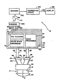
The invention is shown in block diagram form in Fig. 1.
Typically the invention is used in the surveillance of
premises such as warehouses, stores, bus or train stations
and the like. To this end, system 10 is provided with a lens
20 which has a substantially hemispherical field of view, for
example a fisheye lens. It is preferable to have an
azimuthal view of 180~, a zenithal view of 90~ and an
infinite depth of field. This produces the desired
substantially hemispherical field. The preferred lens is a
commercially available equidistant fisheye lens having a
focal length of 1.9 mm, and an f stop of 1.8. Lens 20 has a
primary axis Z and forms a circular image 14 on image plane
13.
35Due to the properties of lens 20, image 14 is distorted.
Specifically, the orientation of objects in image 14 is
altered relative to their real orientation. For example, an
object 11 in the field of view of lens 20 (See Fig. 8) will
CA 02220960 1997-11-13
WO 97/05741 PCT/US96/12332
appear on the periphery of image 14 in distorted form as
shown in Fig. 2.
Image 14 is preferably split into four separate
components by splitter 30. Image 14 could be split into any
S number of components, depending on the resolution required
and the available t~c-h~ology. When image 14 is split into
four components, each component respectively contains an
image 15, 16, 17 or 18 made up of one quadrant of circular
image 14. (See Fig. 2). Splitter 30 is made up of four
light conduits 25, 26, 27 and 28. Light conduits 25, 26, 27
and 28 respectively contain coherent fiber optic bundles 35,
36, 37 and 38 (See Fig. 4). Images 15, 16, 17 and 18 are
thus respectively carried in conduits 25, 26, 27 and 28 by
fiber optic bundles 35, 36, 37 and 38.
Splitter 30 is shown in greater detail in Figs. 3 and 4.
Splitter 30 is made up of a housing 32 to which are attached
conduits 25, 26, 27 and 28. Optical fiber bundles 35, 36, 37
and 38 housed in conduits 25, 26, 27 and 28 respectively,
branch off from a major bundle of fibers, terminating at
image plane 13 in a polished surface. See Fig. 4. Optical
fiber bundles 35, 36, 37 and 38, are each made up of a
plurality of optical fibers. Each optical fiber carries a
sample of image 14 formed by fisheye lens 20 and has a
diameter of approximately 10 ~m.
Images 15, 16, 17 and 18 respectively travel along each
of conduits 25, 26, 27 and 28 and impinge respectively upon
sensors 45, 46, 47 and 48. Sensors 45, 46, 47 and 48 are 768
x 480 CCD's with fiberoptic windows formed from a fiberoptic
faceplate which allows for direct coupling of the CCD's to
the optical fibers. Suitable fiberoptic faceplates are
available from Galileo Electro-optics Corporation of
Sturbridge, Massachusetts under the name "CP Series." Images
15, 16, 17 and 18 are respectively converted by the sensors
into representative electrical signals 55, 56, 57 and 58.
- 35 Signals 55, 56, 57 and 58 are fed into CCD control
processor 60 which is made up four identical off the shelf
video camera sensor image controllers 65, 66, 67 and 68, each
corresponding respectively to one of signals 55, 56, 57 or
CA 02220960 1997-11-13
WO97/05741 PCT~S96/12332
58. Each of the control processors contains a CCD clocking
circuit 72, a video processing circuit 74 and a color space
converter 76. Color space conversion circuit 76 produces
chrominance and luminance signals Cr, Cb and Y for each
signal 55, 56, 57 and 58.
Control processors 65, 66, 67 and 68 respectively
produce video ouL~uLs 85, 86, 87 and 88 in the form of
luminance and chro~;n~ce components suitable for compression
by encoder 100. Compression of the video signals 85, 86, 87
and 88 allows a very large number of image samples to be
transmitted over a ch~nnel having limited bandwidth. The
video outputs are therefore compressed if the lens is at a
location remote from correction circuit 140. Encoder 100
compresses the video signals 85, 86, 87 and 88 by compressing
them in accordance with a compression scheme, for example,
MPEG or H. 261. Alternatively, a sub-band coding scheme can
be used. Encoder 100 packetizes the video signals into a
serial data stream for transmission over high speed network
110 such as coaxial cable or optical fibers. The compressed
video signals are received by decoder 120 which performs a
transform on the compressed video signals which is the
inverse of the transform performed by encoder 100.
Decoder 120 produces a decoded video signal 130 which is
fed into correction circuit 140. The purpose of correction
circuit 140 is to correct the distortion introduced by
fisheye lens 20. This correction is performed in accordance
with the algorithm described below. Correction circuit 140
produces a corrected signal 150 which is displayed on display
160.
The following is a description of the system for
correcting the fisheye distortion of image 14. For the sake
of simplicity, it will be assumed that the entire fisheye
image 14 is formed on the surface of a single CCD 180 and
that splitter 30 is not used. CCD 180 has axes X and Y.
Lens 20 is mounted at a mounting point 17 vertically above
surveillance plane 19, preferably such that principal axis Z
is perpendicular to surveillance plane 19. Surveillance
plane 19 is the floor of a room 15. Mounting point 17 is on
CA 02220960 1997-11-13
wog7/os741 PCT~S96/12332
the ceiling of room 15. Axes X, Y and Z intersect at center
point I on the surface of CCD 180. The surface of CCD 180
forms image plane 13 which is parallel to surveillance plane
19 .
Mounting the camera and fisheye lens above the
surveillance field (i.e. on ceiling rather than on a wall)
has several advantages. Firstly, with the camera on the
ceiling, the field of view covers a full 360~. This allows
the simulation of a pan through 360~ rather than a pan range
limited by the presence of the wall. In the case of a
ceiling mounted lens, the hypothetical (simulated) pan axis
is the primary axis Z of the fisheye lens, rather than an
axis perpendicular to the primary axis in the case of a wall
mounted lens. The angle about the primary axis Z is
maintained from the object to the image. This facilitates
the calculation of radial coordinates because the pan axis is
already in radial form and no conversion is needed.
When any object is viewed on monitor 240, the vertical
center line of the image intersects the center point I of the
image plane. The primary axis Z of the lens passes through
this center point. There is therefore no need to rotate the
images to view them in their correct orientation. In the
correction algorithm set forth in U.S. Patent No. 5,185,667,
rotation of the image is separately calculated. Such a
separate operation is not needed with the present invention.
When the lens is placed on a wall, objects of interest
and objects which are furthest away tend to be at the center
of the fisheye image. The greatest resolution is needed to
view the details of those objects. When the fisheye lens is
placed vertically above the surveillance plane, objects in
the center are usually closest to the lens. Viewing of such
objects does not require high resolution and those objects
are the least distorted. Objects which are furthest away
from the lens appear at the peripheries of the fisheye image.
3S However, the image formed by a fisheye lens has a higher
density and therefore a lower CCD image resolution at the
center than at its peripheries. Consider a part of a
fisheye image having a radius of "R." The density of the
CA 02220960 1997-11-13
WO97/05741 PCT~S96112332
pixels in the CCD on which the image is formed is uniform.
Along a line passing through the center of the CCD, the image
is spread over 2R pixels. At the circumference of the image,
the image is spread over ~R (half the circumference) - ~/2
more pixels than for objects appearing at the center of the
image. Thus placing the lens vertically above the
surveillance plane provides far better resolution for distant
objects than if the lens is placed perpendicular to the
surveillance plane.
The following description refers to Fig. 5.
Fisheye lens 20 has a 180 degree field of view covering area
"A." With lens 20 is mounted on the ceiling of room lS, area
A includes the floor and walls of the room. Fisheye lens 20
forms a fisheye image Ad of area A on image plane 13. Any
point in area A represented by unique coordinates (x;y), is
displaced to point (xd;yd) in the fisheye image Ad in
accordance with the characteristics of fisheye lens 20.
Image plane 13 (the surface of CCD 180) is made up of a
matrix comprising a plurality of pixels 182. Each pixel has
unique fisheye coordinates. CCD thus produces an electronic
representation of area A. This representation is fed into
CCD control processor 250 (identical to control processor 60)
which produces chrominance and luminance values for each
pixel in CCD 180. Those chrominance and luminance values are
stored in dual ported image memory ("DPIM") 200. The present
invention allows the user to manipulate the fisheye image
electronically in order to implement the operations of
p~n~;~g, tilting and zooming. Thus a sub-area ~ of area A
can be examined in detail by the transformation of sub-area
~d of area Ad from a distorted fisheye image into a normal
image.
When the system is powered up a default corrected sub-
area ~cappears on monitor 240. The user selects sub-area
by means of area select unit 210 - a control station having
a keyboard and a pointing device. This is done by using
pointing device 214 to simulate the panning and a tilting of
a hypothetical conventional camera. The image on monitor 240
appears to have been formed by a conventional camera. In
CA 02220960 1997-11-13
WO97/05741 PCT~S96/12332
reality, it is formed by correction of part of fisheye image
14. The selection of sub-area ~ provides the normal (non-
fisheye) coordinates of an object in the center of sub-area
~. This operation simulates the pointing of the primary axis
(IC in Fig. 8) of hypothetical conventional camera at the
object. The hypothetical camera is mounted at mounting point
17 with its primary axis IC passing through center point I
and through the center of sub-area ~. Pointing this
hypothetical camera by means of input device 214 such that a
sub-area ~ appears on monitor 240 also causes area select
unit 210 to generate the pan and tilt angles which would be
associated with the hypothetical camera positioned at
hypothetical pan and tilt angles so that it points at an
object in sub-area ~.
When the user selects su~-area ~ the system
automatically converts ~d (the distorted fisheye image of area
a) into a corrected image ~c This allows the user to view
the sub-area ~ on monitor 240 as if it were formed by the
hypothetical (non-fisheye) camera which had been panned and
tilted to point at sub-area ~.
Each of the pixels in the fisheye image Ad is stored at
a unique address in DPIM 200 in the form of the intensity and
color data generated by CCD 180 via control processor 250.
DPIM 200 thus contains a digital electronic representation of
the distorted fisheye image Ad of area A. For any sub-area
of area A, DPIM 200 contains an electronic representation
of the corresponding distorted sub-area ~d.
Image plane 13 is the plane formed by the X and Y axes
as shown in Figs. 6, 7 and 8. Primary axis Z of lens 20 is
perpendicular to the X and Y axes. If a user wished to view
in detail the scene centered around point C (i.e sub-area ~-
the image shown in Fig. 2B) with a hypothetical non-fisheye
lensed camera, the user would instruct the camera to tilt by
an angle b relative to the primary axis Z. Doing so would
orient the hypothetical camera such that the hypothetical
primary axis (center line IC) passes through the center point
I of image plane 13 and through point C.
Had it been captured by the hypothetical conventional
CA 02220960 1997-11-13
W097/05741 PCT~S96/12332
camera, area a would appear on CCD 180 as an image 300
centered at line 320 and made up of a large number of
horizontal lines of pixels 310. (See Fig. 2A). Each pixel
on a particular horizontal line is displaced from center line
320 by a particular distance x. That distance corresponds to
an angle "a" relative to center line IC (See Fig. 8) or angle
a' about primary axis Z.
Each pixel in image 14 can be described by reference to
a set of rectangular or polar coordinates. Thus, referring
to Figs. 7 and 8, the pixel at point C on center line IC can
be located by reference to polar coordinates in the form of
tilt angle b (See Fig. ~) and angle a - the displacement of
the pixel from center (for point C, a is equal to zero since
C lies on the X axis). Similarly, moving along a horizontal
line in CCD 180 (i.e., moving parallel to the Y axis), a
pixel at point S can be described by reference to tilt angle
b' relative to principle axis Z and pan angle a' relative to
center line IC. The corresponding rectangular coordinates
are xd and Yd-
Referring again to Fig. 2A, it can be seen that due to
the nature of the fisheye lens, the fisheye image is
distorted. Objects located close to the principal axis of
fisheye lens 20 appear on CCD 180 substantially normally (See
area 182), whereas, objects further from the principal axis
are progressively more distorted (See area 184). The
information carried by a pixel located at point (x;y) in a
non-fisheye image will, in the fisheye image, be located at
(xd;yd), where (xd;yd) are displaced from (x;y) by an amount
dependent on the properties of fisheye lens 20.
It is a fundamental property of a fisheye lens that the
image of a point located at an angle of rotation b' relative
to the primary axis will be projected on the image plane a
radius r from the primary axis in accordance with the
formula:
r = f.b'
where r is the distance from center point I;
f is a lens constant in mm/radian indicative of the
distortion caused by the fisheye lens; and
CA 02220960 1997-11-13
W097/05741 PCT~S96/12332
b' is the angle of an incident ray from an object to the
primary axis (in rA~; ~n~) .
It is also a flln~ ntal property of a fisheye lens that
the angle from a point in the field of view to its projection
on the image plane is maintained.
These two properties are used to derive a new formula
which allows selected parts of the fisheye image to be viewed
as if they were formed by a conventional camera panned,
tilted or zoomed in on an area of interest in the field of
view. This formula relates the pan and tilt angles of a
hypothetical camera described above to the rectangular
coordinates of a corrected image. The following is a
description of how that formula is derived and applied to
achieve the objects of the invention.
From Fig. 6 it can be seen that a point C located at a
tilt angle b relative to the principal axis of the lens forms
an image on image plane IP at a radius r=rC from center point
I. As stated above, for a particular fisheye lens, the
relationship between tilt angle b and the radius at which the
image of point C forms is:
r=f.b........................................ (l)
In Fig. 8, point C lies in the plane formed by the Y and
Z axes and at a tilt angle of b relative to the primary axis
Z. The line IC from the center I of the image plane to point
C is taken as the primary axis of a hypothetical camera lens
pointed at point C. Line CS extends from point C to a point
S. CS is parallel to the X axis. CS thus represents a
horizontal line of pixels in CCD 180. Consider a pixel at
S, at a particular radius r from I, the center of the CCD,
and at a pan angle "a"' about the primary axis of the
hypothetical camera lens and at a tilt angle b' relative to
the primary axis of the fisheye lens. The rectangular
coordinates of that pixel are:
X=f.b'.cos(a')............................... ..(2)
Y=f.b'.sin(a')............................... ..(3)
Equations (2) and (3) convert the polar coordinates of
any particular pixel of the fisheye image formed on CCD to
rectangular coordinates. The pixel at point S can therefore
11
CA 02220960 1997-11-13
WO 97/05741 PCT/US96/12332
be located by reference to tilt angle b' (an angle measured
off the principal axis Z) and pan angle a' (the angle of
rotation around the principal axis Z).
When the system powers up a default area a is displayed,
corresponding to the initial area at which the hypothetical
camera is pointing. For convenience, this area lies along
the primary axis Z (so the tilt angle b is zero). The pan
angle is also zero (i.e., line IC lies along the X axis).
The hypothetical camera (with the primary axis of its lens
lying along line IC) is then tilted by an angle of "b"
relative to the primary axis Z of the fisheye lens so that it
points at an object centered at point C. In order to make
the operation of the correction system transparent to the
user, the panning and tilting of the hypothetical camera is
measured relative to the initial position of the hypothetical
camera. Thus, the position of a pixel representing a point
at S will be expressed in terms of tilt angle "b" and the
angle of point S from center line IC - angle "a" the amount
of pan from center line IC to point S.
The following is a description of the manner in which
the position of a pixel representing point S in the fisheye
image can be described by reference to angle a - its
displacement from the center line IC and angle b - the tilt
angle of a hypothetical normal camera panned and tilted so
that it's principal axis is aligned with point C.
Referring to Fig. 8, it is seen that
tan(a') = SC/PC
SC=IS.sin(a)
PC=IC.sin(b)
IC=IS.cos(a)
therefore tan(a') = IS.sin(a)/IS.cos(a).sin(b)
= tan(a)/sin(b)
a'=tan~1(tan(a)/sin(b))....................... (4)
cos(b') = IP/IS
IP=IC.cos(b)
IC=IS.cos(a)
therefore cos(b') = IS.cos(a).cos(b)/IS
= cos(a).cos(b)
12
CA 02220960 1997-11-13
WO97/05741 PCT~S96/12332
b' = cos~1(cos(a).cos(b))..................... ..(5)
From equations (2) and (3), for a given fisheye
lens, Xd=fb'cos(a') and Yd=fb'sin(a'). Substituting the
values of a' and b' from equations (4) and (5) into equations
(2) and (3):
Xd= f.cos~1(cos(a).cos(b)).cos(tan~1(tan(a)/sin(b)))...(6)
Yd= f.cos~1(cos(a).cos(b)).sin(tan~1(tan(a)/sin(b)))...(7)
These formulas allow the coordinates of the pixels
centered around center line IC to be calculated simply from
knowledge of angular coordinates in the form of the tilt
angle "b" of a hypothetical camera (a measure of the distance
of the point from the center of the fisheye image) and the
angle "a" of a pixel relative to center line IC. This
formula provides a very simple means for effectuating
r~n"ing, tilting and zooming from the fisheye image.
To effect panning of the hypothetical camera, pan angle
p is added to angle a' to form new angle a". Thus, a"= p +
a'.
Substituting this into e~uation (4) gives:
a"= p + tan~1(tan(a)/sin(b))...................... (8)
Substituting equation (a) into equations (6) and (7):
Xd=f.cos~1(cos(a).cos(b)).cos(p + tan1(tan(a)/sin(b))
(9)
Yd=f.cos~1(cos(a).cos(b)).sin(p + tan1(tan(a)/sin(b))
(10)
As pointing device 214 is moved to simulate panning
and/or tilting of the hypothetical camera, the rectangular
coordinates (X;Y) of each pixel in each line of pixels in
sub-area ~ are generated by area select unit 210 and stored
in look-up table ("LUT") 222. The system also automatically
calculates the coordinates (Xd;Yd) of the fisheye image from
the using equations (9) and (10). For each set of normal
coordinates (X;Y) in sub-area ~, the calculated coordinates
(Xd;Yd) are stored in LUT 222 as addresses in DPIM 200.
All of the coordinates for the fisheye image could be
pre-calculated or only the coordinates for a particular area
need be calculated as the area is selected. In either case,
the coordinates are stored in LUT 222 and the corresponding
13
CA 02220960 lss7-ll-l3
WO97/05741 PCT~S96/12332
pixels are stored in DPIM 200. This allows the pixels
corresponding to those calculated coordinates to be fetched
from CCD 180. The fetched pixels are then displayed on
monitor 240 at locations (X;Y) just as if the image had been
~ormed by the panning and tilting of a normal camera to
coordinates (X;Y).
Zooming can be accommodated by varying the amount that
angle a is incremented between pixels and the amount b is
incremented between rows when calculating the contents of LUT
222. For example, if there are 400 pixels on a horizontal
display line and a is incremented from -20O for the left side
of the display in steps of .1~, a 40~ horizontal field of
view will result. Likewise, to display a 30~ vertical field
of view that would correctly maintain the 4:3 aspect ratio of
a standard display, the 483 display lines would be obtained
by incrementing b by .062~ between each horizontal display
line.
The contents of LUT 222 and DPIM 200 are represented in
the following table:
TABLE I
ADDRESS FEA ~R~TOR LUT DUAL PORT MEMORY
SE~N~: FOR CONTENTS CONTENTS
BOTH DATA
STRUCTURES
25Starting Address of 1st 1st pixel 1st
Address pixel of 1st row row
S.arting Add. of 2nd pixel 2nd pixel 1st
Address + 1 of 1st row row
Starting Add. of 1st pixel 1st pixel 2nd
Address + H of 2nd row row
Starting Add. of 2nd pixel 2nd pixel 2nd
35 Address + H + 1of 2nd row row
SUBSTITUTE SHEET (RULE 26)
CA 02220960 1997-11-13
WO97/05741 PCT~S96/12332
Starting Add. of 1st pixel 1st pixel 3rd
Address + 2H of 3rd row row
Starting Add. of 2nd pixel 2nd pixel 3rd
5Address + 2H +of 3rd row row
.
.
.10
H = Number of pixels per line in display processor.
By retaining multiple images in DPIM 200, a historical
log of images over time can also be stored. The oldest image
is continually overwritten with the current image as the
:L5 memory capacity is exceeded, thus maintaining a revolving log
of images generated over a predetermined time period. Thus,
by appropriate selection of an address in DPIM 200 by fisheye
address generator, images captured in the preceding
predetermined time interval can be displayed when an alarm
:~0 event occurs (e.g. an intruder attempting to enter the
monitored premises and triggering a sensor).
Using a 360 degree image, this system implements the
operations of panning and tilting without any moving parts.
This increases the reliability of the camera while limiting
the cost of acquiring and maintaining it. The invention thus
enables the monitoring of a large area by means of a single
camera covering a wide field of view.
SUBSmUTE SHEET (RULE 26)