Note: Descriptions are shown in the official language in which they were submitted.
CA 02221062 1997-11-14
INJECTION/ISOLATION TOOL
Field of the Invention
This invention is directed to a downhole tool and method for use thereof and,
in
particular, a tool and method for downhole isolation and injection.
Background of the Invention
In the production of oil and/or gas, in addition to the production of the
desired fluid,
sometimes a heavier fluid is produced. These heavier fluids must be separated
from
the oil and gas and disposed of.
Preferably, the undesired heavier fluids are separated from the desired fluids
downhole
and are injected into a disposal formation without being brought to ground
surface.
Where the disposal formation is located above the production formation, an
uphole
injection tool is required to be used to effect such downhole separation.
An uphole injection tool is disclosed in U.S. Patent 5,579,838 of Michael. The
tool
which is disclosed handles the lighter fluids and heavier fluids separately
after they
have been separated by residence time downhole. The tool includes an assembly
having a first conduit for movement of heavy fluids and a second conduit for
movement
of lighter fluids. A pump is provided for moving the heavier fluids. The first
conduit
opens via a plurality of ports into a disposal formation for injection of the
heavier fluids
thereto.
The tool of Michael has limited use however as the ports to the disposal
formation are
CA 02221062 1997-11-14
-2-
permanently open. These ports prevent isolation of the disposal formation from
the
production formation and limit selective access to the production formation by
fluids
injected from the surface.
An uphole injection tool is required that can also be used to selectively
isolate the
disposal zone from the other zones.
Summar)r of the Invention
A downhole tool has been invented which can be used for injection of waste
fluids
which have been separated from desired production fluids into a disposal
formation.
When desired, the conduit for the waste fluids to the disposal formation can
be closed
off, thereby isolating the disposal formation from the production zone and
providing
access selectively to the production zone.
In accordance with a broad aspect of the present invention, there is provided
a
downhole tool comprising: an inner tube having a bore and being connectable at
each
end to a tubing string; an outer tube having a outer surface and being
disposed about
and spaced from the inner tube; an annulus between the inner tube and the
outer tube;
upper and lower openings from the outer surface of the outer tube to the
annulus; an
upper well sealing means disposed on the outer tube below the upper opening
for
providing an annular seal between the casing and the outer tube; a lower well
sealing
means disposed on the outer tube above the lower opening for providing an
annular
seal thereabout; a transverse port positioned on the tool between the upper
well sealing
means and the lower well sealing means, the transverse port extending to
provide
access between the bore of the inner tube and the outer surface of the outer
tube
without opening into the annulus and a means for opening and closing the
transverse
port.
In accordance with another broad aspect of the present invention, there is
provided a
CA 02221062 1997-11-14
-3-
downhole tool comprising: an inner tube having a bore with a known cross
sectional
area and being connectable at each end to a tubing string; an outer tube
having an
outer surface and being disposed about and spaced from the inner tube; an
annulus
between the inner tube and the outer tube; upper and lower openings from the
outer
surface of the outer tube to the annulus; an upper well sealing means disposed
on the
outer tube below the upper opening for providing an annular seal between the
casing
and the outer tube; a lower well sealing means disposed on the outer tube
above the
lower opening for providing an annular seal thereabout; a transverse port
positioned on
the tool between the upper well sealing means and the lower well sealing
means, the
transverse port extending to provide access between the bore of the inner tube
and the
outer surface of the outer tube without opening into the annulus, the
transverse port
having a minimum cross sectional area equal to or greater than the cross
sectional area
of the bore of the inner tube.
In accordance with yet another broad aspect of the present invention, there is
provided
a downhole tool for use within a casing of a well, the downhole tool
comprising: an
inner tube having a bore and an outer surface and being connectable at each
end into
a tubing string, the inner tube defining a fluid conduit cross sectional area
between the
outer surface of the inner tube and the casing in which the downhole tool is
used; an
outer tube having an outer surface and being disposed about and spaced from
the inner
tube; an annulus between the inner tube and the outer tube, the annulus having
a
minimum cross sectional area which is greater than or equal to 17% of the
fluid conduit
cross sectional area; upper and lower openings from the outer surface of the
outer tube
to the annulus; an upper well sealing means disposed on the outer tube below
the
upper opening for providing an annular seal between the casing and the outer
tube; a
lower well sealing means disposed on the outer tube above the lower opening
for
providing an annular seal thereabout; a transverse port positioned on the tool
between
the upper well sealing means and the lower well sealing means, the transverse
port
extending to provide access between the bore of the inner tube and the outer
surface
of the outer tube without opening into the annulus.
CA 02221062 1997-11-14
-4-
In accordance with yet another broad aspect of the present invention there is
provided
a method for passing waste fluids through a well borehole from a production
layer to a
disposal layer disposed above the production layer, the well borehole having a
wall
extending from surface, comprising;
providing a downhole tool including an inner tube having a bore and being
connectable at each end to a tubing string; an outer tube having a outer
surface and
being disposed about and spaced from the inner tube; an annulus between the
inner
tube and the outer tube; upper and lower openings from the outer surface of
the outer
tube to the annulus; an upper well sealing means disposed on the outer tube
below the
upper opening for providing an annular seal between the casing and the outer
tube; a
lower well sealing means disposed on the outer tube above the lower opening
for
providing an annular seal thereabout; a transverse port positioned on the tool
between
the upper well sealing means and the lower well sealing means, the transverse
port
extending to provide access between the bore of the inner tube and the outer
surface
of the outer tube without opening into the annulus and a means for opening and
closing
the transverse port;
connecting the inner tube to a lower tubing section including a pump;
positioning the tool, upper tubing section and lower tubing section in the
borehole
such that the pump is in pumping communication with waste fluids passing from
the
production zone;
setting the upper sealing means and the lower sealing means to seal between
the outer tube and the borehole wall, the upper sealing means and the lower
sealing
means being disposed around an access point to a disposal zone;
activating the pump to move waste fluids through the inner tube bore and out
the
transverse port into the disposal zone when the port is open.
In accordance with yet another broad aspect of the present invention there is
provided
a method for passing waste fluids through a well borehole from a production
layer to a
disposal layer disposed above the production layer, the well borehole having a
wall
CA 02221062 1997-11-14
-5-
extending from surface, comprising;
providing a downhole tool including an inner tube having a bore with a known
cross sectional area and being connectable at each end to a tubing string; an
outer tube
having an outer surface and being disposed about and spaced from the inner
tube; an
annulus between the inner tube and the outer tube; upper and lower openings
from the
outer surface of the outer tube to the annulus; an upper well sealing means
disposed
on the outer tube below the upper opening for providing an annular seal
between the
casing and the outer tube; a lower well sealing means disposed on the outer
tube
above the lower opening for providing an annular seal thereabout; a transverse
port
positioned on the tool between the upper well sealing means and the lower well
sealing
means, the transverse port extending to provide access between the bore of the
inner
tube and the outer surface of the outer tube without opening into the annulus,
the
transverse port having a minimum cross sectional area equal to or greater than
the
cross sectional area of the bore of the inner tube;
connecting the inner tube to a lower tubing section including a pump;
positioning the tool, upper tubing section and lower tubing section in the
borehole
such that the pump is in pumping communication with waste fluids passing from
the
production zone;
setting the upper sealing means and the lower sealing means to seal between
the outer tube and the borehole wall, the upper sealing means and the lower
sealing
means being disposed around an access point to a disposal zone; and
activating the pump to move waste fluids through the inner tube bore and out
the
transverse port into the disposal zone.
In accordance with yet another broad aspect of the present invention there is
provided
a method for passing waste fluids through a well borehole from a production
layer to a
disposal layer disposed above the production layer, the well borehole having a
wall
extending from surface, comprising;
providing a downhole tool including an inner tube having a bore and an outer
surface and being connectable at each end into a tubing string, the inner tube
defining
CA 02221062 1997-11-14
-6-
a fluid conduit cross sectional area between the outer surface of the inner
tube and the
wall of the borehole in which the downhole tool is used; an outer tube having
an outer
surface and being disposed about and spaced from the inner tube; an annulus
between
the inner tube and the outer tube, the annulus having a minimum cross
sectional area
which is greater than or equal to 17% of the fluid conduit cross sectional
area; upper
and lower openings from the outer surface of the outer tube to the annulus; an
upper
well sealing means disposed on the outer tube below the upper opening for
providing
an annular seal between the borehole wall and the outer tube; a lower well
sealing
means disposed on the outer tube above the lower opening for providing an
annular
seal between the outer tube and the borehole wall; a transverse port
positioned on the
tool between the upper well sealing means and the lower well sealing means,
the
transverse port extending to provide access between the bore of the inner tube
and the
outer surface of the outer tube without opening into the annulus;
connecting the inner tube to a lower tubing section including a pump;
positioning the tool, upper tubing section and lower tubing section in the
borehole
such that the pump is in pumping communication with waste fluids passing from
the
production zone;
setting the upper sealing means and the lower sealing means to seal between
the outer tube and the borehole wall, the upper sealing means and the lower
sealing
means being disposed around an access area to a disposal zone; and
activating the pump to move waste fluids through the inner tube bore and out
the
transverse port into the disposal zone.
Brief Description of the Drawinas
A further, detailed, description of the invention, briefly described above,
will follow by
reference to the following drawings of specific embodiments of the invention.
These
drawings depict only typical embodiments of the invention and are therefore
not to be
considered limiting of its scope. In the drawings:
CA 02221062 1997-11-14
-7-
Figure 1 shows a schematic representation of a vertical section along a cased
borehole, the borehole having a injection/isolation tool disposed therein;
Figures 2A, 2B, 2C and 2D show front elevations of an injection/isolation tool
according to the present invention; and,
Figures 3A and 3B are cross sectional views along lines A and B, respectively,
of Figure 2C.
Detailed Description of the Present Invention
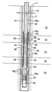
Referring to Figure 1, a sectional schematic view along a well is shown. The
well
borehole, indicated at 10, passes from surface 11 through a formation
including an
upper layer 12, an impermeable rock layer 13, a disposal layer 14 which is
permeable
rock, a second impermeable layer 15 and a production layer 16. Borehole 10 is
lined
with a casing 17 and is completed to prevent interzonal migration in the
casing annulus.
Upper perforations 18a are formed in casing 17 to provide access from the
casing tube
to the disposal layer 14 and lower perforations 18b are formed in casing 17 to
provide
access to production layer 16. The production layer 16 produces both a desired
lighter
fluid, such as oil and/or gas, and a heavier waste fluid, such as water. Both
the fluids
pass from the production layer through perforations 18b into casing 17. After
a suitable
residence time in the casing, for example one minute, the lighter fluids, such
as gas, will
be separated from the heavier fluids. Lighter fluids, such as gas, will pass
by the forces
of density and pressure up the borehole, as indicated by arrows L. Lighter
fluids such
as oil may require active separation from the waste fluids and may further
require active
pumping up the borehole after they are separated from the heavier fluids. The
heavier
fluids will pass by gravity further down the borehole, as indicated by arrows
H.
The injection/isolation tool according to the present invention is shown
schematically
in Figure 1 and is generally indicated as 20. Tool 20 provides a conduit for
lighter fluids
CA 02221062 1997-11-14
_g_
moving towards surface 11 and injects heavier fluids into disposal layer 14.
The tool
can alternately be used to isolate a portion of the casing or well bore from
the remainder
of the casing or well bore while remaining a conduit to fluids moving towards
surface
11. For use, tool 20 is preferably connected at its upper end into an upper
tubing string
22 and, at its lower end, to a lower tubing string 23 preferably to which is
attached or
includes a pump 24. Pump 24 can be any suitable pump for downhole operation
such
as , for example, a rod pump, as shown, a progressing cavity pump or an
electric
submersible pump. The pump includes an inlet port 25 which provides access to
the
bore 23a of tubing string 23.
Tool 20 includes an inner tube 30 connectable directly to tubing strings 22
and 23 such
that the inner bore 30x of inner tube 30 opens into the inner bores 22a and
23a of
tubing strings 22 and 23 and a unitary conduit is formed through the tubing
strings 22,
23 and tube 30. Tubing strings 22 and 23 and tube 30 are connected in any
suitable
way such as, for example, by standard tubing collars, threaded and/or non-
threaded
connections.
An outer tube 34 is mounted substantially concentrically about inner tube 30.
Outer
tube 34 is mounted in spaced relation from inner tube 30 such that an annulus
36 is
formed there between. Inner tube 30 and outer tube 34 are mounted together and
annulus 36 is formed by any desired process such as by milling along the
length of a
wall of a tube to form an inner tube and an outer tube which are connected and
have
an annulus there between. Alternately, and as shown in the depicted
embodiment,
spacers 38 are secured between inner tube 30, and outer tube 34, for example
by
welding or fasteners, to maintain the spacing there between. Spacers 38 are
disposed
between the tubes such that annulus 36 is not at any point completely blocked
off and
an open path is provided through the annulus between the lower and upper ends
of
tubes 30, 34.
The tool also includes at least one transverse port 40 which extends between
and
CA 02221062 1997-11-14
_g_
connects the inner bore 30x of inner tube 30 to the outside of the tool
without opening
into the annulus 36. Each port 40 is formed in any suitable way, for example
by placing
a tube in sealing arrangement between openings formed in inner tube 30 and
outer
tube 34. Where a spacer 38 is used to form annulus 36, port 40 can be formed
conveniently by drilling an opening through the spacer, as shown. In so doing,
it is
necessary that a seal be provided at the interface between the spacer and the
tubes
where the port passes to prevent passage of fluid from the port through the
interface.
A means is provided for selectively opening and closing port 40. In the
illustrated
embodiment, a sliding sleeve valve 46 is mounted on tool to provide for
closure of port.
Sleeve 46 is disposed in the bore 30x of inner tube 30 and is moveable in the
bore
between a position in which port 40 is not blocked by sleeve 46 and a position
in which
sleeve 46 is disposed over and blocks port 40. Sealing means 48, such as O-
rings or
lip seals, are provided to effect a seal between sleeve 46 and tube 30.
Well sealing means 50, 52, such as packers, are provided on the exterior of
tube 34 for
effecting a seal between tube 34 and casing 17. Sealing means 50 is provided
adjacent the upper end of tube 34, while sealing means 52 is provided adjacent
the
lower end of tube 34. Sealing means 50, 52 can be a packer or any other
sealing
means which can be placed around a tube to block passage of fluid about the
tool and
through the well bore. Preferably, the sealing means are retractible so that
the well
bore seal can be removed and the tool is removable from the well. For example,
the
sealing means can be an inflatable/deflatable or a mechanical packer.
Referring to Figures 2A to 2D, 3A and 3B, a preferred embodiment of the tool
is shown
to facilitate manufacturing of the tool and to facilitate selection of the
length of the tool,
the tool 20 is preferably made by assembly of about four main parts. In
particular, the
tool preferably includes an upper section 20a (Figure 2A), an upper middle
section 20b
(Figure 2B), a lower middle section 20c (Figure 2C) and a lower section 20d
(Figure
2D). To assemble the tool, the sections are fit together in series. The
sections of the
,CA 02221062 2005-04-05
-10-
tool are maintained in engagement preferably by' threading or, for example, by
welding.
As would be commonly understood by a man skilled in the art, sections 20a to
20d can
be formed in any suitable way, for example, by a plurality of smaller parts
shaped by,
for example, milling to be fit together. To simplify the description, each of
the smaller
parts will not be described in detail. The tool is preferably formed from a
material which
is substantially inert to well fluids such as, for e;cample, a steel alloy
which is resistant
to hydrogen sulphide gas.
Inner tube 30 of the tool is formed by: fitting inner tube end 30b of upper
middle section
into inner tube end 30a' of upper section; fitting upper end 30c of the inner
tube from
lower middle section 20c into end 30b'; and fitting end 30d into end 30c'. The
sections
of tube 30 are fit together by any suitable means such as by tapered fittings
or seal
rings which contain sealing means or which provide metal on metal seals or,
where
possible, threaded fittings.
Outer tube 34 is formed by fitting ends 34a' and 34b, 34b' and 34c and 34c'
and 34d
together and fitting connector rings, for example 59, thereover, as required.
O-rings 60,
or other suitable sealing means, such as metal on metal seals, are provided at
the
connections to effect a seal against the passage of fluids through the joints.
Ends 30a and 30d'of tube 30 are formed for threaded connection into a tubing
string.
Outer tube 34 is mounted about and spaced from inner tube 30 by spacers 38.
Spacers 38 are formed integral with inner tube 30 and outer tube 34 is welded,
indicated at 39a and 39b, thereon. Slots can b~~ provided or formed in outer
tube 34 to
facilitate such welding. Weld 39b is preferable made such that it effects a
seal at the
interface between spacer 38 and outer tube 34. Such a weld can conveniently be
made
by welding through a small port formed in the outer tube. After welding the
parts
together, preferably, three ports 40 are formed, as by drilling, through the
spacers to
provide access between bore 30x of inner tube 30 and the outside of the tool.
CA 02221062 1997-11-14
-11-
Preferably, to provide a secondary seal at the interface of the spacer and the
outer tube
where port 40 passes there through, preferably, port 40 is threaded and a
liner 41 is
secured therein.
T.~..F.....:1:+...+.., .. ...i+L.... t-.W :~ _ n__e_~ u_ _n~___
~ v ia~.mua~G use u1 LI IC LVVI Ifl fllovlflg'. a nma m a aisposai layer, the
pores are preferably
formed such that their combined smallest cross sectional area is substantially
equal to
or greater than the smallest cross sectional area of the bore of the tube
conveying fluid
from the pump to the ports, termed herein the fluid conduit cross sectional
area. The
tube referred to can be either inner tube 30 or the tubing string 23 connected
at the
lower end thereof. For example, in a tool according to the preferred
embodiment for
use with pump tubing of 2.375 in. OD and fluid conduit cross sectional area of
2.835
in.2, three transverse ports 40 are provided each having a minimum cross
sectional area
of .935 in.2, for a total combined sectional area for the three ports of about
2.835 in.2.
Preferably, the cross sectional area of bore 30x is also 2.835 in.2 to further
facilitate
passage of fluids.
Annulus 36 is formed between the tubes 30, 34. Annulus 36 opens to the
exterior of
the tool at openings 66, 68. In one embodiment, the cross sectional area of
the annulus
is maximized in the tool to facilitate passage of gas there through and to
provide the
lowest pressure drop across the tool. Preferably, the minimum cross sectional
area of
annulus 36 is selected to be equal to or greater than 17% of the minimum cross
sectional area of the fluid conduit through the borehole. The fluid conduit in
a borehole
is generally the annulus 19 (Figure 1 ) between the tubing string, for example
22, or the
inner tube 30 and the casing 17. In the illustrated embodiment, the minimum
cross
sectional area of annulus 36 is depicted in Figure 3A. This is the area where
the walls
of transverse ports 40 are located. In a well having a 5.5" ID casing and a
2.375" OD
tubing string, the annulus between tubing string and the casing wall is 14.815
in.2 . A
preferred tool for such a well has a minimum cross section annulus (36) area
of 2.6 in.2
which is 17.5% of the area of the annulus between the casing and the tubing
string.
The maximum cross sectional area of the annulus between the outer tube and the
inner
,CA 02221062 2005-04-05
-12-
tube that can be achieved in a tool according to the present invention is
dependent on
a number of factors including the diameter of the tool which can reasonably
expected
to fit into the well, the thickness of the material which is used for
construction of the tool
and the diameter of the inner bore which is required.
Sliding sleeve 46 is disposed within tube 30 and is slidably moveable therein
between
a first position in which the sleeve does not blo~:,k ports 40 and the ports
are open, as
shown in Figures 2C and 3C, and a second posii.ion in which sleeve 46 is
disposed over
and blocks ports 40. In accordance with the pre:~ent invention, the ports can
be opened
by sliding the sleeve longitudinally or rotationally. Preferably, the opposing
surfaces of
the sleeve and tube are plated with a suitable m~~terial such as nickel to
resist corrosion.
In the illustrated embodiment, the sleeve is moved by sliding it
longitudinally within tube
30. Circumferential sealing elements 48, such as O-rings, are housed in slots
formed
at least adjacent the ends of the sleeve thereby substantially preventing
leakage of fluid
between the sleeve and the tube. The seals can also act as cylinder wipers to
reduce
the likelihood of foreign material entering between the sleeve and the tube.
A mating assembly 90 is provided to guide the sleeve 46 between the first and
second
positions. The assembly includes at least one, .end preferably three, detents
extending
from the internal surface 96 of tube 30 into corresponding guide slots 100 in
an external
surface 92 of sleeve 46. Each detent preferak~ly includes ball 105 biased
towards its
slot 100 and indentations 102, 104 by an elastic; member, such as for example,
spring
106, as shown, or rubber blocks. A first indent~~tion 102 and a second
indentation 104
in the slots 100 are snap engaged by ball 105, as will be described below,
when the
sleeve 46 reaches the first and second positions, respectively. Thus, a
positive
indication is provided when the sleeve is retractE~d fully from over the ports
40 and when
the sleeve is positioned over the ports. While tree mating assembly has been
described
and shown according to one embodiment, the assembly 90 can take other forms.
For
example, the assembly can comprise at le:~st one and preferably a plurality of
protrusions such as pins or balls, extending from an external surface 92 of
the sleeve
,CA 02221062 2005-04-05
-13-
46 or an internal surface 96 of the tube 30. The groove can be formed on
either the
internal surface 96 or the external surface 92 to matingiy receive the
protrusions.
Preferably, the detent assemblies including balls 105 and springs 106 are
accessible
from the exterior of the tool. For example, in them depicted embodiment, each
ball and
spring assembly is disposed in a port 107 in th~~ tool which extends though
the outer
tube 34, through a solid spacer 108 disposed in 'the annulus and through the
inner tube
30. Ports 107 are preferably formed in a mannE:r similar to ports 40. In the
illustrated
embodiment, solid spacer 108 is formed inteclral with inner tube 30. Each
detent
includes a generally cylindrical plug 109 which is threadably engaged in port
107. Seals
110 are provided to seal between plug 109 and port 107. The plug has a first
end 111
which is open to the exterior of the tool. The ela;~tic members act against
the plugs 109
to bias the spherical members 105 towards slats 100. The removability of plug
109,
allows the tension in the elastic member to be ~sdjusted, or the spring to be
replaced,
to thereby adjust the threshold actuation force nE:cessary to move the sleeve
46 without
disassembly of the tool.
Sleeve 46 is limited in its range of movement within tube 30 by shoulders 112,
113.
The sleeve is moved between the first and the second position by a downhole
tool (not
shown), as is known. For example, the downhole tool include a housing having
spring
loaded dogs mounted therein adapted to fit within a groove 114 formed in the
inner
surface of the sleeve 46. The tool engages the sleeve when the dogs spring
from the
housing into the groove. The sleeve is then moveable between the first and
second
positions, as the tool is moved, e.g. as the tool is fed into or out of the
well by way of
tubing extending from the tool to the surface.
Tool 20 further includes a sealing member 50 at its upper end and another
sealing
member 52 at its lower end. The sealing members are each, in the preferred
embodiment, inflatable packers. The packers include an inflatable jacket 115
which can
be for example a rubber containing material such as Neoprene that is resistant
to
CA 02221062 1997-11-14
-14-
hydrocarbon fluids and other well bore fluids. Preferably the packers are
mounted on
sections 118 along the outer tube 34 which are of reduced outer diameter when
compared to the remainder of the outer tube. This permits the jackets to be
mounted
in recesses in the outer tube to, thereby protect the jackets from damage
during
insertion of the tool into the well. To facilitate manufacture, these sections
118 are
produced separately from the remainder of the outer tube and are mounted
thereto.
The jackets are inflated by a flowing fluid from within the tube bore 30x. The
flowing
fluid enters through opening 120 and flows through a port 122, shown in
phantom, to
a line 124, also shown partially in phantom, which is in communication with
jacket 115.
Valves (not shown) control the flow of fluid into and out of the jacket. A
packer system
including an inflatable jacket and a valve which is useful in the present
invention is
known as an Annulus Casing Packer T"" available from McAllister Petroleum
Services
Ltd.
Preferably, the length of tool 20 is selected, with consideration as to the
borehole
characteristics, such that it is longer than the length of the section
perforated with
perforations 18a through casing 17. In particular, the length of the tool is
selected such
that when the tool is placed in the cased borehole, port 40 is positioned
adjacent
disposal layer 14, packer 52 is disposed below perforations 18a and packer 50
is
positioned above perforations 18a to prevent the injected fluid from moving up
the
annulus about the tool. Further, the pump 24 is positioned below the tool a
suitable
length such that it is in pumping communication with the waste fluids being
produced
in the production layer. This is generally a position below perforations 18b.
After placement of the tool, packers 50, 52 are set to seal between the tool
and the
casing wall or borehole wall. Where the packers are of the type requiring
inflation,
sleeve 46 must be in the closed position across ports 40 during packer
inflation. To
facilitate installation of the tool, sleeve 46 is positioned over ports 40
during placement
of the tool.
CA 02221062 1997-11-14
-15-
If it is desired to use the tool for isolation of a zone, the sleeve 46 is
moved or remains,
depending on its position during tool placement and/or inflation of the
packers, so that
it blocks the ports 40. If it is desired to use the tool for uphole injection,
the sleeve is
moved or remains retracted from over ports 40 so that the ports are open for
passage
of fluids.
In a producing well, any produced waste fluids are separated from the produced
lighter
fluids by residence time. As noted previously, the lighter fluids will pass up
the
borehole. When the lighter fluids reach tool 20, packer 52 prevents the fluids
from
moving around the tool and the fluids enter annulus 36 through opening 68.
Because
annulus 36 is open along the length of the tool, the lighter fluids pass
through the
annulus and out through opening 66. The fluids will then continue up the
borehole
towards the surface.
The waste fluids flow by gravity downwardly in the well bore. When it is
desired to inject
the waste fluids in a disposal formation 14, the pump is actuated to move the
waste
fluid. By action of the pump, the waste fluids are drawn through inlet port 25
into bore
23a of tubing string 23 and thereafter into bore 30x of inner tube 30. When
the fluids
reach ports 40, the fluids flow out through the ports and into the annulus
between the
tool and casing 17. Packer 52 prevents the fluids from passing down the well
bore and
packer 50 prevents the fluids from filling up the annulus. Thus, the fluids
pass through
perforations 18a in the casing and into the disposal layer.
'~~l~ien ;t~s desirei.I t'~-intrfrdW a fiuid5-Gr tvvij tV t he p1 VdIII~IIVII
layel 10, sleeve 4D C:dfl
be moved to close ports 40 and thereby isolate the disposal layer from the
production
layer. When it is desired to resume uphole injection into the disposal layer,
it is
necessary to move the sleeve to open the ports to provide access to the
disposal zone.
To remove the tool from the well, the packers can be reversed, for example by
deflating
them, and the tool can be pulled from the well. As would be understood, where
uphole
CA 02221062 1997-11-14
-16-
injection was conducted, the perforations may have to be patched to prevent
leakage
of the waste fluid back into the casing.
It will be apparent that many other changes may be made to the illustrative
embodiments, while falling within the scope of the invention and it is
intended that all
such changes be covered by the claims appended hereto.