Note: Descriptions are shown in the official language in which they were submitted.
CA 0222ll40 l997-l2-02
W O 96/40030 PCT~US9G/~9~15
ABSORBENT ARTICLE HAVING ELASTICIZED BUMPERS AND METHOD OF MANUFACTURE
Backqround of the Invention
The present invention relates to articles for containing and absorbing
body fluids. More particularly, the invention pertains to an absorbent
article including elasticized bumpers that conform to the shape of the
wearer and reduce the potential for side leakage. The invention also
pertains to a method of making such an absorbent article.
Disposable absorbent artlcles such as diapers, training pants, feminine
care products and adult incontinence products have been constructed in an
effort to contain and absorb urine and other body exudates. Most of these
absorbent articles include several common components. Specifically,
disposable absorbent articles routinely include a liquid permeable bodyside
liner, a liquid impermeable backing sheet, and an absorbent material
disposed between the bodyside liner and the backing sheet. These products
also include some form of attachment system, although the specific type may
vary among fastening tapes, belts, garment adhesive, elastic straps,
mechanical fasteners, integral side panels, or the like.
One common concern in designing the foregoing type of disposable
absorbent article is leakage, and in particular leakage of liquid from the
side edges of the article. A wide variety of special components have been
developed and added to absorbent articles in order to reduce the instances
of side leakage. For instance, many absorbent articles include elastic
structures positioned along the sides of the absorbent material and stretch
bonded to the bodyside liner and backing sheet. The elastic structures are
intended to gather the side portions of the article and form seals, gaskets
or barriers to impede the flow of liquid past the side edges of the article.
In addition to leg elastic structures, absorbent articles have also included
CA 02221140 1997-12-02
W O 96/40030 PCTAUS96/090~5
elasticized containment flaps which stand up from the surface of the
bodyside liner, again in an attempt to control the movement of liquid as
well as other body wastes toward the side edges of the article.
Despite the demonstrable improvement in containing body wastes, and in
particular urine, afforded by such elasticized structures, absorbent
articles are still subject to failures in the Form of leakage past their
side edges. This may be due in part to the fact that individual elastic
elements have been relied upon to provide a relatively high degree of
contraction of the article. Consequently, the gatherable materials to
which the individual elastic elements are attached tend to form many
rugosities, such as wrinkles or creases along the length of the elastic
elements when they are in a semi-relaxed state. These rugosities formed in
the gatherable material by the individual elastic elements may form a great
number of relatively small leakage sites. Additionally, these rugosities
tend to rub against the skin of the wearer durinq use and may contribute to
irritation or chafing.
Therefore, what is lacking and needed in the art is an improved
absorbent article having elasticized structures that present
three-dimensional physical barriers to liquid rnovement, and specifically
elasticized structures that reduce the instances of leakage from the side
edges of the article by minimizing or eliminating the formation of
rugosities which may result in leakage sites and skin irritation.
Summarv of the Inventian
In response to the discussed deficiencies in the prior art, a new
disposable absorbent article has been developed. The absorbent article
includes elasticized bumpers positioned between an absorbent structure and
side edges of the article. The components of l;he elasticized bumper are
desirably selected to retard lateral movement of liquid away from the
absorbent structure and minimize or eliminate the formation of rugosities
which could otherwise form leakage passageways toward the side edges of the
article or cause skin irritation.
In one embodiment, an absorbent article includes a moisture barrier
having longitudinal end edges and longitudinal side edges extending between
the end edges, a bodyside liner bonded to the moisture barrier, and an
-- 2 --
CA 0222ll40 l997-l2-02
W O 96/40030 PCTAJS9~'05~1~
absorbent structure disposed between the bodyside liner and moisture
barrter. The bodyside liner, the moisture barrier, or both form opposite
margins which extend beyond the absorbent structure. An elasticized bumper
of the absorbent article is disposed in each of the margins. Each of the
elasticized bumpers includes an internal barrier structure formed of a
resilient material bonded to one of the margins. Each of the elasticized
bumpers also includes an elasticized cover disposed over the internal
barrier structure and bonded to one of the margins, with the elasticized
cover being formed of a hydrophobic material.
Another embodiment concerns an absorbent article having opposite
margins and an elasticized bumper disposed in each of the margins. Each of
the elasticized bumpers includes an internal barrier structure bonded to one
of the margins and an elasticized cover disposed over the internal barrier
structure. Lateral portions of the elasticized cover are bonded to one of
the margins, however, the elasticized cover is unadhered to the internal
barrier structure.
In a further embodiment, an absorbent article includes a moisture
barrier having longitudinal end edges and longitudinal side edges extending
between the end edges, a bodyside liner bonded to the moisture barrier, and
an absorbent structure disposed between the bodyside liner and moisture
barrier. The bodyside liner, the moisture barrier, or both form opposite
margins which extend beyond the absorbent structure. An elasticized bumper
of the absorbent article is disposed in each of the margins. Each
elasticized bumper includes an internal barrier structure and an elasticized
cover operatively joined to one of the margins. The elasticized cover
encircles the internal barrier structure but is unadhered to the internal
barrier structure. This embodiment provides a three-dimensional physical
barrier to liquid flow that resists the formation of rugosities.
A new method of making an absorbent article has also been developed.
The method yields an absorbent article having elasticized bumpers positioned
~ between an absorbent structure and side edges of the article. The method
achieves the discrete placement of components of the elasticized bumpers
~ over less than the full length of the absorbent article without the use of
traditional cut-and-place manufacturing methods. As a result, avoids the
complicated procedure of cutting, placing, and registering the separate
-- 3 --
CA 02221140 1997-12-02
W O 96/40030 PCTAUS~61090.1S
bumper components with respect to the absorbent structure.
In one embodiment a method of making an absorbent article includes the
steps of: providing a continuous carrier web having opposite side edges;
disposing a continuous absorbent web on the continuous carrier web between
the side edges; disposing continuous strands of an internal barrier material
on the continuous carrier web with one of the strands being located between
the absorbent web and each of the side edges, the continuous carrier web,
absorbent web and strands of internal barrier material forming a continuous
1n-process composite structure; transversely cutting the continuous in-
process composite structure to form a plurality of individual, in-process
composite structures, each individual, in-process composite structure
comprising an absorbent structure and a pair of internal barrier structures
disposed on a carrier sheet; providing a continuous moisture barrier web;
providing a pair of continuous covers, the continuous covers being
elasticized over at least part of their length; disposing the plurality of
individual, in-process composite structures on the continuous moisture
barrier web; positioning the pair of continuous covers over the pair of
internal barrier structures; bonding the continuous covers to the moisture
barrier; and transversely cutting the continuous moisture barrier web and
the pair of continuous covers between the individual, in-process composite
structures.
In another embodiment a method of making an absorbent article includes
the steps of: providing a continuous carrier web having opposite side edges;
disposing a continuous absorbent web on the continuous carrier web between
the side edges; disposing continuous strands of an internal barrier material
on the continuous carrier web with one of the strands being located between
the absorbent web and each of the side edges, the continuous carrier web,
absorbent web and strands of internal barrier material forming a continuous
in-process composite structure; transversely cuttlng the continuous in-
process composite structure to form a plurality of individual, in-process
composite structures, each individual, in-process composite structure
comprising an absorbent structure and a pair of internal barrier structures
disposed on a carrier sheet; providing a continuous moisture barrier web;
providing a continuous bodyside liner web; providing a pair of continuous
covers, each of the continuous covers having lateral portions and comprising
an elastomeric material; disposing the plurality of individual, in-process
-- 4 --
CA 0222ll40 l997-l2-02
W O 96/40030 PCTrUS961~5~.15
composite structures between the continuous moisture barrier web and the
continuous bodyside liner web; positioning the pair of continuous covers
over the pair of internal barrier structures; bonding the lateral portions
of the continuous covers to the moisture barrier and maintaining the
continuous covers unadhered to the internal barrier structures; and
transversely cutting the continuous moisture barrier web, the continuous
bodyside liner web, and the pair of continuous covers between the
individual, in-process composite structures.
10Numerous features and advantages of the present invention will appear
from the following description. In the description, reference is made to
the accompanying drawings which illustrate preferred embodiments of the
invention. Such embodiments do not represent the full scope of the
invention. Reference should therefore be made to the claims herein for
interpreting the full scope of the invention.
Brief DescriDtion of the Drawinqs
Fig. 1 representatively shows a perspective view of a disposable
absorbent article according to the present invention.
Fig. 2 representatively shows a top plan view of several components of
the disposable absorbent article shown in Fig. 1, in a flat and stretched
condition and with portions broken away for purposes of illustration.
25Fig. 3 representatively shows an enlarged section view taken generally
from the plane of the line 3-3 in Fig. 2.
Fig. 4 representatively shows a schematic view illustrating a method
of making a disposable absorbent article such as that shown in Figs. 1-3.
Fig. 5 representatively shows a top plan view of several components of
an alternative absorbent article according to the present invention.
~ Fig. 6 representatively shows an enlarged section view taken generally
from the plane of the line 6-6 in Fig. 5.
.
Fig. 7 is a top plan view of a template used in a Product Tension Test.
CA 0222ll40 l997-l2-02
W O 96/40030 PCTrUS~6
Definitions
Within the context of this specification, each term or phrase below
will include the following meaning or meanings:
(a) ~Bonded" refers to the joining, adhering, connecting, attaching, or
the like, of two elements. Two elements will be considered to be
bonded together when they are bonded directly to one another or
indirectly to one another, such as when each is directly bonded to
intermediate elements.
(b) ~Disposable" includes being disposed of afl;er use and not intended to
be washed and reused.
(c) "Disposed, n ndi sposed on, n ndi sposed with, n ndi sposed at, n ndi sposednear" and variations thereof are intended to mean that one element can
be integral with another element, or that one element can be a separate
structure bonded to or placed with or placed near another element.
(d) "Elastic,n nelasticized" and "elasticity" mean that property of a
material by virtue of which it tends to recover its original size and
shape after removal of a force causing a deformation.
(e) "Elastomeric" refers to a material or composite which can be elongated
by at least 25 percent of its relaxed length and which will recover,
upon release of the applied force, at least 10 percent of its
elongation. It is generally preferred that the elastomeric material
or composite be capable of being elongated by at least 100 percent,
more preferably by at least 200 percent, of its relaxed length and
recover, upon release of an applied force, at least 50 percent of its
elongation.
(f) "Extension,n nextend" and "extended" mean the change in length of a material due to stretching, expressed in units of length.
~5 (g) "Fabrics" is used to refer to all of the woven, knitted and nonwoven
fibrous webs.
(h) "Flexible" refers to materials which are compliant and which will
-- 6 --
CA 0222ll40 l997-l2-02
WO 96/40030 PCTAJS96/09015
readily conform to the general shape and contours of the wearer's body.
(i) "Force" includes a physical influence exerted by one body on another
which produces acceleration of bodies that are free to move and
deformation of bodies that are not free to move.
(j) "Hydrophilic" describes fibers or the surfaces of fibers which are
wetted by the aqueous liquids in contact with the fibers. The degree
of wetting of the materials can, in turn, be described in terms of the
contact angles and the surface tensions of the liquids and materials
involved. Equipment and techniques suitable for measuring the
wettability of particular fiber materials or blends of fiber materials
can be provided by a Cahn SFA-222 Surface Force Analyzer System, or a
substantially equivalent system. When measured with this system,
fibers having contact angles less than 90- are designated "wettable"
or hydrophilic, while fibers having contact angles greater than 90- are
designated "nonwettable" or hydrophobic.
(k) "Integral n is used to refer to various portions of a single unitary
element rather than separate structures bonded to or placed with or
placed near one another.
(1) "Inward" and ~outward" refer to positions relative to the center of
an absorbent garment, and particularly transversely and/or
longitudinally closer to or away from the longitudinal and transverse
center of the absorbent garment.
(m) "Layer" when used in the singular can have the dual meaning of a single
element or a plurality of elements.
(n) "Liquid impermeable" when used to describe a layer or laminate means
that liquid such as urine will not pass through the layer or laminate
under ordinary use conditions in a direction generally perpendicular
~ to the plane of the layer or laminate at the point of liquid contact.
(o) "Member" when used in the singular can have the dual meaning of a
single element or a plurality of elements.
CA 0222ll40 l997-l2-02
W O 96/40030 PCTrUS~6/0~015
(p) "Nonwoven web" means a web of material which is formed without the aid
of a textile weaving or knitting process.
(q) "Operatively joined" and "operatively connected," with reference to
the attachment of an elastic member to another element, means that the
elastic member when attached to or connected to the element, or treated
with heat or chemicals, by stretching, or the like, gives the element
elastic properties; and with reference to the attachment of a
non-elastic member to another element, means that the member and
element can be attached in any suitable manner that permits or allows
them to perform the intended or described function of the joinder. The
joining, attaching, connecting or the like can be either directly, such
as joining either member directly to an element, or can be indirectly
by means of another member disposed between the first member and the
first element.
(r) "Stretch bonded" refers to an elastic member being bonded to another
member while the elastic member is extended at least about 25 percent
of its relaxed length. Desirably, the term "stretch bonded" refers to
the situation wherein the elastic member is extended at least about 100
percent, and more desirably at least about 200 percent, of its relaxed
length when it is bonded to the other member.
(s) "Stretch bonded laminate" refers to a composite material having at
least two layers in which one layer is a gatherable layer and the other
layer is an elastic layer. The layers are joined together when the
elastic layer is in an extended condition so that upon relaxing the
layers, the gatherable layer is gathered.
~0 (t) "Unadhered" refers to an absence of bonds of sufficient strength to
withstand the forces typically encountered during ordinary wearing of
the diaper.
These terms may be defined with additional language in the remaining~5 portion of the specification.
CA 0222ll40 l997-l2-02
WO 96/40030 PCTAUS~6~ 15
Detailed DescriDtion of the Preferred Embodiments
With reference to Figs. 1-3, an absorbent article formed according to
the invention is shown for purposes of illustration as a disposable
undergarment Z0 for adult incontinence. The invention may also be embodied
in other types of garments, such as other adult incontinence articles,
diapers, feminine care products, training pants, reusable absorbent
~ articles, underwear, bathing suits, other personal care or health care
garments, or the like.
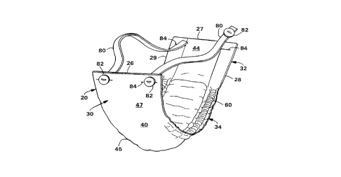
10In general, the undergarment 20 includes elasticized bumpers 60
disposed in each of the side margins 38 of the undergarment. In one
embodiment, each elasticized bumper 60 includes an internal barrier
structure 62 bonded to the side margin 38 and an elasticized cover 64
disposed over the internal barrier structure. In one embodiment, the cover
64 may be formed of a hydrophobic material to retard the spread of liquid
toward the side edges 28 and 29 of the undergarment 20. In another
embodiment, the elasticized cover 64 includes lateral portions 74 that are
bonded to the side margins 38, leaving the elasticized cover not directly
adhered to the internal barrier structure 62. This permits the elasticized
cover 64 to move relative to the internal barrier structure 62 and decreases
the formation of large rugosities which would otherwise be caused by
gathering of the internal barrier structure. In yet another particular
embodiment, the elasticized cover 64 may include at least one casing layer
65 and at least 4 elastic strands 66 operatively joined to the casing layer.
The elastic strands 66 are arranged generally parallel to one another and
within about 8 millimeters of neighboring strands to improve uniform
gathering of the cover 64 and again minimize the formation of rugosities.
In an alternative embodiment, an elasticized bumper 202 includes an
elasticized cover 64 that fully encircles the internal barrier structure 62.
The illustrated undergarment 20 defines a longitudinal axis or center
line and a transverse axis or center line, represented by arrows 22 and 24
in Fig. 2. The undergarment 20 has opposite, front and back longitudinal
end edges 26 and 27, and first and second longitudinal side edges Z8 and 29
that extend between the longitudinal end edges. The undergarment 20
includes a first or front waist region 30, a second or back waist region 32,
and an intermediate, crotch region 34 positioned between and interconnecting
the front and back waist regions. The outer edges of the undergarment 20
g
CA 02221140 1997-12-02
WO 9~/4D C ' D PCT~US96/0~0~5
define a periphery 36 in which the longitudinally extending side margins are
designated 38 and the laterally extending end margins are designated 39.
The end edges Z6 and 27 and side edges 28 and 29 are shown as generally
straight, but optionally, may be curvilinear and contoured.
The front waist region 30 is contiguous with the front end edge 26 and
extends longitudinally inward therefrom toward the transverse center line
24 of the undergarment 20. The back waist region 32 is contiguous with the
back end edge 27 and extends longitudinally inward therefrom toward the
transverse center line 24. The waist regions 30 and 32 comprise those upper
portions of undergarment 20 which, when worn, wholly or partially cover or
encircle the waist or mid-lower torso of the wearer. The intermediate,
crotch region 34 comprises that portion of undergarment 20 which, when worn,
is positioned between the legs of the wearer and covers the lower torso of
15 the wearer. Thus, the crotch region 34 is the area where insults of urine
typically occur in the undergarment or other disposable absorbent article.
The undergarment 20 includes a substantially liquid impermeable
moisture barrier 40, an absorbent structure 42 ~Figs. 2 and 3) disposed on
20 the moisture barrier, and a substantially liquid permeable bodyside liner
44 bonded to the moisture barrier to sandwich the absorbent structure
therebetween. The moisture barrier 40 and bodyside liner 44 are desirably
longer and wider than the absorbent structure 42 so that the peripheries of
the moisture barrier and bodyside liner may be bonded together using
25 ultrasonic bonds, thermal bonds, adhesives, or other suitable means. The
periphery of the moisture barrier 40, the bodyside liner 44, or the
peripheries of both, typically form the side and end margins 38 and 39 of
the undergarment 20. The absorbent structure 42 may also be bonded to the
moisture barrier 40 and/or the bodyside liner 44 using ultrasonic bonds,
30 thermal bonds, adhesives, or other suitable means.
The moisture barrier 40 desirably comprises a material that is formed
or treated to be liquid impermeable. Alternatively, the moisture barrier 40
may comprise a liquid permeable material and other suitable means (not r
35 shown), such as a liquid impermeable layer associated with the absorbent
structure 42, may be provided to impede liquid movement away from the
absorbent structure. The moisture barrier 40 rnay also be gas permeable,
such that gases encountered during use of the absorbent article are able to
- 10 -
CA 02221140 1997-12-02
W O 96/40030 PCTAJS~6/090~
pass through the material under ordinary use conditions, over either all or
part of its surface area.
The moisture barrier 40 may comprise a single layer of material or a
laminate of two or more separate layers of material. Suitable moisture
barrier materials include films, wovens, nonwovens, laminates of films,
wovens, and/or nonwovens, or the like. For example, the moisture barrier 40
may comprise a thin, substantially liquid impermeable web or sheet of
plastic film such as polyethylene, polypropylene, polyvinyl chloride or
similar material. The moisture barrier material may be transparent or
opaque and have an embossed or matte surface. One particular material for
the moisture barrier 40 is a polyethylene film that has a nominal thickness
of about 0.025 millimeter and a systematic matte embossed pattern, and that
has been corona treated on both sides. Another suitable moisture barrier
material is an adhesive or thermal laminate comprising a cast or blown film
formed of polypropylene, polyethylene or the like, and a spunbond web formed
of polypropylene and polyethylene medium-crimped bicomponent fibers in a
50/50 side-by-side configuration.
The absorbent structure 42 comprises materials adapted to absorb and
retain liquid waste. The absorbent structure 42 may comprise various
absorbent materials, such as an air-formed batt of cellulosic fibers such
as wood pulp fluff or a coform material composed of a mixture of cellulosic
fibers and synthetic polymer fibers. Polymer fibers may be incorporated,
Z5 for example, in the manner described in U.S. Patent 5,2Z7,107 issued
July 13, 1993, to Dickenson et al. The absorbent structure 42 may also
include compounds to increase its absorbency, such as O - 95 weight percent
of organic or inorganic high-absorbency materials, which are typically
capable of absorbing at least about 15 and desirably more than 25 times
their weight in water. Suitable high-absorbency materials are described in
U.S. Patents 4,699,823 issued October 13, 1987, to Kellenberger et al. and
5,147,343 issued September 15, 1992, to Kellenberger, which are incorporated
herein by reference. High-absorbency materials are available from various
- commercial vendors, such as Dow Chemical Company, Hoechst Celanese
Corporation, and Allied Colloids, Inc. The absorbent structure 42 may also
- include tissue layers or acquisition or distribution layers to help maintain
the integrity of fibrous absorbents or transport liquids (not shown).
-- 11 --
CA 02221140 1997-12-02
WO 96/40030 PCT~US~ 5
In the ;llustrated embodiment, the moisture barrier 40 extends the
full length and width of the undergarment 20 and thus defines in part the
front and back end edges 26 and Z7 and the first and second side edges 28
and 29. As best shown in Fig. 2, the absorbent structure 42 has opposite
end edges 45 and opposite side edges 46 that extend between the end edges.
The end and side edges 45 and 46 of the absorbent structure 42 are desirably
spaced inward from the end edges 26 and 27 and side edges 28 and 29 of the
undergarment 20. In the longitudinal direction, for example, the absorbent
structure 42 desirably has a length of from about 50 to about 95 percent of
the undergarment 20. The bodyside liner 44 also includes opposite end edges
48 and opposite side edges 49 that extend between the end edges. In the
illustrated embodiment, the end edges 48 extend to the full length of the
undergarment 20, although the side edges 49 are spaced inward from the side
edges 28 and 29 of the undergarment. Alternatively, of course, the side
edges 49 of the bodyside liner 44 could extend to or independently form the
side edges 28 and 29 of the undergarment 20.
As best shown in Fig. 3, the undergarment 20 desirably includes a
carrier sheet 50 disposed between the absorbent structure 42 and the
moisture barrier 40. The carrier sheet 50 may serve as a carrier web for
the absorbent structure 42 during high speed manufacturing processes to
manufacture the undergarment 20. The carrier sheet 50 desirably comprises
a hydrophilic, air and liquid permeable material such as a high wet strength
tissue. For example, the carrier sheet 50 may comprise a 17 grams per
square meter (gsm) web of cellulose fibers. ~lternatively, the carrier
sheet 50 may comprise nonwettable nonwoven webs formed of polyolefins,
polyesters, rayon or the like, desirably with relatively low basis weights,
such as less than about 30 gsm, and with sufficient mechanical strength to
withstand handling in a high-speed manufacturing process, a film, or the
like. The carrier sheet 50 has opposite end edges 51 and opposite side
edges 52 that extend between the end edges. The end edges 51 of the carrier
sheet 50 may be coextensive with the end edges 45 of the absorbent structure
42. ~he width of the carrier sheet 50 is desirably such that the side edges
52 extend transversely outward of the absorbent structure 42 into the side
margins 38 of the undergarment 20.
The illustrated undergarment 20 also includes a liquid handling layer
54 that is disposed between the bodyside liner 44 and the absorbent
- 12 -
CA 02221140 1997-12-02
W O 96/40030 PCTrUS~610901S
structure 42. The liquid handling layer 54 has opposite end edges 55 and
opposite side edges 56 that extend between the end edges. Desirably, but
not necessarily, the length of the liquid handling layer 54 is such that the
end edges 55 are coextensive with the end edges 26 and 27 of the
undergarment 20. Thus, the liquid handling layer 54 is positioned in the
front and back waist sections 30 and 32 between the absorbent structure 42
and the end edges 26 and 27 of the undergarment 20. The width of the liquid
handling layer 54 is suitably such that the side edges 56 are positioned
between the side edges 46 of the absorbent structure 42 and the side edges
28 and 29 of the undergarment 20.
The liquid handling layer 54 is desirably present in the front and
back wa;st sections 30 and 32 to draw liquid that may be present in those
regions away from the interior surface of the undergarment 20 and thus away
from the skin of a wearer. The liquid handling layer 54 may comprise an
absorbent material such as one or more cellulose tissue sheets or an airlaid
web of hydrophilic fibers. Alternatively, the liquid handling layer 54 may
comprise a material adapted to rapidly take in and/or distribute liquids.
Any woven or nonwoven web adapted to quickly take in and/or transport
liquids may be suitable for the liquid handling layer 54. For example, the
liquid handling layer 54 may comprise a nonwoven web such as a spunbonded,
meltblown or bonded-carded web composed of synthetic polymer filaments or
fibers such as polypropylene, polyethylene, polyesters or the like or a web
of natural polymer filaments or fibers as rayon or cotton. The liquid
handling layer 54 desirably comprises a material that is formed or treated
to be substantially hydrophilic. Examples of suitable materials are also
described in U.S. Patent 5,192,606 issued March 9, 1993, to D. Proxmire et
al.; U.S. Patent 4,798,603 issued January 17, 1989, to S. Meyer et al.; U.S.
Patent 5,364,382 issued November 15, 1994, to M. Latimer et al.; U.S. Patent
Application Ser. No. 757,760 of W. Hanson et al. filed September 11, 1991
(Attorney docket No. 9922); U.S. Patent Application Ser. No. 206,986 of
C. Ellis and D. Bishop, entitled FIBROUS NONWOVEN WEB SURGE LAYER FOR
PERSONAL CARE ABSORBENT ARTICLES AND THE LIKE, and filed March 4, 1994
(Attorney docket No. 11,256); and U.S. Patent Application Ser. No. 206,069
of C. Ellis and R. Everett, entitled IMPROVED SURGE MANAGEMENT FIBROUS
NONWOVEN WEB FOR PERSONAL CARE ABSORBENT ARTICLES AND THE LIKE, and filed
March 4, 1994 (Attorney docket No. 11,387); the disclosures of which are
hereby incorporated by reference.
- 13 -
CA 02221140 1997-12-02
WO ~ 003n PCTAUS~6/0~0~5
In the lllustrated embod~ment, the carrier ~;heet 50 ~s disposed between
the moisture barrier 40 and the absorbent structure 42. Alternatively, the
carrier sheet 50 may be disposed between the absorbent structure 42 and the
bodyside liner 44. In such case, the carrier sheet 50 should be liquid
permeable and may function as the liquid handling layer 54. Further, the
liquid handling layer 54 may be disposed between the absorbent structure 42
and the moisture barrier 40.
The bodyside liner 44 is formed of a liquid permeable material so that
liqu;d waste, and possibly semi-solid waste as well, can pass through the
liner and be absorbed by the absorbent structure 42. Suitable bodyside
liners 44 may comprise a nonwoven web or sheet of wet strength tissue paper,
a spunbonded, meltblown or bonded-carded web cornposed of synthetic polymer
filaments or fibers, such as polypropylene, polyethylene, polyesters or the
like, or a web of natural polymer filaments or fibers such as rayon or
cotton. In addition, the bodyside liner 44 is desirably nonelastic and may
be treated with a surfactant to aid in liquid transfer. In a particular
embodiment of the invention, the liner 44 comprises a nonwoven, spunbond
polypropylene fabric composed of about 2.8-3.2 denier fibers formed into a
web having a basis weight of about 22 gsm and density of about 0.06 gm/cc.
The fabric is surface treated with about 0.28 weight percent of a surfactant
commercially available from Union Carbide Chemicals and Plastics Company,
Inc., of Danbury, Connecticut, U.S.A. under the trade designation Triton
X-102.
The undergarment 20, portions of which are in a stretched and laid
flat condition in Fig. 2, is illustrated as having a rectangular periphery
36. Of course, the undergarment 20 may optionally be hourglass-shaped, I-
shaped, T-shaped, or irregularly-shaped. The gereral shape of the absorbent
structure 42 may correspond to the shape of the undergarment 20 or assume
a different shape.
To conform the side margins 38 of the undergarment 20 to the body of
the wearer and minimize the likelihood of leakage from the side edges 28
and 29, the undergarment is provided with an elasticized bumper 60 in each
side margin 38. The elasticized bumpers 60 are disposed on the moisture
barrier 40 at least in the crotch region 34, but; they may also extend into
- 14 -
CA 02221140 1997-12-02
WO 96/40030 PCTAUS96/09045
the front and back waist regions 30 and 32. lhe elasticized bumpers 60 may
be generally straight or curved and may but need not follow the peripheral
shape of either the side edges 46 of the absorbent structure 42 or the side
edges 28 and 29 of the undergarment 20. In one alternative embodiment, the
elasticized bumpers 60 may be positioned in one or both of the waist regions
30 and 32, such as in end margins 39, oriented parallel to the transverse
axis 24 instead of or in addition to being positioned along the side edges
28 and 29 (not shown).
10In the embodiment shown in Figs. 1-3, the elasticized bumpers 60
comprise an internal barrier structure 62 disposed on the moisture barrier
40 and a cover 64 disposed over the internal barrier structure. The
illustrated cover 64 includes a pair of casing layers 65 and a plurality of
strands 66 of elastic positioned between and operatively joined to the
casing layers (Fig. 3). Alternatively, the cover 64 may comprise a single
elastomeric fabric or a composite of a single casing layer and one or more
elastomeric elements or layers (not shown).
The internal barrier structures 62 of the undergarment 20 shown in
Figs. 1-3 are oriented parallel to the longitudinal axis 22 and positioned
between the side edges 46 of the absorbent structure 42 and the side edges
28 and 29 of the undergarment. In particular, the internal barrier
structures 62 are suitably spaced from the side edges 46 of the absorbent
structure 42 by from 0 to about 7 centimeters (cm), and particularly from
25about 0.5 to about 3 cm. Also, the internal barrier structures 62 are
suitably positioned from about 0.5 to about 4 cm from the side edges 28 and
29, such as from about 1 to about 3 cm from the side edges. The length of
the internal barrier structures 62 is suitably comparable to the length of
the crotch region 34 but may be up to the full length of the undergarment
20. For convenience of manufacturing though, as discussed in greater detail
below, the length of the internal barrier structures 62 is desirably the
same as the length of the absorbent structure 42.
- In the illustrated embodiment, the internal barrier structures 62 are
positioned transversely inward from the side edges 52 of the carrier sheet
50. A bead 68 of adhesive or other suitable means is used to bond the
internal barrier structures 62 to the carrier sheet 50 (Fig. 3). The
adhesive bead 68 may also be effective to penetrate through the carrier
- 15 -
CA 0222ll40 l997-l2-02
WO 9~/10~'~ PCT~US9G/09C15
sheet 50 and bond the carrier sheet to the moisture barrier 40. Desirably,
the adhesive bead 68 is continuous along the lenyth of the internal barrier
structure 62 and does not allow liquid to penetrate between the internal
barrier structure and the moisture barrier 40.
The internal barrier structures 62 desirably function to elevate the
elasticized bumpers 60 from the plane of the undergarment 20 defined by the
longitudinal and transverse axes 22 and 24. In particular, the elasticized
bumpers 60 suitably have a height dimension measured from the plane of the
10moisture barrier 40 of from about 3 to about 25 millimeters (mm), and
particularly from about 5 to about 15 mm. The width of the elasticized
bumpers 60 is desirably from about 2 to about 30 mm, and more particularly,
from about 5 to about 15 mm, for improved performance.
15The internal barrier structures 62 may be formed of any material which
allows the elasticized bumpers 62 to conform to the shape of the wearer.
In one particular embodiment, the internal barrier structures 62 comprise
a resilient sliver structure formed of 100 percent 2.2 denier hydrophobic
polypropylene staple fibers having a length of 3.8 cm and available from
Hercules Inc. of Wilmington, Delaware, U.S.A., under the trade designation
T190. The term "sliver" refers generally to a continuous untwisted strand
or bundle of flat fibers produced by a conventional carding process.
Carding separates fibers from each other, lays them parallel, forms them
into a thin web, and then condenses them into the sliver. The process for
25forming the sliver structure is disclosed in U.S. Patent 5,133,371 issued
July 28, 1992, to Sivess, which is incorporated herein by reference.
The sliver structure may be composed of a wide variety of cardable
fibers, but is desirably comprised of those fibers which are substantially
nonabsorbent, nonelastomeric and hydrophobic in nature. The internal
barrier structures 62 may also be hydrophilic, particularly in instances
where the cover 64 is formed or treated to be hydrophobic. The internal
barrier structures 62 may comprise additional components to enhance the
resiliency of the structures, such as foams or resilient fibers. Ends 69
of the side barrier structures 62 are desirably but not necessarily
coextensive with the ends 51 of carrier sheet 50 and the ends 45 of the
absorbent structure 42.
- 16 -
CA 02221140 1997-12-02
WO ~/40~3~ PCTrUS~6/03C~S
The cover 64 is formed of an elastomeric material or composite adapted
to gather the side margins 38 of the undergarment 20 and maintain the
elasticized bumpers 60 against the skin of the wearer. The cover 64
includes opposite longitudinal ends 70 and opposite longitudinal sides 71
- 5 extending between the ends. The ends 70 of the cover 64 in the illustrated
embodiment are coextensive with the end edges 26 and 27 of the undergarment
20, and one side edge 71 of each cover 64 is desirably coextensive with or
adjacent to a side edge 28 or 29 of the undergarment.
With particular reference to Fig. 3, the covers 64 also include
opposite lateral portions 74 with a central portion 75 positioned between
and interconnecting the lateral portions. The lateral portions 74 are
contiguous with the side edges 71 of the covers 64. The covers 64 are
disposed on the internal barrier structures 62 and have sufficient width
such that the lateral portions 74 can be bonded to the moisture barrier 40
with beads 72 of adhesive or other suitable means. As illustrated, the
adhesive beads 72 nearest the side edges 28 and 29 directly bond the covers
64 to the moisture barrier 40, while the adhesive beads 72 nearest the
absorbent structure 42 directly bond the covers 64 to the carrier sheet 50
and are desirably effective to penetrate through the carrier sheet and bond
the carrier sheet to the moisture barrier. Both adhesive beads 72 are
desirably continuous along the length of the covers 64 and do not allow
liquid to penetrate between the covers and the moisture barrier 40.
Notably, the central portions 75 of the covers 64 are desirably not bonded
directly to the internal barrier structures 62. Rather, the inner surfaces
of the covers 64 are free to slide over the exterior surfaces of the
internal barrier structure 62 to minimize the formation of rugosities.
The casing layers 65 desirably define the end and side edges 70 and
71 of the cover 64. The casing layers 65 may be formed of any flexible,
gatherable material. In particular embodiments, the casing layers 65 are
either impermeable to liquids or formed or treated to be hydrophobic. Less
desirably, the casing layers 65 may be hydrophilic or liquid permeable and
the internal barrier structures 6Z are formed of a hydrophobic material.
One particular material that may be useful in forming the casing layer 65
is a thermally point bonded web of bicomponent spunbond fibers having a
basis weight of from about 10 to about 27 gsm (0.3-0.8 osy), such as from
about 12 to about 20 gsm (0.4-0.6). The fibers are 50/50 side-by-side
- 17 -
-
CA 02221140 1997-12-02
W 096/40030 PCTrUS961'0~1S
polypropylene/polyethylene bicomponent fibers constructed of polyethylene
available from Dow Chemical Company of Midland, Michigan, U.S.A., under the
trade designation ASPUN~ 6811A and polypropylene available from Exxon
Chemical Company of Houston, Texas, U.S.A., under the trade designation
PP3445. The extruded fibers suitably have an average fiber diameter of
between about 17 and 25 microns, such as about Z3 microns, and a low crimp,
such as approximately one or fewer crimps per extended inch using ASTM test
method D-3937-82. The web may be produced according to the processes for
production of bicomponent webs as described in U.S. Patent 5,382,400 issued
January 17, 1995, to Pike et al., the disclosure of which is incorporated
herein by reference. Other suitable materials for use as the casing layer
include copolymer, polypropylene, polyester or nylon spunbonds,
combinations of these polymers in bicomponent constructions or in blends,
and carded webs composed of suitable cardable fibers. The fibers may have
varying degrees of crimp; however, the crimp is desirably less than
approximately 15 or fewer crimps per extended inch. Also, the webs may be
bonded by other suitable means such as through air bonding.
The cover 64 may alternat1vely comprise only a single casing layer 65
with the elastic strands 66 bonded to the single casing layer on the surface
facing the internal barrier structure 62. Still alternatively, the cover
64 may be composed of a substantially elastomeric layer, such as polymer
films, woven fabrics, nonwoven fabrics or the like, as well as combinations
thereof, rather than a plurality of strands of elastomeric material. For
example, the cover 64 can be composed of a stretch-bonded-laminate (SBL)
material, a neck-bonded-laminate (NBL) material, an elastomeric film, an
elastomeric foam material, or the like. For example, suitable meltblown
elastomeric fibrous webs for forming the cover 64 are described in U.S.
Patent 4,663,220 issued May 5, 1987 to T. Wisneski et al., the disclosure
of which is hereby incorporated by reference. Examples of composite fabrics
comprising at least one layer of nonwoven textile fabric secured to a
fibrous elastic layer are described in European Patent Application EP No. O
110 010 published on April 8, 1987 with the inventors listed as J. Taylor
et al., the disclosure of which is hereby incorporated by reference.
Examples of NBL materials are described in U.S. Patent 5,226,992 issued
July 13, 1993 to Morman; U.S. Patent 5,336,545 issued August 9, 1994 to
Morman; and U.S. Patent Application Serial No. 08/276,924 by Haffner et al.,
f;led July 19, 1994, and titled "COMPOSITE ELASTIC NECK-BONDED MATERIAL"
- 18 -
CA 02221140 1997-12-02
W O 96/40030 PCTAJ59U~O~IS
(Attorney Docket No. 8704.4); the disclosures of which are hereby
incorporated by reference.
In the illustrated embodiment, elastic strands 66 are disposed between
the casing layers 65 and operatively joined thereto using adhesives or other
suitable means (Fig. 3). For example, the elastic strands 66 may be
adhesively bonded to the casing layers 65 using a 5 gsm application of a hot
melt, rubber-based adhesive available from Findley Adhesives of Wauwatosa,
Wisconsin, U.S.A., under the trade designation H-2096. The elastomeric
component of the adhesive is available from the Shell Chemical Company of
Houston, Texas, U.S.A., under the trade designation KRATON. The elastic
strands 66 may be formed of a dry-spun coalesced multi-filament elastomeric
thread sold under the trade name LYCRA~ and available from E.I. Du Pont de
Nemours and Company. Alternat;vely, the elastic component of the cover 64
may comprise other typical elastics utilized in the undergarment-making art,
such as a thin ribbon of natural or synthetic rubber, a stretch bonded
laminate material, other strand structures such as isoprene strands
available from JPS Elastomerics, Stuart, Virginia, U.S.A., elastomeric films
such as EVA or urethane films, hot melt elastomeric adhesives, or the like.
The number, spacing, positioning, power and overall tension of the
elastic strands 66 are desirably controlled to maintain the elasticized
bumpers 60 against the body of the wearer and create a physical barrier to
lateral liquid flow, while at the same time minimizing the formation of
rugosities which could create leakage sites. In particular embodiments, the
covers 64 comprise at least 4 elastic strands 66, and particularly from 4
to 12 elastic strands, and more particularly from 6 to 8 elastic strands.
The elastic strands 66 are spaced from neighboring strands by less than
about 8 mm, and particularly by from about 3 to about 6 mm from neighboring
strands for improved performance. The elastic strands 66 are suitably
spaced from the adhesive beads 72 so the elastlc characteristics of the
strands are not defeated. The individual elastic strands 66 may be
identical to one another. Alternatively, however, at least one of the
- elastic strands 66 has greater elastic power than at least one of the other
elastic strands 66. Further, the elastic strands 66 having greater elastic
- power are desirably located on top of the interior barrier structures 62,
which corresponds to the central portion 75 of the cover 64. In the
illustrated embodiment (Fig. 3), for example, the cover 64 includes 7
- 19 -
CA 02221140 1997-12-02
W O 96/40030 PCTrUS96~ G1S
elastic strands 66, and 3 of those strands desirably have greater elastic
power than the rema~ning 4 strands. The 3 strands of greater elastic power
are desirably centrally located between the adhesive beads 72 that bond the
cover 64 to the side margins 38. This configuration has the benefit of
positioning the elastic strands 66 with greater elastic power closer to the
body of the wearer. As a result, the undergarment 200 tends to more easily
assume a "U" shape as viewed in the longitudinal direction 22. The "U"
shape is best suited to conform to the body of the wearer and aid in
formation of a leakage barrier.
The term elastic power is used herein to mean the retraction force of
one elastic member compared to the retraction force of another elastic
member. One elastic member may have more elastic power than another member
due to the nature of the materials of which they are made, the levels of
elongation of the elastic members, the decitex of elastic members, or the
like. By way of illustration, a cover 64 may incorporate one set of elastic
strands 66 having a decitex of 620 and another set of elastic strands having
a decitex of 940. Both sets of strands may be stretched to 270 percent
elongation and bonded to the casing layer 65. The set of 940 decitex
strands could be positioned in the central portion 75 of the cover 64 and
the set of 620 decitex strands could be positioned in the lateral portions
74 of the cover.
The elasticized bumpers 60 of the present invention desirably provide
relatively high degrees of tension without creating localized regions of
high tension that contribute to skin irritation In particular, the side
margins 38 of the undergarment 20 desirably possess a side margin tension
of from about 0.06 to about 0.30 kilograms. One suitable procedure for
determining the side margin tension of an absorbent article is the Product
Tension Test set forth in the Test Methods section below.
The attachment system in the lllustrated embodiment includes a pair
of strap members 80 and fastening components to releasably attach the strap
members to the front and back waist regions 30 and 32 (Fig. 1). The
fastening components include a retainer 82 in the form of a button bonded
at each end of each strap member 80. The retainers 82 may be releasably
secured in slits 84 formed near the corners of the undergarment 20 in the
moisture barrier 40 and other components. When the undergarment 20 is
- 20 -
CA 0222ll40 l997-l2-02
WO 96/40030 PCTAJS~GI~5C15
positioned on the wearer, the straps 80 extend between the front and back
slits 84 so that the retainers 82 may be releasably secured in the slits.
Optionally, other types of attachment systems, such as tapes, stretchable
side panels, self-engaging geometric shaped materials, such as hooks, loops,
bulbs, mushrooms, arrowheads, balls on stems, or the like, may be employed.
The illustrated attachment system as well as alternatives thereto are
described in U.S. Patent 4,315,508 issued February 16, 1982, to Bolick and
U.S. Patent 5,386,595 issued February 7, 1995, to Kuen et al., the
disclosures of which are incorporated herein by reference.
The strap members 80 (Fig. 1) are each generally rectangular strips
of material, which material is desirably an elastic material capable of
stretching to approximately 2.8 to 3 times its relaxed length. The strap
members 80 desirably have a length from about 15 to about 41 centimeters
(cm.), and a width from about 1 to about 5 cm. For example, each strap
member 80 may be 28 cm. long and 2.5 cm. wide. The cut ends of the strap
members 80 may be bonded by ultrasonics, adhesives or other suitable means
to prevent raveling.
In use, the undergarment 20 is positioned on the wearer and secured
with the attachment system. The function of the elasticized bumpers 60
includes both gathering the undergarment 20 in the longitudinal direction
22 to conform the garment to the body as well as presenting a raised
physical barrier to impede the lateral movement of liquids. In this regard,
the elasticized bumpers 60 and in particular the covers 64 are formed of
materials that resist liquid movement in the transverse direction. In
particular embodiments, the covers 64 are desirably unadhered to the
underlying internal barrier structures 62 to minimize the formation of large
rugosities along the length of the elasticized bumpers. Also in particular
embodiments, the elasticized bumpers 60 are constructed of individual
elastic strands 66 and the number and spacing of the strands is selected so
as to minimize the formation of small rugosities along the surface of the
elasticized bumpers. Both large and small rugosities would otherwise create
sites where liquid could escape past an elasticized physical barrier.
A particularly efficient method for constructing the undergarment 20
described in relation to Figs. 1-3 is schematically illustrated in Fig. 4.
The method includes a number of continuous processes and does not involve
- 21 -
CA 02221140 1997-12-02
W O 96/40030 PCTAJS96/09045
any cut-and-place operations. In particular, the method includes providing
a continuous carrier tissue web 100 from a forming or unwind source 101,
and providing a ~ontinuous absorbent web 102 from an absorbent web source.
For example, the absorbent web 102 may be supplied from a forming drum 104,
as is well known in the art. The absorbent web 102 is disposed on the
carrier web 100 and both are advanced in the direction of arrow 106 via
transport means 108, such as a belted conveyor system or other suitable
means. The absorbent web 102 is desirably narrower than the carrier web 100
and centered between the side edges 52 (Figs. 2 and 3) of the carrier web.
The carrier and absorbent webs 100 and 10Z are routed past adhesive
station 110 where beads 68 of adhesive are applied to the carrier web
outward of the side edges 46 (Figs. 2 and 3) of the absorbent web. The
carrier and absorbent webs 100 and 102 continue to be advanced in the
direction of arrow 106 via transport means 112. A pair of continuous
strands 114 of material for forming the internal barrier structures 62 of
the undergarment 20 are provided from a forming or unwind source 115. The
strands 114 of internal barrier material are routed past roller 116 and
united with the carrier web 100 at the locatior of the adhesive beads 68
such that the strands 114 are bonded to the carrier web outward of the side
edges 46 of the absorbent web 102.
The continuous carrier web 100, the continuous absorbent web 102, and
the continuous strands 114 of internal barrier material together form a
continuous in-process composite structure 120, which is transported to an
optional de-bulking unit 122 which functions to shape the absorbent web 102.
It will be apparent that the continuous strands 114 of internal barrier
material may be bonded to the continuous carrier web 100 either prior to or
after the de-bulking unit 122.
The composite structure 120 is then conveyed by transport means 126 to
a web cutting mechanism 128, shown for purposes of illustration as a
rotating shear. The cutting mechanism 128 transversely cuts the continuous
composite structure 120 into individual, in-process composite structures
130. Each composite structure 130 comprises a carrier sheet 50, an
absorbent structure 42, and a pair of internal barrier structures 62
(Figs. 2 and 3). The carrier sheet 50 has opposite end edges 51 and
opposite side edges 52. The absorbent structure 42 has opposite end edges
- 22 -
CA 0222ll40 l997-l2-02
WO 96/40030 PCTAJS96/o~c15
45 coterminous with end edges 51 of the carrier sheet 50 and opposite side
edges 46 spaced inward from the side edges 52 of the carrier sheet. The
internal barrier structures 62 are positioned between the side edges 46 of
the absorbent structure 42 and the side edges 52 of the carrier sheet 50 and
have opposite ends 69 coterminous with the end edges 51 of the carrier
sheet. The individual composite structures 130 exit the cutting mechanism
128 onto transport means 132 which is travelling at a speed greater than
that of transport means 126. As a result, the individual composite
structures 130 become spaced from one another.
A continuous web 140 of moisture barrier material is provided from a
forming or unwind source 142 and transported in the direction of arrow 144.
Adhesive beads 72 are provided from an adhesive source 146 and disposed on
the continuous moisture barrier web 140. Traditional leg elastics may also
be bonded to the moisture barrier web 140 if desired (not shown). The
moisture barrier web 140 is routed past roll 148 to an assembly station 149.
Simultaneously, a continuous web 150 of bodyside liner material is
provided from a forming or unwind source 152 and transported in the
direction of arrow 154. Adhesive 156 may optionally be applied to the
continuous bodyside liner web 150 from an adhesive source 158. A continuous
web 160 of a liquid handling material is provided from a forming or unwind
source 162, routed over transport roll 164 and united with the continuous
bodyside liner web 150 at another transport roll 166. The combined bodyside
liner web 150 and liquid handling web 160 continue to be transported in the
direction of arrow 154 past transport roll 168.
Two covers 64 are constructed and disposed over the internal barrier
structures 62, although the method and apparatus for forming only one of the
covers appears in Fig. 4. Each cover 64 may be constructed from a pair of
continuous casing webs 170 and 172 provided from forming or unwind sources
174 and 176. Elastic strands 66 are provided from an elastic forming or
unwind source 178 and operatively joined to the casing webs 170 and 17Z with
~ adhesive 180 from an adhesive source 182. The adhesive 180 may be applied
over the elongated elastic strands 66 just prior to the strands coming into
- contact with one of the casing webs 170, as disclosed in U.S. Patent4,842,666 issued June 27, 1989, to Werenicz. The adhesive 180 is desirably
applied intermittently and timed to bond the elastic strands 66 to the
- 23 -
CA 02221140 1997-12-02
WO 96/40030 PCTAUS96/09045
casing webs 170 and 172 at locations corresponding to the position of the
internal barrier structures 62. Alternatively, the adhesive 180 may be
applied continuously to the cover 64, or applied continuously and diverted
over a portion of the length of the cover using a diverting mechanism such
as the air diverting system disclosed in U.S. Patent 4,711,683 issued
December 8, 1987, to Merkatoris.
The casing webs 170 and 172 with the elastic strands 66 bonded thereto
are then routed past a transport roll 184 ancl united with the bodyside
liner web 150 and the liquid handling web 160, and all of these components
are transported to the assembly station 149. It will be apparent that the
components can be arranged so that the covers 64 are at least partially on
top of the bodyside liner web 50 as illustrated, or alternatively positioned
beneath the bodyside liner web (not shown).
The components of the undergarment 20 are united and bonded together
at the assembly station 149. The individual composite structures 130 are
introduced between the moisture barrier web 140 and the bodyside liner web
150. The position of the covers 64 is controlled to coincide with the
position of the internal barrier structures 62. The elastic strands 66 may
be disposed directly over the internal barrier structures 62.
Alternatively, however, the position of the covers 64 and/or the elastic
strands 66 may be controlled to concentrate t.he elastic strands either
transversely inward or transversely outward of the internal barrier
structures 62. The adhesive beads 72 function to bond the covers 64 to the
moisture barrier, and other construction adhesives (not shown) may be used
to bond other components together.
From the assembly station 149, the components are carried by a
transport means 186 to a cutting mechanism 188 which transversely cuts the
continuous components to form individual undergarments 20. The cutting
mechanism 188, for example a rotary shear, is timed to cut between the
individual composite structures 130 and thus sever the moisture barrier web
140, the bodyside liner web 150, the liquid handling web 160, the casing
webs 170 and 172, and the elastic strands 66. Desirably, the cutting
mechanism 188 severs the covers 64 at locations where the adhesive 180 has
been interrupted or diverted and does not bond the elastic strands 66 to the
casing layers 65. As a result, the portions of the elastic strands 66
- 24 -
CA 0222ll40 l997-l2-02
WO 96/40030 PCTrUS96~
adjacent the ends 26 and 27 of the undergarment 20 are free to snap back to
the location of the adhesive 180, such as over the internal barrier
structures 62. The longitudinal position of the adhesive 180 and thus the
longitudinal position of the elastic strands 66 can thereby be controlled
independently of the longitudinal position of the internal barrier
structures 62. In a particularly desirably embodiment, the elastic strands
66 are attached to the casing layers 65 so that the effective ends of the
strands are located from about 1 to about 5 cm longitudinally outward of
each end 69 of the side barrier structures 62. Alternatively, the elastic
strands 66 may be attached to the casing layers 65 over the full length of
the undergarment 20.
The method shown in Fig. 4 of making an undergarment is particularly
desirable because all of the component webs are continuously supplied to the
assembly process. Advantageously, this eliminates the need to separately
cut, place and register an individual component of the elasticized bumpers
60. Additionally, the length of the internal barrier structures 62 is
mechanically associated with the length of the absorbent structure 42.
Also, the ends 69 of the internal barrier structures 62 are conveniently
contained beneath the elasticized covers 64. Further, the method allows the
longitudinal and transverse position of the elastic strands 66 to be
controlled independently of the position of the internal barrier structures
62.
An alternative embodiment is illustrated by an undergarment 200 shown
in Figs. 5 and 6. Components similar to those previously described have
been given the same reference numeral. The undergarment 200 includes an
elasticized bumper 202 disposed on each side margin 38 of the undergarment.
The elasticized bumpers 202 desirably extend in the longitudinal direction
22 at least as far as the ends 45 of the absorbent structures 42, and may
extend beyond the ends 45 up to and including to the end edges 26 and 27 of
the undergarment 200.
Each elasticized bumper 202 includes an internal barrier structure 62
and an elasticized cover 64. The cover 64 fully encircles the internal
- barrier structure 62 in the transverse direction 24, as illustrated in
Fig. 6. The side edges 71 of the cover 64 overlap one another and are
bonded together using adhesives, ultrasonic bonds, thermal bonds, mechanical
- 25 -
CA 0222ll40 l997-l2-02
WO 96/40030 PCTAUS96~'~5015
bonds or other suitable means. The longitudinal ends 70 of the cover 64 may
be coextensive with the ends 69 of the internal barrier structure 62, and
the ends 70 and 69 may be crimped and bonded together by adhesives or other
suitable means.
Each cover 64 is operatively joined to one of the side margins 38 by
a bead 204 of adhesive. The adhesive bead 204 clesirably is of sufficient
size to penetrate through the bodyside liner 44 and is continuous along the
length of the elasticized bumper 202 so that liquid cannot penetrate between
the bumper and the moisture barrier 40. The covers 64 may alternatively be
bonded to the side margins 38 by ultrasonic bonds, thermal bonds, mechanical
bonds or other suitable means.
The illustrated cover 64 includes a pair of casing layers 65 and a
plurality of elastic strands 66 positioned between and operatively joined
to the casing layers. In one particular embodiment, the cover 64 includes
at least 4 generally parallel elastic strands spaced generally evenly
between the side edges 71 of the cover. More desirably, though, the cover
64 includes at least 6 elastic strands 66, such as the 7 strands shown in
Fig. 6. The elastic strands 66 are desirably spaced from neighboring
strands by less than about 8 mm, and particularly by from about 3 to about
6 mm from neighboring strands for improved performance.
The individual elastic strands 66 may be identical to one another.
Alternatively, however, at least one of the elastic strands 66 has greater
elastic power than at least one of the other elastic strands 66. Further,
the elastic strands 66 having greater elastic puwer are desirably located
furthest from the point at which the elasticized bumper 202 is bonded to the
side margin 38. In the illustrated embodiment, for example, the cover 64
includes 7 elastic strands 66, and 3 of those strands desirably have greater
elastic power than the remaining 4 strands. The 3 strands of greater
elastic power are desirably located furthest from the adhesive bead 204.
Advantageously, this configuration tends to form the undergarment 200 into
a ~U" shape. Again by way of illustration, a cover 64 may incorporate one
set of elastic strands 66 having a decitex of 620 and another set of elastic
strands having a decitex of 940. Both sets of strands may be stretched to
270 percent elongation and bonded to the casing layer 65. The set of 940
decitex strands could be positioned on the top portion of the elasticized
- 26 -
CA 02221140 1997-12-02
W O 96/40030 PCTrUS96~01J
bumper 202 and the set of 620 decitex strands could be positioned on the
side and bottom portions of the bumper.
The elasticized bumpers 202 function to contact the body of the wearer
and inhibit lateral movement of liquid. In one embodiment, either the
covers 64 or the internal barrier structures 62 comprise a hydrophobic
material to inhibit the movement of liquid toward the side edges 28 and 29
of the undergarment 200. To improve conformance to the body of the wearer,
the elasticized bumpers 202 desirably possess the height and tension
characteristics described above in relation to the elasticized bumpers 60
shown in Figs. 1-3.
In particularly des~rable embodiments, the cover 64 is wrapped about
the internal barrier structure 62 but is not bonded to the internal barrier
structure. By leaving the cover 64 unadhered to the internal barrier
structure 62, the inner surface of the cover is free to slide over the
exter1Or surface of the internal barrier structure, a feature which tends
to minimize the formation of large rugosities along the length of the
elasticized bumper 202.
2û
Test Methods
A suitable technique for determining the side margin tension value of
an absorbent article is the following Product Tension Test, which determines
the tension of the side margins of the undergarment 2û at a predetermined
amount of stretch. The side margins of the undergarment 20 include the
elasticized bumpers 60 and 202. The Product Tension Test uses the following
equipment and materials:
1. A lightbox mounted in a vertical position with clamps along the top
edge.
2. A double clamp weight weighing 1000 ~ 5 grams.
3. A template 300 with a centerline reference 302, as illustrated in
Fig. 7. The template has a length of 64.4 cm. Along each side of the
template, a pair of apertures 304 are centered along the length of the
template. The apertures in each pair are separated so that pen marks
- on a product made through the apertures are separated by 25.4 cm. This
distance may need to be modified, for example to 17.78 cm when smaller
products such as diapers or training pants are tested. The apertures
- 27 -
CA 02221140 1997-12-02
W O 96/40030 PCT~US96/~15
are spaced from the centerl;ne reference a sufficient distance so that
the marks correspond to the lateral location of the elastic strands 66.
4. An elastic tension tester such as a Chatillon DFG2 force gauge
available from John Chatillon & Sons Inc. located in New York, New
York, USA. The force gauge has upper and lower clamps, such as 3 inch
Bulldog clamps.
5. An aluminum gage rod measuring 20.3 cm (8 inches) long. The length may
be adjusted to 16 cm for smaller products as noted above.
6. Pen with black ink.
7. Weights for calibration, 50, 100, 200, 500 grams, traceable to the
National Bureau of Standards (NBS).
8. Scissors
9. Ruler
A garment should be tested no sooner than 4 hours after it is produced.
The garment to be tested is conditioned in a standard-condition atmosphere
of 23 + 1-C (73.4 + 1.8-F) temperature and 50 + 2% relative humidity for 4
hours. The equipment is set up in the following manner:
1. Turn on the Chatillon force gauge and allow 10 minutes for the un;t to
warm-up.
2. Calibrate the Chatillon force gauge using the calibration weights
according to the manufacturer's instructions.
3. While supporting the force gage assembly, lDosen the locking knob on
the back of the force gage assembly. Position the force gage assembly
to give approximately 20.3 cm (16 cm for smaller products) of space
between the upper and lower clamps. Retighten the locking knob to hold
the force gage assembly in place.
4. Hold the gage rod between the upper and lower clamps. Use the fine
adjustment knob located above the force gacle to adjust the distance
until both clamps just touch the rod.
5. Verify that the units of measure on the force gage is set to kilograms.
If required, push the "zero" button to zero the display.
The test specimens are prepared in the following manner. The
garment is centered beneath the lightbox clamps and hung with the moisture
barrier 40 against the lightbox. If possible, the clamps are attached to
avoid the absorbent structure 42 of the garment. The double clamp weight
- 28 -
CA 0222ll40 l997-l2-02
W O 96/40030 PCT~US~6~15
is attached to the lower end of the garment and gently lowered. Next, the
template ;s centered on the garment and each elasticized bumper 60 or 202
is marked with the pen through the apertures. The procedure is repeated
until a total of 5 garments are marked. Each garment has two leg cuff
regions so there are a total of 10 test specimens.
Each of the 10 test specimens can then be tested by the following
procedure.
1. Cut the side margins from each garment while it is hanging. Use the
scissors to make a crosswise cut to the absorbent batt about 1/2 inch
(13 mm) beyond the black ink mark. Cut lengthwise between the
elasticized bumper and the absorbent batt extending to 1/2 ;nch (13 mm)
beyond the black ink mark on the other end of the elasticized bumper.
Then make a crosswise cut to free the elasticized bumpers from the
garment. If the absorbent batt must be cut to remove the elasticized
bumpers, the absorbent batt should be cut to remove as much absorbent
material from the test specimen as possible.
2. Wait 30 minutes but no more than 60 minutes from the time of cutting
before testing the specimen.
3. Place one end of the specimen into the upper clamp so the black line
coincides with the leading edge of the clamp. Take care so a foldover
in the liner does not get trapped in the clamp, as this may give
erroneously high results.
4. Press the "ZER0" button to tare the weight of the specimen.
5. Unhook the lower slider, raise it up, and place the bottom of the
specimen in the lower clamp so the marked line coincides with the
leading edge of the clamp. The small reading showing on the display
should have no effect on the final value.
6. Gently, lower the "Sample" sleeve over a three second time interval
until it touches and latches to the bottom latch.
7. Wait 5 seconds, then check the alignment of the black lines with the
clamps. If no slippage has occurred, record the reading on the force
gauge. If slippage has occurred, replace the clamps as needed and test
a new specimen.
The side margin tension is the average of the 10 measured values.
- 29 -
CA 02221140 1997-12-02
WO 96/40030 PCT/US96/09045
The foregoing detailed description has been for the purpose of
illustration. Thus, a number of modifications and changes may be made
without departing from the spirit and scope of the present invention. For
instance, alternative or optional features described as part of one
embodiment can be used to yield another embodiment. Additionally, two
named components could represent portions of the same structure. Therefore,
the invention should not be limited by the speci1'ic embodiments described,
but only by the claims.
- 30 -