Note: Descriptions are shown in the official language in which they were submitted.
CA 02221284 1997-11-17
WO 96/36281 PCTIUS96/03345
-TCAI. CORD ~ ~ AND l;AMPLER
Field of the Invention
The present invention relates to a device for cutting
and clamping an umbilical cord and for collecting a blood
sample from the umbilical cord.
Technology Review
The current process in the delivery of infants requires
that the umbilical cord be clamped and cut shortly after the
moment of birth. The function of the cord is the trans-
mission of nutrients and oxygen between the mother and child
through blood flowing in the cord. The cord is engorged with
blood at birth when severed by the obstetrician to free the
infant from the mother. It is often difficult to clamp and
cut the cord at the moment of birth because of fluid present,
including blood and amniotic fluid from the mother, making
physician's gloved hands slippery.
Samples of the blood in the cord are commonly collected
at birth for chemical and biological assay to determine if
the newborn is subject to possible genetically transmitted
diseases. Two common methods are used to collect cord blood
samples. These methods include draining the blood from the
cut umbilical cord directly into an open vial or extracting
the blood directly from the cord using a syringe and needle.
The draining method often requires the cord segment to
be hand "milked" by squeezing the cord such that blood in the
segment flows toward the sample vial. This "milking" action
causes the flow of many contaminants in addition to the
desired blood into the vial. Such contaminants may affect
the testing of the cord blood sample. As the complexity and
sensitivity of the genetic tests increase, the absence of
contamination in the sample becomes more important.
The extracting method requires using a syringe and
needle to remove the blood directed from the cord. The
needle is used to puncture the cord and the syringe is used
CA 02221284 1997-11-17
WO 96/36281 PCT/US96/03345
to collect a blood sample. Care must be taken to prevent
inadvertent needle sticks which can lead to blood exposure.
It will be appreciated that there is a need in the art
for improved devices and methods of clamping and cutting the
umbilical cord and for obtaining an uncontaminated cord blood
sample.
Such devices and methods are disclosed herein.
SummarY of the Invention
The present invention discloses an apparatus for clamp-
ing, cutting, and collecting a blood sample from an umbilical
cord. The apparatus includes a housing for receiving and
entrapping a section of umbilical cord. In a currently
preferred embodiment, the housing is formed by a lid and a
handle connected at a hinge such that the lid may be moved
from an open position to a closed position. The open
position allows an umbilical cord to be inserted between the
handle and the lid.
Upon closing the lid, the umbilical cord is clamped with
a cord clamp removably connected to the housing. A large
number of umbilical cord clamps are known in the art. In a
currently preferred embodiment, the cord clamp is a one-piece
living hinge design containing a self-aligning latch.
The housing contains a blade assembly for cutting the
umbilical cord. The blade assembly includes a sharp blade,
such as a standard razor blade, for cutting the umbilical
cord. In a presently preferred embodiment, the blade
assembly is slidably located in the lid and configured to
slide at an angle less than 90~ with respect to the blade
surface to provide a slicing motion to cut the umbilical
cord. The blade assembly includes means for releasing the
cord clamp from the housing when the umbilical cord is cut.
In a preferred embodiment, the clamp is released from the
housing by a cam located on the blade assembly.
The handle forms a blood collection chamber. When the
umbilical cord is cut, blood drains into the blood collection
chamber. At the bottom of the blood collection chamber is a
-- 2
CA 02221284 1997-11-17
WO96/36281 PCT~S96/0334S
fluid passageway to one or more blood containers, such as
standard vacuum tubes. An absorbent gasket preferably sur-
rounds the blood collection chamber in the handle for
collecting and retaining excess blood that may exceed the
capacity of the collection chamber. The gasket also collects
any blood that may remain in the ch~ h~r after the collecting
process.
The apparatus of the present invention preferably
includes a placenta clamp located in the housing having a
surface for gripping or clamping the placenta side of the
umbilical cord after it has been cut. A cord restraint, such
as a plurality of angled needles, is optionally provided to
penetrate the umbilical cord when a pulling force is made
against the umbilical cord. The placenta clamp and the cord
restraint facilitate delivery of the placenta. In a
currently preferred embodiment, the placenta clamp and the
cord restraint are located in the lid. The placenta clamp
preferably includes ratchet teeth to maintain clamping action
of the placenta clamp against the umbilical cord. In a
preferred embodiment, engaging the placenta clamp breaks a
valve in the blood collection chamber creating a fluid
passageway between the blood collection chamber and one or
more vacuum tubes used to retain the blood samples. Just
like the blade assembly, the placenta clamp is preferably
configured to slide at an angle less than 90~ with respect to
the clamp surface.
DescriPtion of the Drawinqs
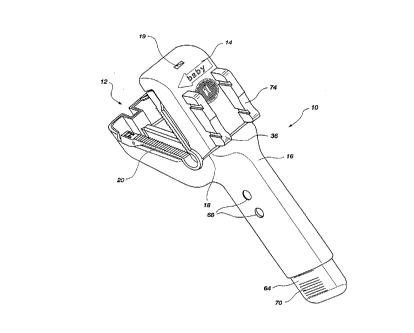
Figure l is a perspective view of an umbilical cord
clamping, cutting, and blood sampling device within the scope
of the present invention.
Figure 2 is an exploded perspective view of the device
shown in Figure l.
Figure 3 is a top view of interior of the handle portion
of the device shown in Figure l.
Figure 4 is a cross-sectional side view of an umbilical
cord clamping, cutting, and blood sampling device showing a
CA 0222l284 l997-ll-l7
WO !~6/36281 PCT/U~ 5/Q3315
placenta clamp, blood collection chamber, and a fluid
passageway between the blood collection chamber and a blood
container.
Figure 5 is a cross-sectional side view of the device
shown in Figure 4 showing the sliding action of a blade
assembly according to the present invention.
Figure 6 is a perspective view of an umbilical cord
clamp capable of use in the device of the present invention.
Figure 7 is a perspective view of one possible lid
interior configuration.
Figure 8 is a side, cross-sectional view of the lid and
handle illustrating one possible configuration of the
placenta clamp and blade assembly safety locks.
Figure 9 is a side view blade assembly showing a clamp
hook for retaining the umilical cord clamp.
Detailed DescriPtion of the Preferred Embodiments
Reference is now made to the figures wherein like parts
are referred to by like numerals throughout. With particular
reference to Figure 1, an apparatus for clamping, cutting,
and collecting a blood sample from an umbilical cord
according to the present invention is generally designated at
10. The component parts of apparatus 10 are shown in an
exploded perspective view in Figure 2. The apparatus 10
includes a housing 12 for receiving and entrapping a section
of umbilical cord (not shown). The housing 12 is formed by a
lid 14 and a handle 16 connected at a hinge 18 such that the
lid 14 may be moved from an open position to a closed posi-
tion. The open position allows an umbilical cord to be
inserted between the lid 14 and handle 16. A latch 19
located on the front of the lid 14 locks the lid shut when it
is closed. The lid 14 and handle 16 are preferably molded of
polymeric materials which permit easy snap-fit assembly. A
currently preferred polymeric material used to mold the lid
14 and handle 16 is ABS plastic.
The action of closing the lid 14 upon an umbilical cord
causes the cord to be clamped with a cord clamp 20. The
- 4 -
CA 0222l284 l997-ll-l7
WO 96/36281 PCT~S96/0334S
umbilical cord clamp 20 is preferably removably connected to
the housing 12. A large number of umbilical cord clamps are
known in the art, any number of which could be adapted for
use in the present invention. In a currently preferred
embodiment, the clamp 20 is a one-piece living hinge design
contA;ning a self-aligning latch. Clamp 20 is preferably
molded of a polymeric material having sufficient strength and
elasticity to provide the living hinge functionality.
Isoplast is a currently preferred polymeric material suitable
for molding the clamp 20.
A currently preferred clamp design is shown in Figure 6,
the umbilical cord clamp 20 is molded at a 65~ to 70~ angle.
The clamp 20 includes a living hinge 22 to keep the hinge
open until it is forcibly closed. Because the hinge 18 of
lid 14 and handle 16 can only open to about 55~, the clamp 20
produces a constant retention force against the lid 14 and
handle 16. The male latch member 24 includes a ratchet
surface 26 designed to engage female latch member 28. The
ratchet surface 2 6 provides the clamp 20 with several locking
positions. The ratchet surface 26 permits the cord clamp 20
to be used with umbilical cords that are either thin or
thick. In addition, the cord clamp 20 is designed to be
easily and securely closed with a i n; um of effort by the
medical practitioner. Once the latch members 24 and 28 have
engaged each other, the clamp 20 cannot be unlatched.
Removal of the clamp 20 from the umbilical cord requires
cutting of the living hinge 22. As shown in Figure 6, the
clamp 20 includes a rough or irregularly shaped clamping
surface 32 to firmly hold the umbilical cord within the
clamp.
Referring again to Figures 1 and 2, the housing 12
contains a blade assembly 36 for cutting the umbilical cord.
Attached to the blade assembly 3 6 is a sharp blade 38, such
0 as a standard stainless steel razor blade, for cutting the
umbilical cord. The sharp blade 38 includes a blade surface
40. In a presently preferred embodiment, the blade assembly
36 is slidably located in the lid 14 and configured to slide
-- 5
~ _ ,
CA 0222l284 Isg7-ll-l7
W096/36281 PCT~S96/03345
at an angle less than 90~, and preferably about 60~, with
respect to the blade surface 40 to provide a slicing motion
to cut the umbilical cord. Figure 5 shows a cross-sectional
view of the blade surface 40A prior to cutting the umbilical
cord and the blade surface 40B, shown in phantom lines, in
its position after cutting the umbilical cord. The top of
the blade assembly 36 is preferably textured to prevent the
thumb from slipping during actuation.
An interlock system is preferably provided in the
housing 14 to prevent the blade assembly 36 from engaging
until the lid 14 is closed. In embodiment illustrated in
Figures 7 and 8, a blade safety lock 41 prevents the blade
assembly 36 from engaging when the lid 14 is open. As shown
in Figure 8, the handle 16 preferably includes an angled ramp
surface 42 which causes the safety lock 41 to deflect when
the lid 14 is closed. With the safety lock 41 deflected, the
blade assembly 36 is free to be pressed downward to cut the
umbilical cord and to release the cord clamp.
An anvil 43 provides a surface for the blade 38 to cut
against. The blade surface 40 is buried in the anvil 43 at
the end of the cutting stroke. A wide variety of materials
can be used for the anvil 43, including synthetic polymeric
materials. Silicone rubber is a currently preferred anvil
material.
The blade assembly 36 preferably includes means for
releasing the clamp 20 from the housing 12 when the umbilical
cord is cut. In the illustrated embodiment, the clamp 20 is
released from the housing 12 by a cam 44 located on the side
of the blade assembly 36. When the blade assembly 36 is
actuated, the cam pushes the cord clamp 20 out of the housing
12.
The blade assembly 36 preferably includes a cord clamp
retainer. Because the cord clamp 20 is closed when the 14
lid is closed, it is desirable to keep the cord clamp affixed ?
to the housing 12 until the cord clamp 20 has been closed
around the umbilical cord and released from the housing when
the umbilical cord is cut. The embodiment illustrated in
-- 6 --
CA 0222l284 Isg7-ll-l7
WO96/36281 PCT~S96/03345
Figure g shows a clamp hook 46 for holding the cord clamp 20
to the housing 12. When the blade assembly 36 is actuated,
the cam pushes the cord clamp 20 out of the housing 12 and at
the same time the CA i ng action releases the cord clamp from
hook 46.
The handle 16 forms a blood collection ~h~ h~r 48. When
the umbilical cord is cut, blood drains into the blood
collection chamber 48. At the bottom of the blood collection
chamber 48 is a fluid passageway to a pair of standard vacuum
tubes 50 used in the medical industry for collecting blood
samples. The fluid passageway shown in Figures 2 and 4
includes a valve tee 52, an elbow 54, a pair of vacuum tube
needles 56 each with a rubber needle cover 58.
The elbow 54 is connected to the valve tee 52 to provide
a fluid passageway to a second vacuum tube. The elbow 54 is
preferably designed with a standard female lure lock taper
for a press fit onto the valve tee 52. The elbow is
preferably constructed of a polymeric material such as ABS
plastic. A pair of standard vacuum tube needles 56 are
attached to the valve tee 52 and to the elbow 54. The needle
covers 58 are commercially available. The needle covers
provide additional safety protection from inadvertent needle
sticks and prevent blood from draining out of the needles.
The valve tee 52 is preferably designed with a standard
male luer lock taper for easy press fit assembly into the
handle 16. A molded notch 60 at the base of the valve tee 52
permits the valve tee 52 to be broken (described in greater
detail below), thereby opening the fluid passageway between
the blood collection chamber 48 and the vacuum tubes 50. The
valve tee 52 is preferably constructed of a polymeric
material such as polystyrene.
The vacuum tubes are preferably housed within a sheath
64. A button 66 located on the side of the sheath 64 locks
into one of two holes 68 in the handle 16. The button 66 and
holes 68 provide a means of keeping the vacuum tubes 50 off
the needles 56 during manufacture and shipping and on the
needles 56 during use. The button 66 and holes 68 also
-- 7
CA 02221284 1997-11-17
WO 96136281 PCT/U~5/~3345
permit the user to readily determine the location of the
sheath 64 within the handle 12 and whether the vacuum tubes
50 have penetrated the vacuum tube needles 56. Raised ribs
70 located at the bottom of the sheath 64 allow the sheath to
5be easily removed from the handle 16. A pair of living hinge
flaps 72 located at the top of the sheath 64 retains the t
vacuum tubes 50 within the sheath 64. The flaps 72 are
configured to bend over the top of the vacuum tubes 50 to
facilitate removal of the vacuum tubes from the vacuum tube
10needles 56. Once the sheath 64 is removed from the handle
16, the flaps 72 can be easily bent out of the way to allow
removal of the vacuum tubes 50. The sheath is preferably
molded out of a polymeric material, such as polypropylene.
An absorbent gasket (not shown) preferably surrounds the
15blood collection ch~ hPr 48 in the handle 16 for collecting
and retaining excess blood that may exceed the capacity of
the collection chamber 48. The gasket also collects any
blood that may remain in the chamber after the collecting
process. Suitable gasket material is commercially available
20 in the medical industry. One currently preferred absorbent
gasket material is bonded cellulose acetate.
The apparatus 10 preferably includes a placenta clamp 74
located in the housing having a clamp surface 76 for gripping
or clamping the placenta side of the umbilical cord after it
25has been cut. The placenta clamp 74 facilitates delivery of
the placenta. In the illustrated embodiment, the placenta
clamp 74 is located in a slot within the lid 14. The
placenta clamp 74 preferably includes ratchet teeth 78 to
maintain clamping action of the placenta clamp against the
30umbilical cord. The ratchet teeth 78 engage a slot ratchet
80 in the lid. Just like the blade assembly 36, the placenta
clamp 74 is preferably configured to slide at an angle less
than 90~ with respect to the clamp surface 76. A valve break
off arm 82 extends downward from the side of the placenta
clamp 74 to break the valve tee 52 when the placenta clamp 74
is engaged.
CA 0222l284 lss7-ll-l7
WO96/36281 PCT~S96103345
An umbilical cord restraint 84 is preferably provided to
assist the placenta clamp in gripping and retaining the
umbilical cord. In the illustrated embodiment, the cord
restraint 84, located on the underside of lid 14, includes a
5 I plurality of needle-like or teeth-like projections which are
sharp enough to penetrate the umbilical cord when the lid 14
is closed.
An interlock system is optionally provided in the
housing 14 to prevent the placenta clamp 74 from engaging
until the lid 14 is closed. In embodiment illustrated in
Figures 7 and 8, a placenta clamp safety lock 86 prevents the
placenta clamp 74 from engaging when the lid 14 is open. As
shown in Figure 8, the handle 16 preferably includes an
angled ramp surface 88 which causes the safety lock 86 to
deflect when the lid 14 is closed. With the safety lock 86
deflected, the placenta clamp 74 is free to be pressed
downward to retain the umbilical cord and to facilitate
delivery of the placenta.
The present invention may optionally be constructed of
materials which permit the apparatus to be disposable.
Current technology permits one skilled in the art to
construct the apparatus entirely from non-metallic parts.
For instance, the sharp blade 38 and cord restraint 84 can be
manufactured from commercially available glass filled
material. Similarly, plastic vacuum tubes and vacuum tube
needles are commercially available. With the entire
apparatus manu~actured from non-metallic parts, the apparatus
can be easily incinerated leaving no metallic residue.
The apparatus of the present invention is prepared for
use by pressing the sheath 64 containing the vacuum tubes 50
further into the handle 16 such that the vacuum tube needles
58 penetrate the vacuum tubes 50. An umbilical cord is then
placed within the housing, and the lid 14 is closed upon the
, handle 16. The closing action of the lid causes the two
= 35 latch members 24 and 28 of clamp 20 to engage thereby
clamping the umbilical cord. The user then presses the blade
assembly 36 such that it slices the umbilical cord and
g
CA 0222l284 l997-ll-l7
WO96/36281 PCT~S96/0334S
releases the clamp 20 from the apparatus. Blood from the
freshly cut umbilical cord quickly fills the blood collection
chamber 48. The user then presses the placenta clamp 74
which breaks the valve tee 52 releasing the vacuum from the
vacuum tubes and creating a fluid passageway between the
blood collection chamber 48 and the vacuum tubes 50. The
vacuum tubes 50 quickly fill with blood from the umbilical
cord. Because the placenta clamp 74 and the cord restraint
84 provide a firm grip of the umbilical cord, delivery of the
placenta is facilitated.
From the foregoing, the present invention provides a
device and method of clamping and cutting the umbilical cord
and for obtaining an uncontaminated cord blood sample.
It should be appreciated that the apparatus and methods
of the present invention are capable of being incorporated in
the form of a variety of embodiments, only a few of which
have been illustrated and described above. The invention may
be embodied in other forms without departing from its
essential characteristics. The described embodiments are to
be considered in all respects only as illustrative and not
restrictive and the scope of the invention is, therefore,
indicated by the appended claims rather than by the foregoing
description.
-- 10 --