Note: Descriptions are shown in the official language in which they were submitted.
CA 02221434 1997-11-18 PATENT
.
P-3925
SYR~NGE FILL~NG AND DELIVERY DEVICE
5Field of the Invention
The subject invention relates to a device mountable on a hypodermic syringe or other
fluid delivery device which enables access to medication or other injectable liquid in vials
having elastomeric closures and the subsequent delivery of the medication or injectable liquid.
Back~round
A typical hypodermic syringe includes a syringe barrel with a mounting collar for
threadedly eng~ging the hub of a needle assembly. The needle assembly includes a hub and a
15needle cannula which are connected. In cases where the needle assembly is ~"~;"~ined
separately from the syringe until shortly prior to use, the medical practitioner selects an
applop.iate needle assembly for the procedure being carried out. The needle assembly is
removed from its sterile package, and the hub of the needle assembly is threadedly engaged
with the mounting collar of the syringe barrel.
20Liquid pharm~ceuticals and other injectable liquids are often stored in rigid containers
which can be accessed using a hypodermic syringe. Some containers for liquid
pharmaceuticals are glass vials with an elastomeric closure that can be penetrated by the needle
of a hypodermic syringe. To access the liquid in a vial, the plunger of the hypodermic syringe
is moved in a proximal direction to draw into the syringe barrel a volume of air substantially
25equal to the volume of medication that is desired. The sharp distal end of the needle is then
urged through the elastomeric closure of the vial, and the air in the syringe barrel is injected
into the vial. The distal end of the needle and the vial engaged therewith are then pointed
EXPRESS MAIL LABEL NO. EM368491442US (1)
P-3925 - CA 02221434 1997-11-18 "~-~
gravitationally upwardly. The practitioner ensures that the distal tip of the needle is covered by
the medication in the vial by manipulating the needle and the vial with respect to each other.
The plunger of the hypodermic syringe is then moved proximally to draw the desired volume of
medication through the needle and into the chamber of the syringe barrel
After withdrawing a desired volume of medication from a vial, the medical practitioner
may inject the medication into either a patient, another vial or an injection site of an
intravenous set or catheter. There is a trend toward needleless I.V. systems which do not
require a pointed needle cannula to pierce the injection site of an I.V. set. There are systems
that have injection sites covered by a pre-slit septum which can be accessed by a blunt cannula.
10 Accordingly, after withdrawing medication from a vial using a sharp needle the user must
remove the needle and install a blunt cannula if the medication will be used with an I.V. set
having a pre-slit septum. The user must take care to avoid accidental needle stick using a
needle to draw medication into a syringe and in the act of removing the needle to replace it
with a blunt c~nn~ Also, there is the potential of cont~min~ting the components when they
15 are installed and removed during the filling and delivery process.
Also, at the time of prefilling the syringe it may not be known whether medication will
be injected through an injection site having a pre-slit septum, which requires a blunt ç~nnlll~ or
through an injection site having a pierceable elastomeric septum which requires a needle
assembly having a cannula sharp enough to pierce the septum. In this latter case the
20 practitioner may use the hypodermic needle assembly which was used to fill the syringe.
Accordingly, there is a need for a device which will allow filling of a syringe from a vial
having a pierceable stopper and the subsequent delivery of the medication to an I.V. set
through a blunt cannula without having to handle or reshield sharp needles. There is also a
needle for a single device which can be used for withdrawing medication from a vial having a
25 pierceable stopper and for injecting this medication through an injection site having a
pierceable septum or a pre-slit septum without the need of ch~nging components during the
procedure.
P-3925 CA 02221434 1997-11-18
Summarv of the Invention
The subject invention relates to a fluid transfer device comprising an access cannula
assembly including an access cannula having a proximal end, a distal end, and a lumen
therethrough. A cutting edge at the distal end of the access cannula is provided for piercing a
vial stopper or a pierceable septum of an injection site. A hub has an open proximal end and a
distal end joined to the proximal end of the access cannula so that the lumen is in fluid
communication with the open proximal end of the hub. A blunt cannula assembly includes a
10 blunt cannula having a proximal end, a blunt distal end, and a passageway therethrough, and a
housing having an open proximal end and a distal end joined to the proximal end of the blunt
cannula. A portion of the access cannula is positioned within the passageway of the blunt
c~nn~ A spring is provided for helping to position the access cannula within the passageway
of the blunt cannula wherein a proxhl,ally directed force applied to the blunt cannula will cause
15 the spring to deflect and the cutting edge of the access cannula to project distally outwardly
past the distal end of the blunt cannula. Sealing structure is provided for sealing the access
cannula assembly and the blunt cannula assembly so that pressurized liquid passing through the
access cannula will exit the fluid transfer device through the distal end of the blunt c~nm-l~
A method for ~ re~ing an injectable liquid comprising the steps of:
(a) providing a syringe including a syringe barrel having an elongate cylindrical
body defining a chamber for ret~ining fluid, an open proximal end, a distal end and a tip
ext~n~ling from said distal end having a tip passageway therethrough in fluid communication
with the chamber, a stopper in fluid-tight slidable engagement inside the barrel and an elongate
plunger rod extending proximally from the stopper through the open proxil,.al end of the
25 barrel;
(b) providing a fluid transfer device comprising an access cannula assembly
including an access cannula having a proximal end, a distal end, and a lumen therethrough, a
P-3925 -- CA 02221434 1997-11-18,
cutting edge at the distal end of the access cannula for piercing a vial stopper, a hub having an
open proximal end and a distal end joined to the proximal end of the access cannula so that the
lumen is in fluid communication with the open proximal end of the hub; a blunt cannula
assembly including a blunt cannula having a proximal end, a blunt distal end, and a passageway
5 therethrough, a housing having an open proximal end and a distal end joined to the proximal
end of the blunt cannula; spring means for helping to position the access cannula within the
passageway of the blunt cannula wherein a proximally directed axial force applied to the blunt
cannula will cause the spring to deflect and the cutting edge of the access cannula to project
distally outwardly past the distal end of the blunt cannula; and means for sealing the access
10 cannula assembly and the blunt cannula assembly so that pressurized liquid passing distally
through the access cannula will exit the fluid transfer device through the distal end of the blunt
cannula;
(c) connecting the syringe filling device to the syringe so that the tip is positioned
within the open pro~il.lal end of the hub, and the chamber is in fluid communication with the
15 lumen of the access c~nn~
(d) providing a vial having a pierceable stopper and co-"~ g an injectable liquid;
(e) placing the blunt distal end of the blunt cannula in contact with the pierceable
stopper,
(f) moving the syringe barrel toward the septum causing the spring to deflect and
20 move the blunt cannula assembly proximally and causing the cutting edge on the distal end of
the access cannula to pierce the pierceable stopper to establish fluid communication between
the interior of the vial and the chamber of the syringe;
(g) withdrawing the desired amount of injectable liquid from the vial into the
chamber by moving the plunger rod in a proximal direction with respect to the barrel; and
(h) withdrawing the access cannula from the stopper of the vial.
p_3925 , CA 02221434 1997-11-18
Brief Description of the Orawin~Js
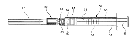
Fig. I is a side-elevational view of the fluid transfer device of the present invention
attached to a syringe.
Fig. 2 is an exploded view of the fluid transfer device of the present invention and a
syringe barrel.
Fig. 3 is an enlarged side-elevation view of the fluid transfer device.
Fig. 4 is a cross-sectional view of the fluid transfer device of Fig. 3 taken along line
4-4.
Fig. 5 iS a cross-sectional view of the fluid transfer device of Fig. 3 taken along line
5-5.
Fig. 6 is a fluid transfer device of Fig. 5 further illustrating the cutting edge of the
access cannula protruding from the distal end of the blunt cannula.
Fig. 7 is a side-elevational view of the fluid transfer device and syringe being used to
15 draw liquid from a stoppered vial.
Fig. 8 is a side-elevational view illustrating the fluid ll~n~rer device and syringe being
used to inject liquid into an injection site of an I.V. set.
Detailed Description
While this invention is satisfied by embodiments in many di~rele.,l forms, there are
shown in the drawings and will be herein described in detail a pl~relled embodiment of the
invention with the understanding that the present disclosure is to be considered exemplary of
the principals of the invention and not intended to limit the scope of the invention to the
25 embodiment illustrated. The scope of the invention will be measured by the appended claims
and their equivalents.
P-3925 . CA 0222l434 l997-ll-l8 ,'
Referring to Figs. 1-8, a fluid transfer device 20 of the present invention includes an
access cannula assembly 21 including an access cannula 22 having a proximal end 23, a distal
end 25, and a lumen therethrough. A cutting edge 28 iS provided at the distal end of the access
cannula for piercing a vial stopper or a pierceable septum of an ~.V. set injection site A hub
29 having an open proximal end 31 and a distal end 32 which is joined to the proximal end of
the access cannula so that the lumen of the access cannula is in fluid communication with the
open proximal end of the hub.
A blunt cannula assembly 33 includes a blunt cannula 34 having an open proximal end
35, a blunt distal end 37, and a passageway 38 therethrough. A housing includes an open
10 proximal end 41 and a distal end 43 joined to the proximal end ofthe blunt cannula. Although
the blunt cannula assembly can be made by joining a separate housing and blunt cannula in this
embodiment is preferably integrally formed of thermoplastic material having a one-piece
construction. The vial access cannula assembly and the blunt cannula assembly are positioned
in a concentric relationship wherein a portion of access cannula 22 iS within the passageway 38
15 of the blunt c~nn~
A spring 45 iS positioned between hub 29 and housing 40 for helping to position access
cannula 22 within passageway 38 of blunt cannula 34 wherein a proximally directed axial force
F, as illustrated in Fig. 6, applied to the blunt cannula will cause spring 45 to deflect and
cutting edge 28 of access cannula 22 to pro~ect distally outwardly past blunt distal end 37 of
20 the blunt c~nnul~ Spring 45 in this embodiment is preferably made of elastic material such as
natural rubber, synthetic rubber or thermoplastic elastomer. Spring 45 includes a longitudinal
conduit 46 which allows it to be slidably placed over access cannula 22 and trapped between
hub 29 and housing 40. The spring may also be a coil spring similarly placed or placed
elsewhere such as ?~ c.ent to the access cannula rather than around the access c~nnlll~ The
25 spring can also be constructed of cantilever elements projecting to or from the housing or the
hub so that the cantilever elements are deflected upon axial movement of the housing toward
P-3925 CA 02221434 1997-11-18
the hub. The spring element may also be placed around the periphery of the hub, for example,
between projections 30 on the hub and the proximal end ofthe housing.
The fluid transfer device of the present invention also preferably includes means for
sealing the access cannula assembly and the blunt cannula assembly so that pressurized liquid
5 passing distally through the access cannula will exit said fluid transfer device through the distal
end of the blunt c~nn~ The means for sealing helps assure that liquid intended for delivery
from the blunt distal end of the blunt cannula does not exit the fluid transfer device in other
areas. For example, moving through the space between the outside surface of the access
cannula and the passageway of the blunt cannula to escape through the space between the hub
10 and the housing. Means for sealing can be accomplished by making the access cannula large
enough to substantlally occlude the passageway of the blunt cannula to help prevent liquid
firom passing between the outside of the cannula and the inside of the passageway. Sealing
means can also be accomplished by placing a resilient sealing element such as an O-ring or
molded annular flange which can seal the space between the access cannula assembly and the
15 blunt cannula assembly. In this prerelled embodiment, spring 45 also functions as a sealing
means. In particular, spring 45 is an elastomeric cylindrically shaped element which fits around
cannula 22 and is slightly compressed when the fluid Ll~n~rer device is in its resting position so
that distal end 47 of the spring seals the periphery of cannula 22 and annular edge 44 in the
housing to resist the passage of liquid in a proximal direction from the space between the
20 outside of the access cannula and the passageway of the blunt cannula. The elastomeric
element can preferably seal the space between the cannula and the housing or between the hub
and the housing or both.
In this embodiment the access cannula assembly preferably includes access cannula 22
being formed of metal such as stainless steel and hub 29 being formed of a thermoplastic
25 material with the components being joined together by various means including epoxy
adhesive. The use of a metal cannula allows a small outside diameter while still m~int~ining
considerable strength. Also, the dimensions and tolerances of the outside diameter of the metal
P-3925 CA 02221434 1997-11-18
cannula can be closely held for slidable engagement within passageway 38 of the blunt cannula
to help function as sealing means as described hereinabove. Also, the high strength and
reduced diameter of a metal cannula helps reduce penetration forces as the cannula enters a
vial stopper or pierceable septum. It is also within the purview of the instant invention to have
5 an access cannula assembly wherein the cannula and the hub are integrally formed of a single
material such as thermoplastic.
The fluid transfer device of the present invention is suitable for use with fluid delivery
devices such as syringes. For the purpose of illustration, fluid transfer device 20 iS connected
to a syringe 50 comprising a syringe barrel 51 having a distal end 52, an open proximal end 53
10 and a circular side wall 55 defining a chamber 57 for retaining fluid Volume measuring indicia
58 are on the barrel for measuring the volume of liquid to be delivered. The distal end of the
syringe barrel is connected to hub 29 SO that the lumen of access cannula 22 iS in fluid
communication with chamber 57 of the syringe barrel. In this embodiment, distal end 52 of the
syringe barrel includes a frusto-conically shaped tip 59 which engages at frusto-conically
15 shaped surface 26 in open proximal end 3 I of the hub. The distal end of the syringe barrel also
p~re~bly, but not necessarily, includes a locking luer-type collar 62 concentrically
surrounding tip 59. The luer collar has an internal thread 63 which engages radial projections
30 on hub 29 to hold the hub securely to the barrel. It is within the scope of the present
invention to include various hub configurations to attach to a variety of other medical fluid
20 handling devices. The hub configuration described hereinabove, having a frusto-conically
shaped interior cavity, reflects one of these many possibilities. Many syringes and fluid
h,.ndlin~ devices, such as stopcocks and adapters, and other fluid h~n(lling devices contain luer
slip and locking luer-type fittings to which a hub having a frusto-conically shaped interior
cavity will properly engage. It is within the purview of the present invention to provide a fluid
25 transfer device wherein the hub of the access cannula assembly is integrally molded with the
syringe barrel.
P-3925 CA 02221434 1997-11-18
A stopper 64 iS positioned in chamber 57 in sliding fluid-tight engagement with circular
side wall 55. A rigid elongate plunger rod 65 is connected to the stopper and extends
proximally through the open proximal end of barrel 51. The stopper and the plunger rod can
be made of one-piece unitary construction. Force applied to the plunger rod causing sliding
5 movement of the stopper in a proximal direction draws fluid through conduit 61 into chamber
57. Conversely, sliding movement of stopper 64 in a distal direction urges fluid from chamber
57 through conduit 61.
Fluid transfer device 20 preferably, but not necessary, includes a removable shield 67
having an open proximal end 68, a distal end 69 and a side wall 70 therebetween defining a
10 recess 71 in the shield. The shield is removably connected to the fluid transfer device so that
blunt cannula 34 is contained within recess 71 of the shield. The shield helps protect the blunt
cannula from contamination before use. In this embodiment the shield preferably frictionally
engages housing 40 of the blunt cannula assembly. However, it is within the purview of the
present invention to provide a shield which engages the hub of the access c~nn~
When connecting fluid transfer device 20 to a syringe such as syringe 50 having a
locking luer-type collar the fluid l~all~rel device is rotated to advance projections 30 on hub 29
along internal thread 63 of collar 62. The rotation will pull the hub toward the syringe barrel
tightly eng~ging tip 59 of the syringe barrel into the open proximal end of hub 29. Because of
the torque required to engage the fluid transfer device and a syringe barrel having a locking
luer-type collar it is desirable to have torque transmining means for allowing rotational force
applied to the housing of the blunt cannula to be 1, ~n~-l~iUed to the hub of the access cannula
assembly so that the user has a larger surface to manually apply rotational forces to the fluid
transfer device and such forces are effectively transmitted to the hub. In this embodiment
torque ~,~nsnlllLing means includes one or more protuberances on the hub such as axial ribs 39
which engage a slot in housing 40 formed by axial projections 24 as best illustrated in Fig. 4.
Any combination of protuberances and/or recesses on the hub or housing which are capable of
P-3925 CA 02221434 1997-11-18
tr~n~mit~ing sufficient torque to engage the hub to the syringe barrel are s~ti~f~ctory for
functioning as torque transmitting means.
It is also plerelled to have structure for connecting the hub and the housing to prevent
the blunt cannula assembly from being separated from the access cannula assembly and with
5 certain spring configurations, to keep the spring under a slight colllplessive force, especially
when the spring is also being used as sealing means. In this embodiment, bamer wall 36 at the
distal end of hub 29 engages longitudinal ribs 24 to help prevent separation of the blunt
cannula assembly and the access cannula assembly. These components must be configured to
allow the longitudinal ribs to snap over the barrier wall during assembly of the fluid transfer
I 0 device.
Fluid transfer device 20 of the present invention, coupled with a fluid delivery device,
such as syringe 50 can be used to access fluid in a vial having a pierceable stopper and deliver
the fluid to an injection site on an I.V. set or catheter regardless of whether the injection site
has a pre-slit septum or a pierceable septum. This is a major advantage of the present
15 invention. No longer are multiple devices needed to fill a syringe from a stoppered vial and
deliver the liquid or other medication through an I.V. injection site having a pre-slit septum.
The instant invention contains a blunt cannula and an access cannula having a cutting edge at
its distal end which is sharp enough to pierce rubber stoppers and septums but does not have to
be and is preferably not sharp enough for injection through the skin. Accordingly, there will be
20 less chance to pierce the skin with a dull cutting edge suitable for vial stopper piercing but not
for skin injection.
As best illustrated in Fig. 7 the fluid ll~n~r~l device can be used with syringe 50 to
access injectable liquid or medication, such as fluid 73, contained within vial 74 having a
pierceable stopper 75. The fluid is accessed by placing the blunt distal end of the blunt cannula
on top surface 76 of stopper 75 and applying an axial force through the syringe barrel in
direction A. Because the blunt cannula cannot pierce the vial stopper, the top surface of the
vial stopper responding with an equal and opposite force to force A, will push the blunt
P-3925 ~ CA 02221434 1997-ll-18
cannula assembly axially proximally toward hub 29 causing the spring to compress and cutting
edge 28 of the access cannula to protrude outwardly from the distal end of the blunt cannula
and pierce the stopper 75. When force A is discontinued the cutting edge will, by action of the
spring, retract back into the passageway of the blunt cannula. At this point, liquid can be
drawn into the syringe barrel using known methods such as the method described hereinabove.
The fluid transfer device is then withdrawn from the stopper of the vial.
The filled syringe 50 with fluid access device 20 attached is now transferred to the
point of use where it can be used to inject fluid into a patient through an I.V. set or a catheter
having an injection site with a pre-slit or pierceable septum. Specifically, as illustrated in Fig.
0 8, an I V. set 80 can include a a housing 81 having a hollow interior conduit 82 and a flexible
tube 83 connected to the vascular system of a patient, usually through a catheter. Housing 81
also includes another flexible tube 85 which is connected to a source of I.V. fluid. Housing 81
also includes port 86 having a conduit 87 therethrough in communication with the interior
conduit 82. A pre-slit septum 88 covers the open end of conduit 87. The most common ports
15 are covered by pierceable septums or pre-slit septums and are known in the art and sometimes
referred to as "PRN" from the Latin E~ L nata meaning "as the need arises". Septum 88 is a
pre-slit septum having a slit 89 therein. Septum 88 effectively seals conduit 87 from the
exterior of the housing. However, access to the conduit can be achieved by pressing blunt
distal end 37 of blunt cannula 34 against the area of the septum cont~ining slit 89. General
20 force applied to the syringe in an axial direction will cause the blunt end of the cannula to enter
the conduit through the slit which is forced open by the blunt c~nnul~ Preferably, the force
required to open the slit is less than the force required to compress the spring and allow the
cutting edge of the access cannula to protrude from the distal end of the blunt c~nn~ The
liquid may now be injected into the I.V. set. Upon completion and removal of the blunt
25 cannula from the conduit, the slit portion of the septum automatically reseals itsel~ If the
septum on the port of the I.V. set is not pre-slit. The fluid access device of the present
invention can be used in the same manner as it is used with a pre-slit septum. However, the
P-3925 CA 02221434 1997-11-lY
greater force required to penetrate a pierceable, non-pre-slit septum will cause the spring to
compress and the cutting edge of the access cannula to protrude beyond the distal end of the
- blunt cannula to pierce the septum in a similar manner as when the fluid transfer device is used
to pierce the pierceable stopper of the medication vial. The fluid access device of the present
S invention effectively seals itself so that fluid may be injected through the access cannula or
through the blunt cannula, and the cutting edge of the access cannula may be exposed solely by
axial proximally directed force exerted on the distal end of the blunt c~nn~ When the axial
force is discontinued the blunt cannula assembly will return to a position wherein the cutting
edge of the access cannula is contained within the passageway of the blunt c~nnlll~ All
10 relative motions are generally axial and prompted by forces ~ snl;lled through the distal end
of the blunt cannula.
~ 12