Note: Descriptions are shown in the official language in which they were submitted.
CA 02221806 1997-11-21
W 096/3794S PCTfUS96106237
ONE-PIECE ~r-~T RETURN PATH ASSEMBLY
FOR A DISK DRIVE ACTUATOR
RP~CR~ROllND
Field of the Invention
The present invention relates to data storage
devices, or disk drives, for storing digital information, and
more particularly, to a one-piece magnet return path assembly
for a voice coil motor in a disk drive.
Description of the Prior Art
Disk drives o~ten employ voice coil actuators for
positioning the read/write heads of the disk drive over the
surfaces of a disk-shaped storage media. Magnetic flux for
the voice-coil motor is typically generated by a magnetic
circuit comprising a return path assembly and a pair of
15 magnets. The return path assembly is usually comprised of a
top plate, a bottom plate, and a plurality of standoffs. The
standoffs hold the top and bottom plates apart at a
predetermined distance to form an air gap ~or receiving a
coil coupled to one end of the actuator. Magnets are
typically bonded to the inner walls of both the top and
bottom plates. The top and bottom plates, along with the
standoffs, form a flux return path for a magnetic field
generated by the top and bottom magnets. The magnetic ~lux
within the air gap between the magnets induces torque on the
25 actuator in response to an electric current in the actuator
coil.
In prior art disk drives o~ the type described
above, the top and bottom plates and the standoffs are formed
CA 02221806 1997-11-21
W 096/37945 PCT~US96/06237
separately from a magnetically permeable material, such as a
low carbon steel. These separate components are then
assembled together using suitable hardware. U.S. Patent No.
5,313,124 discloses such a prior art return path assembly.
Unfortunately, these prlor art return path
assemblies increase the assembly time and manufacturing costs
of a disk drive, since the various components must be
purchased separately, along with suitable hardwarel and then
assembled together in the disk drive. There is a need,
therefore, for a more cost-effective magnet return path
assembly for a disk drive that overcomes the disadvantages of
prior art assemblies. The present invention satisfies this
need.
SUMMARY OF THE lNV~NLlON
The present invention is directed to a one-piece
magnet return path assembly for a disk drive actuator. The
one-piece magnet return path assembly comprises an upper
plate, a lower plate and a plurality of standoffs extending
between the upper and lower plates and establishing a pre-
determined spacing between said upper and lower plates. The
upper and lower plates and the plurality of standoffs are
stamped integrally from a single sheet of magnetically
permeable material. The blank is then bent at predetermined
locations to form the completed one-piece magnet return path
assembly. Preferably, the magnetically permeable material
comprises a low carbon steel. The one-piece assembly of the
present invention reduces costs and assembly time in a disk
drive.
The foregoing and other objects, features and
advantages of the invention will become evident hereinafter.
BRIEF DESCRIPTION OF THE DRAWINGS
The foregoing summary, as well as the following
detailed description of the preferred embodiment, is better
understood when read in conjunction with the appended
35 drawings. For the purpose of illustrating the invention,
CA 02221806 1997-11-21
W O9~/37945 PCTrUS96/06237
there is shown in the drawings an embodiment that is
presently pre~erred, it being understood, however, that the
invention is not limited to the specific methods and
instrumentalities disclosed. In the drawings:
Figure 1 shows an exemplary disk drive in which the
one-piece magnet return path assembly of the present
invention may be employed;
Figure 2 shows a blank from which the one-piece
magnet return path assembly of the present invention may be
formed;
Figure 3 is a perspective view of the one-piece
magnet return path assembly of the present invention; and
Figure 4 is a top view of the one-piece magnet
return path assembly of the present invention.
DET~TT-~n DESCRIPTION OF THE PREFERRED EMBODIMENTS
Referring to the drawings wherein like numerals
indicate like elements throughout, there is shown in Figure 1
an exemplary disk drive 20 in which the present invention may
be employed. The exemplary disk drive 20 is of the type that
receives a removable disk cartridge, however, the present
invention is by no means limited thereto. For example, the
present invention can also be employed in a fixed-disk type
drive.
As shown in Figure 1, the exemplary disk drive 20
comprises a chassis 21 on which a number of disk drive
components are mounted. A ~ront panel 24 of the disk drive
20 has a substantially horizontal opening 22 for receiving a
removable disk cartridge (not shown). An eject button 26 is
provided on the front panel for ejecting a disk cartridge
from the disk drive 20. A spindle motor 110 is mounted on
the chassis 21 to provide a means for rotating the storage
media within a disk cartridge.
An actuator arm 32, which forms part of a radial
arm voice coil actuator, is pivotally mounted to the drive
cha.ssis 21 at 38. The actuator arm 32 has a plurality of
suspension arms 34 at its distal end that each carry a
CA 02221806 1997-11-21
W 096/37945 PCTrUS96106237
read/write head 36 for recording and reading information to
and from the storage media of a disk cartridge (not shown).
A head loading mechanism 35 facilitates loading of the
magnetic heads onto the storage media. A voice coil element
(not shown) is affixed to the other end 42 of the actuator
arm 32 for controlling the rotational movement of the arm 32.
A magnet return path assembly 50 according to the present
invention is mounted to the chassis 21 and provides a magnet
return path for the voice coil actuator.
Figure 2 is a plan view of a blank 51 of a one-
piece magnet return path assembly in accordance with the
present invention. Preferably, the blank 51 is stamped from
a single sheet of magnetically permeable material. In the
present embodiment, the blank 51 is stamped from a single
sheet of low carbon steel (e.g. 1006 steel) having a
thickness of approximately 2.5 mm. A finish of zinc chromate
may be applied to the steel blank.
The blank comprises a first plate 52, which defines
a lower plate of the one-piece magnet return path assembly,
and a second plate 54, which defines an upper plate of the
return path assembly, as described hereinafter. A plurality
of standoffs 56, 58, 60 are formed integrally with the upper
and lower plates 52, 54 of the blank 51. In the present
embodiment, two of the standoffs 56, 58 extend between the
25 upper and lower plates 52, 54. Mounting holes 66 are formed
in the lower plate 52 of the blank 51 to facilitate mounting
of the completed assembly in a disk drive. The upper plate
has cutaway portions 62, 64 to facilitate access to the
mounting holes 66.
According to the present invention, the blank 50 is
bent in predetermined locations to form the completed one-
piece magnet return path assembly of the present invention.
More particularly, in the present embodiment, the blank 51 is
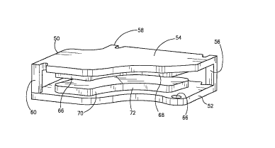
bent at locations "A", "B" and "C". Figure 3 illustrates the
35 resulting one-piece magnet return path assembly 50. As
shown, the blank 51 is bent at locations "A" and ~B~ such
that the upper and lower plates 52, 54 of the blank 51 are
CA 02221806 1997-11-21
W O 96/37945 ~CT~US96/06237
disposed in parallel planes, one above the other. The blank
51 is bent at location "C" to form the third standoff 60.
The standoffs 56, 58, 60 extend between the upper and lower
plates 52, 54 to establish a predetermined spacing between
A 5 the plates 52, 54. In the present embodiment, the spacing
between the upper and lower plates 52, 54 is approximately
8.0 mm. While three standoffs 56, 58, 60 are employed in the
present embodiment to maintain the plate-to-plate spacing, in
other embodiments, the number of standoffs can be increased
10 or decreased.
A progressive die can be used to make the necessary
bends in the blank 51. For example, the progressive die can
be used to bend the lower plate 52 of the blank at locations
"A" until the lower plate 52 extends substantially
15 perpendicular to the still planar standoffs 56, 58 and upper
plate 54. A second bending step can then serve to bend the
upper plate 54 upward at locations "B", until it extends
substantially parallel to the lower plate 52. A third
bending step can serve to bend the third standoff at location
20 "C" until it extends perpendicularly between the upper and
lower plates 52, 54. The various bending steps can be
performed in any suitable order.
A plurality of magnets 66, 68, 70, 72 are affixed
to the upper and lower plates in a conventional manner using,
25 for example, an adhesive. Figure 4 is a top view of the
completed one-piece assembly showing the relative placement
o~ the magnets 66, 70 and 68,72. In the present embodiment,
the magnets are approximately 2.5 mm thick, and the resulting
air gap between the magnets of the upper and lower plates 52,
30 54 is approximately 3.0 mm. The gap between the upper and
lower magnets receives the coil (not shown) of the disk drive
actuator 32 in a conventional manner. As best shown in
Figure 4, the cutaway portions 62, 64 of the upper plate 54
provide access to the mounting holes 66 of the lower plate 52
35 to ~acilitate mounting of the assembly 50 in a disk drive.
As the foregoing illustrates, the present invention
is directed to a one-piece magnet return path assembly for a
CA 02221806 1997-11-21
W 096/37945 PCTrUS96/06237
disk drive and to a method of making same. The one-piece
magnet return path assembly of the present invention reduces
costs and simplifies assembly of a disk drive. It is
understood that changes may be made to the embodiments
5 described above without departing from the broad inventive
concepts thereof. Accordingly, the present invention is not
limited to the particular embodiments disclosed, but is
intended to cover all modifications that are within the
spirit and scope of the invention as defined by the appended
claims.