Note: Descriptions are shown in the official language in which they were submitted.
CA 02221872 1997-12-09
WO 97/00717 PCT/US96/10549
FILTER AND METHOD FOR MMING A FILTER
Field of the Invention
The present invention relates to a filter and to a
~ method for making a filter. More particularly, the filter
is useful as a recirculation filter in a hard disk drive
enclosure.
Backgrou d of the invention
Hard disk drives are enclosures in which an inflexible
platter coated with magnetic material is spun very rapidly.
A magnetic read/write head "flies" only a few microns
above the disk on an air cushion. To provide a hard disk
drive having high efficiency, it is desirable to position
the head as close to the disk as possible without touching
it. -
It has been found that particulate and gaseous
contaminants act to reduce efficiency and longevity of hard
disk drives. Common sources of contaminants in disk drives
include leaks which may or may not be intentional, the
manufacturing environment which can contain certain
contaminants, and the materials incorporated into the disk
drive which give off particulates and gases. It is of
particular concern that organic vapors can be generated
inside disk drive enclosures during normal operating
conditions when, for example, the temperature exceeds
150 F. Such temperatures can be achieved by simply leaving
the computer in the trunk of a car on a hot day.
Recirculation filters have been used in hard disk
drives for removing contaminates. Such filters have been
effective for removing particulate contaminants. They are
not, however, suitable for removing organic vapors since
they do not have a capacity for permanently adsorbing
organic vapors. To provide enhanced organic vapor removal,
CA 02221872 1997-12-09
WO 97/00717 PCT/US96/10549
2
it has been proposed to include activated carbon in
recirculation filters. Activated carbon in the form of
granules or fiber can adsorb organic vapors. However,
permeability of filters including such activated carbon is
sacrificed. This results in an overall lower effectiveness
of the filter.
Another problem is that activated carbon granules or
fibers can escape filtering media and contaminate the hard
disk drive enclosure. Previous attempts at controlling
carbon migration include coating the edges of filters with
resins or epoxies, and using additional material and/or
mechanical clamps to seal the filter edges. Although these
attempts help control carbon migration, it would be
desirable to further reduce carbon migration.
Svinmary of the Invention
A filter is provided by the present invention. The
filter includes a layer of particulate adsorbing medium and
a layer of organic vapor adsorbing medium. Preferably, the
filter has a figure of merit greater than about 10 and a
capacity for permanently adsorbing organic vapors. The
figure of inerit is calculated based upon a fractional
efficiency determined for particles having a size of 0.3 m
in an air flow having a velocity of 10.5 ft./min. and for
Frazier permeability at 0.5 inches H20.
The filter can include an organic vapor adsorbing
layer comprising porous adsorbent beads, a first
particulate removal layer on one side of the organic vapor
adsorbing layer, and a second particulate removal layer on
the second side of the organic vapor adsorbing layer. The
porous adsorbent beads can be activated carbon beads which
allow air to pass therethrough with little resistance and
which have pores providing increased surface area for
CA 02221872 1997-12-09
WO 97/00717 PCT/US96/10549
3
adsorbing organic vapors. The particulate removal layers
can be made of electrostatic media and/or
polytetrafluoroethylene.
A method for preparing a filter for use in removing
particulates and organic vapors from an air stream is
provided by the present invention. The method includes the
step of providing filter materials which will provide a
figure of merit of greater than about 10 and an organic
vapor adsorbing capacity. The porous beads can be capable
of adsorbing trimethylpentane and hydrogen sulfide.
A method for impregnating porous beads with an
impregnant for adsorbing acid gases is provided by the
present invention. The process includes the steps of
dissolving impregnant in a solvent to provide a solution of
impregnant and solvent, immersing porous beads in the
solution to allow solution to coat the porous beads, and
drying the coated porous beads to evaporate the solvent.
Preferably, the solvent is distilled water, and the
impregnant is selected from the group consisting of calcium
carbonate, potassium carbonate, sodium carbonate, and
mixtures thereof.
Brief Description f tlie Draw3.n.cre
FIGURE 1 is a schematic view of a portion of a hard
disk drive containing a filter according to the present
invention;
FIGURE 2 is a partial cross-sectional view of the
filter shown in FIGURE 1;
= FIGURE 3 is a graph of disk drive chemical clean-up
comparison of recirculation filters from Example 4; and
FIGURE 4 is a graph of disk drive particulate clean-up
comparison of recirculation filters from Example 4.
CA 02221872 1997-12-09
WO 97/00717 PCT/US96/10549
4
Detailed Description of the Invention
The preferred embodiment of the invention is now
described in detail with reference to the drawings, wherein
like reference numerals represent like parts and assemblies
throughout the several views. Reference to the preferred
embodiment does not limit the scope of the invention, which
is limited only by the scope of the claims attached hereto.
Referring to FIGURES 1 and 2, a filter in accordance
with the present invention is depicted at reference numeral
10. The filter 10 is shown in use as a recirculation
filter inside the hard disk drive enclosure 12, and is
referred to as the "recirculation filter" or more
conveniently as the "filter." In the embodiment of the
invention shown, the filter is referred to as a type of
is "pillow filter" which is meant to describe filters having a
pillowy shape and which are sealed on the edges to
discourage the components of the filter from escaping. As
will be apparent from the following description, the filter
of the invention can have other structures or shapes, such
as, tubular, bag-like, etc.
It is a preferred embodiment of the present invention
that the filter can function as a recirculation filter in
hard disk drives. The filter is particularly advantageous
as a recirculation filter in hard disk drives because it
has a low pressure drop across the filter and a high degree
of filtering of particulate and gaseous contaminants from
the environment inside a disk drive. Of course, the filter
of the invention can be used in many other applications
where these properties are desired.
As the disk 14 rotates counterclockwise, a stream of
air and gases is caused to flow or circulate in the same
direction and is represented by the arrows. By strategic
CA 02221872 1997-12-09
WO 97/00717 PCTIUS96/10549
placement of the filter 10 across the air stream, one
skilled in the art can take advantage of the air flow to
provide a filtering effect during operation of the hard
disk drive 12 to remove contaminants and thereby provide
5 enhanced air clarification. It should be appreciated that
in the context of this invention the reference to the
"removal" of contaminants refers to the clarification of
the stream being filtered. In a preferred embodiment, it
is believed that the stream being clarified in a hard disk
drive enclosure is an air stream. It should be
appreciated, however, that streams of other gases or
liquids could also be clarified by the filter of the
present invention. The removal of contaminants from a
liquid or gas stream by a filter can also be referred to as
entrapment of the contaminants inside the filter.
The filter 10 is held in place in the disk drive
enclosure 12 by the supports or frame 15. The frame can be
provided around the filter and can be separable from the
enclosure. If desired, the filter can be welded to the
frame or "fitted" in place.
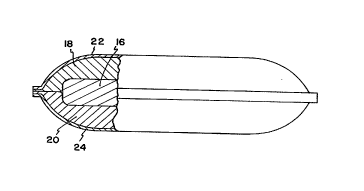
Now referring to FIGURE 2, a partial cross section of
the filter 10 is shown. The filter 10 includes an organic
vapor removal layer 16 and particulate removal layers 18,
20. The organic vapor removal layer 16 can provide
permanent removal of certain organic vapor contaminants,
and the particulate removal layers 18, 20 can provide
permanent removal of certain particulate contaminants. It
should be understood that "permanent removal" refers to the
removal or entrapment of contaminants which are not
released from the filter during normal operating conditions
for a particular application. In the case of the filter 10
which is used inside the hard disk drive enclosure 12, the
CA 02221872 1997-12-09
WO 97/00717 PCT/US96/10549
6
permanent removal of certain particulate and vaporous
contaminants from the environment inside the hard disk
drive enclosure 12 reflects the fact that those
contaminants are not released into the stream of air during =
normal operating conditions. During conditions which are
not normal, for example, when the temperature of the
organic vapor removal layer is heated in excess of normal
operating temperatures, it may be able to force organic
vapors out of the organic vapor removal layer.
It should be understood that the organic vapor removal
layer 16 can, if desired, provide some degree of
particulate contaminant removal. The particulate removal
layers 18, 20, however, generally do not provide for
permanent organic vapor removal. The reason for this is
that the materials which make up the particulate removal
layers 18, 20 do not physically function to achieve
permanent removal of organic vapor contaminants. Although,
organic vapors may attach to these layers, they can usually
become released during the normal operation of the hard
disk drive.
The scrim 22, 24 are provided to keep the components
of the filter 10 from escaping into the environment of the
hard disk drive enclosure 12. The scrim 22, 24 should have
a porosity which is sufficient to minimize pressure drop
but, at the same time, contain the components of the filter
10. if, for example, the particulate removal layers are
made of a fibr_ous non-woven material, the scrim should be
sufficient to discourage the fibers from escaping. The
scrim could be omitted from the filter if they are not
needed to prevent or discourage components of the filter
from escaping. It should also be appreciated that a filter
according to the present invention can be provided having
CA 02221872 1997-12-09
WO 97/00717 PCT/US96/10549
7
organic vapor and particulate contaminant removal
properties without a scrim.
Development of filtering medium and methods for the
= manufacture thereof according to the present invention are
based, in part, upon a number of observations made during
experimentation with other recirculation filters. In
particular, it was observed that a problem with many prior
art recirculation filters is that they either do not
provide sufficient removal of certain contaminants or that
they provide insufficient permeability which results in an
inability to sufficiently clean the environment. If the
permeability of a recirculation filter becomes too low, the
filter tends to act like a wall rather than a filter.
Since recirculation filters generally function passively by
virtue of their placement in a stream of moving air, a low
permeability will tend to encourage air to flow around
rather than through the filter. As a result, it will take
longer to purify the air.
Applicants discovered an important relationship
between the ability of a recirculation filter to provide
sufficient clarification of a stream and an calculable
property called Figure Of Merit (FOM). Accordingly, the
FOM of a filter or filter medium is calculated to evaluate
the usefulness of the filter or filter medium in a
recirculation filter. It should be appreciated that the
FOM can be used to evaluate the usefulness of a filter or
filter medium for other applications as well, including
open or closed recirculation systems, and room air
cleaners, automotive cabin air cleaner and the like. For
purposes of the description of the present invention, a
filter medium can be a whole filter or any part or layer of
a filter.
CA 02221872 1997-12-09
WO 97/00717 PCT/US96/10549
8
The Figure of Merit, discussed more fully hereinafter,
is similar to another property called Figure of Merit Prime
(FOM'). FOM' is defined as the fractional efficiency of a
medium divided by its resistance. The equation describing
the Figure of Merit Prime is:
FOM' = fractional efficiency/resistance (1)
The fractional efficiency is the fraction or percentage of
particles of a specified size which are removed from air
passing through the medium at a specified air flow
velocity. Applicants have found it convenient to determine
fractional efficiency based upon a particle size of 0.3 m
and an air flow velocity of 10.5 ft./min. It should be
understood that the particle size of 0.3 m actually
reflects a distribution of particles of between 0.3 and
0.4 m. The resistance is the slope of the pressure drop
of the filter as a function of the air flow velocity. For
convenience, the units chosen are inches of water for
pressure drop and feet per minute for air flow velocity.
The units for resistance are then inches H20/ft./min.
Since the resistance for a given filter medium can be
difficult to obtain, the Frazier permeability is used as a
convenient substitute. The Frazier permeability is the
linear air flow velocity through a medium at a half inch of
water pressure (0.5 "H20). The Figure of Merit (FOM) is:
FOM = fractional efficiency x 2 x Frazier permeability (2)
The Frazier permeability is calculated from measurements of
pressure drop (AP) in units of inches of water ("H20) at a
specified air flow velocity or volumetric flow rate. The
Frazier permeability is estimated by multiplying 0.5 times
the air flow velocity and dividing by the pressure drop.
CA 02221872 1997-12-09
WO 97/00717 PCT/US96/10549
9
It should be appreciated that the volumetric flow rate can
be converted to an air flow velocity by dividing by the
area of the medium, and that the air flow velocity should
be converted to feet per minute (ft./min.).
For recirculation filters, it is desirable to provide
' a FOM which is as high as possible. A high FOM corresponds
with high permeability which is important for a filter
placed in a stream of circulating air. Preferably, the
filter has a FOM value of at least about 10, more
preferably at least about 60, and even more preferably at
least about 150. Generally, the FOM should be between
about 50 and about 250, and more preferably between about
150 and about 200.
An important feature of the invention is to use the
FOM property to manufacture a filter for a specific
application. To calculate the FOM for a filter having
several layers and which has not been assembled, the
fractional efficiency can be calculated as the total
penetration of the individual layers. The total Frazier
permeability is the reciprocal of the sum of the
reciprocals of the Frazier permeabilities of each layer.
The total FOM is then the total penetration multiplied by
the total Frazier permeability multiplied by 2.
The capacity of a filtering medium refers to the
ability of the medium to permanently adsorb organic vapors.
The capacity of a filtering medium can be expressed in
regard to its ability to permanently adsorb a particular
organic chemical contaminant, such as 2,2,4-
trimethylpentane (TMP), or any other organic vapor which
acts as a contaminant in a particular environment. In hard
disk drives, organic vapors are of particular concern since
they can be generated under normal operating conditions
CA 02221872 1997-12-09
WO 97100717 PCT/US96/10549
from adhesives, plastics, etc. used in preparing the disk
drive.
The organic vapor removal layer 16 is preferably a
layer of porous--adsorbent beads which are capable of
5 adsorbing organic vapors. It is an advantage of the
present invention that the beads have a size which allows
then to be arranged in a way which allows air or other gas
or liquid_to flow therethrough with little resistance. The
beads can be arranged orderly on a substrate such as a
10 woven or non-woven material, or placed together in a more
random arrangement. In addition, the pores increase the
surface area to provide for more contact with gas or
liquid. In fact, the porous adsorbent beads can provide
greater surface area per unit weight than granular
activated carbon, while providing less resistance to the
flow of air.
A preferred layer of porous adsorbent beads is
provided as activated carbon beads affixed to a polyester
woven substrate. The porous adsorbent beads preferably
have an average diameter of 0.6 mm, a pore size of less
than 20 angstrom, a basis weight of 415 mgs/in.z; and a
Frazier Permeability of 300 ft./min. Porous adsorbent
beads which are used in the organic vapor removal layer of
the present invention can be manufactured according to the
teachings of U.S. Patent No. 5,209,887, which is
incorporated herein by reference. In particular, the beads
should have a size which is sufficient to provide a desired
FOM and capacity for removal of organic vapors. The beads
should be large enough to minimize leakage of the beads
into the stream being purified, and should be small enough
to provide a filter having desired thickness requirements
and organic vapor adsorption capacity. An exemplary size
CA 02221872 1997-12-09
WO 97/00717 PCT/US96/10549
11
of beads can be in the range of 0.3 - 1 mm. The average
pore size of the porous beads should be sufficient to
provide desired adsorption of specific organic vapors which
are to be removed. A preferred range of pore sizes can be
less than about 20 angstrom. It has been found that beads
formed from 415 mgs of carbon can provide a capacity of
73.0 mgs H2S/inch2.
It is understood that any other material which can
provide sufficient permanent adsorption of organic vapors
and a desired Figure of Merit can also be used as the
organic vapor removal layer. It is believed that exemplary
materials which can provide porous beads for permanent
organic vapor adsorption include silica, molecular sieve
materials, ion exchange materials, diatomacious earth and
the like. Dessicant material can additionally be included
into the filter if it is desired to remove water.
Exemplary dessicant materials include silica and molecular
sieve materials.
In a preferred embodiment of the invention, the
organic vapor removal layer 16 is impregnated with a
chemical which provides enhanced acid gas removal.
Exemplary chemicals which can be used to evaluate an
impregnants ability to remove acid gas include hydrogen
sulfide (H2S), hydrochloric acid (HC1), chlorine gas (C12),
and the like. It is understood that acid gases can be
generated inside a hard disk drive.
Impregnated carbon beads are prepared by dissolving
impregnant in a solvent. The solvent can be selected based
upon its ability to adsorb impregnant and evaporate without
providing a significant residue. A preferred solvent for
use in the present invention is distilled water. Once the
impregnant is dissolved, the porous beads are immersed
CA 02221872 1997-12-09
WO 97/00717 PCT/US96/10549
12
therein until a specific level of adsorption of impregnant
occurs. Generally, the immersion time can be about 3
minutes for the above identified beads. Once the beads are
impregnated to a desired extent, they are removed and dried
in an oven. For the above beads, this can correspond with
a temperature of about 180 C for 10 to 20 minutes.
It is generally desired for the porous beads to have
sufficient impregnant to provide desired removal of acid
gas. For the above identified beads, this usually
corresponds to an impregnant content of about 36 by weight.
The upper limit of impregnant content can be related to
the saturation point of the impregnant in the solvent, and
the lower limit.can be determined in order to provide a
specific amount of acid gas removal. Generally, a range of
impregnant can be 1 to 20% by weight, and more preferably 2
to 5o by weight. Exemplary impregnants which can be used
in the present invention include potassium carbonate,
sodium carbonate, calcium carbonate and the like.
The particulate removal layers can be made of any
material commonly available for particular filtration, and
can have any thickness which provides desired FOM and
particulate removal. Preferably, the thickness of each
layer should be between about 0.1 to 5 mm, more preferably
between about 0.15 to 1.0 mm, and more preferably between
about 0.20 to 0.25 mm. Preferably, the particulate removal
layers are made of an electrostatic medium, or a polymer
medium such as Teflon. A preferred electrostatic medium is
a mixed fiber medium of 50o polypropylene and 500
modacrylic that exhibits a permanent electrical potential,
having a Fomblin Efficiency of 76 - 94's average with no
single value below 71 or above 99 (test at 10.5 ft./min.
airflow, 0.3-0.4 micron particles); permeability of 283 -
CA 02221872 1997-12-09
WO 97/00717 PCT/US96/10549
13
476 ft./min.; thickness of 0.036 - 0.061 inches; and basis
weight of 48 - 75 lbs./3000 ft2. An exemplary polymer
medium is a Teflon fibrous membrane filter medium having a
Fomblin Efficiency of 98.0 o minimum (challenge solution is
509.- Fomblin in Freon); a Frazier Permeability of 1S.0
ft./min. minimum average (all readings greater than 11.0
ft./min.); and a tensile strength of less than 7000 psi
average over 5 samples.
The following examples are illustrative of the
presently contemplated preferred embodiments for practicing
the invention and should not be considered as limiting
thereof.
Example I. - Preparation of Recirculation Filter
The filter 10 of the present invention can be prepared
by combining the layers 16, 18, 20, 22 and.24 and sealing
the edges using a sonic welder such as a Branson 900 or
800. The organic vapor removal layer can be cut using a
steel rule die.
U.S. Patent Application Serial No. 08/017,812,
entitled "Preventing Carbon Migration From Filter Media,"
filed with the U.S. Patent and Trademark Office on February
16, 1993, and continued in U.S. Patent Application Serial
No. 08/107,539 filed August 17, 1993, describes a method
for welding the edges of a filter, which can be adapted for
preparing filters according to the present invention. The
teachings of_this patent application are incorporated
herein by reference.
Example 2 - Impregnating Porous Carbon Beads
A solution of 30% (weight/weight) of K2CO3 is prepared
by slowly stirring 3000 grams of K2CO3 into 10 liters of
distilled. The solution is complete when the liquid is
clear. -
CA 02221872 1997-12-09
WO 97/00717 PCT/US96/10549
14
Porous adsorbent beads made from activated carbon and
having an average diameter of 0.6 mm, a pore size of less
than 20 angstrom, a basis weight of 415 mgs/in.2; and a
Frazier Permeability of 300 ft./min., and being attached to
a woven polyester substrate, is immersed in the solution
for 1 to 3 minutes, until the pores of the beads are
saturated. The saturated beads are then dried in an oven
at a temperature of about 180 C for 10 to 20 minutes. The
resulting beads contain about 3% weight of K2C03.
Example 3 - The Static Gas Test
The Proc dure
Recirculation filters are provided in individual
plastic envelopes. The envelopes are labeled with the
filter type. The filters themselves are not labeled. The
filters are handled with forceps only.
The filters are weighed to the nearest 0.1 mg on a
recently calibrated scale and the weights are recorded as
"As Arrived Weight." This provides an additional base line
value that is easy to obtain and can be used to evaluate
changes due to adsorption of moisture from the air. The
relative humidity in the lab at the time of weighing is
recorded. After each filter is weighted, it is placed in a
small, wide mouth glass jar (3.3 cm diameter x 4.0 cm in
height) and an identification name and/or number is written
on the jar. The filters are transferred to the jars so
that they are more exposed to the atmosphere for both
subsequent drying and re-equilibration to ambient humidity conditions. When
the filters are not in use or actively
being dried or equilibrated with the atmosphere (with the
lid of the jar off) they will be kept in the jars with a
cover placed on loosely to protect from any airborne
particulate contamination.
CA 02221872 1997-12-09
WO 97/00717 PCT/US96/10549
All of the jars-are placed in a vacuum desiccator
which contains anhydrous activated silica gel in the
bottom. Blue, indicating silica gel is to be used and it
should be completely blue (a sign that it is dry) and.not
5 red (a sign that it is wet). The air is removed from the
desiccator with a vacuum pump, and the samples are allowed
to dry for at least 12 hours.
Each filter is weighed to the nearest 0.1 mg and the
weight is recorded as the "Pre-Test Dry Weight." This
10 weighing should be done as quickly as possible to minimize
the exposure time of the filters to the air outside the
desiccator prior to weighing.
The filters, in the open wide jars are left exposed to
the atmosphere for a minimum of eight hours so that they
15 can re-equilibrate with the moisture in the atmosphere.
The reason for doing this is that during the actual testing
the filters will be exposed to the atmosphere and,
therefore, be in equilibrium with the moisture in the
atmosphere. For the weight retention data to be
meaningful, and not be partially just a measure of the
amount of moisture adsorbed during the experiment, the
filters should be either completely dry at both the
beginning and end of the experiment or in equilibrium with
the ambient atmosphere both times. In this experiment,
weights are reported for both conditions for each filter.
The Test
The test is performed by placing each of the filters
to be tested in a separate, open wide-mouthed jar. The
jars are placed in a large, clean vacuum desiccator that
does not contain drying agent, and the jars are covered
with large watch glass. All of the ground glass joints
should be greased with high quality silicone grease. Air
CA 02221872 1997-12-09
WO 97/00717 PCT/US96/10549
16
from the vacuum desiccator is removed with a vacuum pump.
The test gas is connected to the vacuum desiccator using
Teflon tubing. The vacuum desiccator is filled with the
test gas until there is no more vacuum. The filters stand
in the saturated atmosphere of the test gas for 2 hours.
The lid on the desiccator is then removed and the test gas
is vented out of the hood. As soon as it is safely
possible, the filters are weighed and recorded as "weight
after 2 hours." The test is repeated until the weight
remains constant for two consecutive measurements, or three
2-hour exposures have been completed.
All of the samples from all of the gas experiments are
placed in a vacuum desiccator with a vacuum pump and dried
for at least 12 hours according to the procedure described
above. Some of the filters will have been.sitting around
longer than others, but there is no practical way to get
this "Post-Test Dry Weight" except by drying all of the
samples at the same time. All of the dried filters are
weighed and the weights are recorded as "Post-Test Dry
Weight."
Example 4 - Chemical Clean-Up Time Tests
A disk drive enclosure is provided with an air flow of
125 ml/min. Values are set to bypass the 2,2,4-
trimethylpentane (TMP) and flow through the disk. The
pressure in the disk drive is measured and should be
consistent. The Gas Chromatograph/Flame Ionization
Detector (GC/FID) signal is monitored and baseline values
are noted. Air is caused to flow through a 25 C heat
exchanger holding a diffusion vial (containing TMP),
bypasses the drive and is detected by the FID. The system
is allowed to come to equilibrium at 50 ppm TMP. The
GC/FID data acquisition is started. After the feed of 50
CA 02221872 1997-12-09
WO 97/00717 PCT/US96/10549
17
ppm TMP concentration is recorded, the flow is redirected
through the disk drive which should not be on. After three
minutes, the concentration through the drive is allowed to
stabilize at 12 ppm TMP. The air without TMP is redirected
through the drive. The test continues until the signal
from the FID reaches the baseline signal.
Four filters were tested. A first filter was
"electrostatic with carbon"; a second filter was "PTFE with
carbon"; a third filter was "electrostatic"; and a fourth
filter was "PTFE"; and a fifth was "electrostatic with
impregnated carbon."
The above reference to "carbon" refers to porous
adsorbent beads having an average diameter of 0.6 mm, a
pore size of 20-40 angstrom, a basis weight of
415 mgs/in.2; and a Frazier Permeability of 300 ft./min.
The reference to "impregnated carbon" refers to the above
"carbon" containing 31 by weight K2CO3. The reference to
"electrostatic" refers to a mixed fiber medium of 500
polypropylene and 50% modacrylic that exhibits a permanent
electrical potential, has a Fomblin Efficiency of 76 - 94s
average with no single value below 71 or above 99 (test at
10.5 ft./min. airflow, 0.3-0.4 micron particles);
permeability of 283 - 476 ft./min.; thickness of 0.036 -
0.061 inches; and basis weight of 48 - 75 lbs./3000 ft2.
The "PTFE" refers to a Teflon fibrous membrane filter
medium having a Fomblin Efficiency of 98.0 % minimum
(challenge solution is 50o Fomblin in Freon); a Frazier
Permeability of 15.0 ft./min. minimum average (all readings
greater that 11.0 ft./min.); and a tensile strength of less
than 7000 psi average over 5 samples.
The results of the test for four samples are provided
in FIGURE 3.
CA 02221872 1997-12-09
WO 97/00717 PCT/US96/10549
18
A similar test was carried out for particulates, and
the results are provided in_FTGURE 4.