Language selection

Search

Patent 2222249 Summary

Third-party information liability

Some of the information on this Web page has been provided by external sources. The Government of Canada is not responsible for the accuracy, reliability or currency of the information supplied by external sources. Users wishing to rely upon this information should consult directly with the source of the information. Content provided by external sources is not subject to official languages, privacy and accessibility requirements.

Claims and Abstract availability

Any discrepancies in the text and image of the Claims and Abstract are due to differing posting times. Text of the Claims and Abstract are posted:

  • At the time the application is open to public inspection;
  • At the time of issue of the patent (grant).
(12) Patent Application: (11) CA 2222249
(54) English Title: PARTING TOOL HOLDER
(54) French Title: PORTE-OUTIL DE COUPE
Status: Dead
Bibliographic Data
Abstracts

English Abstract


On a lathe, it is known to have a parting tool blade which is inserted into a
holder
clamped to the tool post. In this invention, the parting tool holder contains
specially
positioned slots to allow it to bend slightly under pressure, therefore
preventing the
parting tool blade from breaking when too much pressure is applied by the
cutting
material. The holder may be constructed of several pieces, but functions as a
single unit.


Claims

Note: Claims are shown in the official language in which they were submitted.


The claims
The embodiments of the invention in which an exclusive property or privilege
is
claimed are defined a follows:
1 A parting tool holder for a lathe, comprising a metal unit, a clamp for a
parting tool
and, perpendicular to the unit, a slot to allow flexibility.
2 A holder as defined in claim 1, in which the two functions sections are
connected only
by the small area of metal in front of the slot.
3 A holder as defined in claim 1 or claim 2, in which the slot extends from
the bottom
of the unit to a point near the top of the unit.
4 A holder as defined in claim 1, 2 or 3, in which the top of the slot is no
higher than
75 mm above the level of the cutting edge, and no lower than 15 mm below the
level of
the cutting edge of the parting tool.
A holder as definer in claim 1, 2, 3, or 4, in which the holder is a right-
handed
version, or a left-handed version where a left-handed version a holder is a
mirror
imagine a right-handed.

Description

Note: Descriptions are shown in the official language in which they were submitted.


CA 02222249 1998-02-04
Speci fication
This invention relates to the parting tool used on lathes to separate the
finished product
from the excess material.
It is common on lathes to use a parting tool blade that is clamped into a
solid holder.
which is then clamped onto the tool post. The parting tool blade is adjustable
for
shallow or deep cuts, but once adjusted, the unit is stiff. The problem with
this design is
that the stiffness causes vibration, and as it happens quite often, breaks the
parting tool.
The depth of the cut is also very limited when compared to the width of the
blade, e.g. a
3 mm wide parting tool only allows a 25 mm deep cut.
I have found that these disadvantages may be overcome by using specially
positioned
slots in the holder in order to make it flexible. This flexibility eliminates
the vibration
and dampens any excess pressure applied to the parting tool. This also lets
you extend
the parting tool for a much deeper cut since the blade is much less prone to
breaking.
The holder must be flexible enough to prevent breaking, but must be stiff
enough to cut
the material.
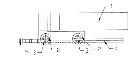
In drawings which illustrate embodiments of the invention. Figure 1 is a top
view of
one embodiment including a parting tool body (body) # I . washers #2, bolts #3
and an
inserted parting tool blade #4 with inserted carbide insert #5, Figure 2 is a
side view of
this embodiment, Figure 3 is a frontal view of this embodiment, Figure 4 is a
top view
of this embodiment without the parting tool blade, washers and bolts, Figure 5
is a
section of the line A-A of Figure 4, Figure 6 is a left side view of this
embodiment
(body # 1 ), Figure 7 is a frontal view of this embodiment (body # I ), Figure
8 is a bottom
view of this embodiment (body # 1 ), Figure 9 is left side view of this
embodiment (body
# 1 ), Figure I 0 is a section of the line B-B of Figure 9, Figure I I is a
rear view of this
embodiment (body # 1 ), Figure 12 is a top view of a component (washer #2) of
this
embodiment, Figure 13 is a side view of this component (washer #2), Figure 14
and I 5
illustrate the claims.
Figures 4 to 11 illustrate different views and sections of the embodiment
(body # I ). It is
constructed out of a single piece and the most important aspect is the unique
shape, as
illustrated by these drawings, which divides it into two main functions
sections. Section
K, shown in Figures 4 and S above the line A-A, is the portion which attaches
to the
tool post of the lathe via a clamping mechanism. Section K also contains a
slot F which
extends upward from the bottom of the unit. Section N in Figure 4 is where two
washers #2, as shown in Figures 1, 2. 3, I 2, and 13, clamp the parting tool
blades to the
unit. There are two counterbore holes which keep the washers #2 in the proper
position.
The washers #2 are then fastened to the unit with two regular socket head
bolts #3.
Sections K and N are connected to each other in only one location, as shown by
the
hatched area in Figure 4. The slot F in section K of Figure 5 is what gives
section N its
flexibility. The height of slot F and the thickness of the material above it
determine the
flexibility.
-2-
Representative Drawing
A single figure which represents the drawing illustrating the invention.
Administrative Status

For a clearer understanding of the status of the application/patent presented on this page, the site Disclaimer , as well as the definitions for Patent , Administrative Status , Maintenance Fee  and Payment History  should be consulted.

Administrative Status

Title Date
Forecasted Issue Date Unavailable
(22) Filed 1998-02-04
(41) Open to Public Inspection 1999-08-04
Dead Application 2002-02-04

Abandonment History

Abandonment Date Reason Reinstatement Date
2001-02-05 FAILURE TO PAY APPLICATION MAINTENANCE FEE

Payment History

Fee Type Anniversary Year Due Date Amount Paid Paid Date
Application Fee $150.00 1998-02-04
Maintenance Fee - Application - New Act 2 2000-02-04 $50.00 1999-02-03
Owners on Record

Note: Records showing the ownership history in alphabetical order.

Current Owners on Record
BAZYDLO, STEFAN
Past Owners on Record
None
Past Owners that do not appear in the "Owners on Record" listing will appear in other documentation within the application.
Documents

To view selected files, please enter reCAPTCHA code :


To view images, click a link in the Document Description column. To download the documents, select one or more checkboxes in the first column and then click the "Download Selected in PDF format (Zip Archive)" or the "Download Selected as Single PDF" button.

List of published and non-published patent-specific documents on the CPD .

If you have any difficulty accessing content, you can call the Client Service Centre at 1-866-997-1936 or send them an e-mail at CIPO Client Service Centre.


Document
Description 
Date
(yyyy-mm-dd) 
Number of pages   Size of Image (KB) 
Representative Drawing 1999-08-16 1 4
Abstract 1998-02-04 1 11
Description 1998-02-04 1 68
Claims 1998-02-04 1 21
Drawings 1998-02-04 4 59
Cover Page 1999-08-16 1 22
Abstract 1999-02-03 1 13
Description 1999-02-03 4 229
Claims 1999-02-03 1 37
Drawings 1999-02-03 8 103
Assignment 1998-02-04 2 59
Correspondence 1998-02-17 1 16
Correspondence 2001-11-06 3 276
Correspondence 2001-03-05 3 83
Correspondence 1999-02-03 2 55
Prosecution-Amendment 1999-02-03 15 412
Fees 1999-02-03 1 30