Note: Descriptions are shown in the official language in which they were submitted.
CA 02222711 1997-12-22
W O96/36;214 PCTAUS96/06324
FOOD PROCESSING VAT
Back~round of the Invention
The present invention relates generally to
the field oE food processing equipment and, more
particularl~y, to a food processing vat for production and
processing of semi-liquid food products, such as cheese.
The food processing vat of the present invention is
preferably ~-omprised of a closed vessel arranged in a
plurality of horizontally orientated, partial
frustoconic~l sections, each section having a separate
lo agitator means which allows maximum product yield to be
obtained from the raw materials used.
The use of totally enclosed food processing
vats, for the manufacture of many types of cheese and
similar semi~ uid food products, is well known in the
art. U.S. ]?atent Nos. 3,858,855; 4,206,880; 4,938,424
and 5,178,060 are examples of prior art cheese making
vats that are fully enclosed. The vats in each of these
patents use agitator means, for cutting the coagulum and
stirring, that are vertically disposed within a vessel
co~prised oi. two partial cylinders. This design is very
efEective for smaller vessels but becomes less efficient
with increases in size due to the need to create vertical
movement within the vat contents without generating
damagingly high peripheral agitator ~peeds. In the
paltents cited above, vertical movement is induced by
means of hinged deflector plates which cause m~X;mUm
turbulence ~rhen the agitator is rotated in the stirring
direction while maintaining a highly streamlined
configuration when the agitator is rotated in the cutting
direction.
U.S. Patent No. 4,108,058 discloses a fully
encllosed cheese making vat in the form of a horizontal
cy~indrical vessel with a single horizontal shaft
carrying the combined cutting and stirring paddles. The
construction of the agitator paddle results in less
damage to the food product and, in the case of cheese,
results in minimum release of butterfat and cheese fines
CA 02222711 1997-12-22
W O 961;~6214 PCT/US96/06324
into the whey. A major disadvantage of this design is
that the whole contents of the vat tend to rotate during
cutting and in effect move away from the knife blades.
This, together with a very high velocity gradient between
the agitator blades near to the shaft and those on the
periphery, makes it very difficult to achieve an evenly
cut coagulum and can cause problems of product
variability.
U.S. Patent No. 4,989,504 describes a fully
en,closed cheese making vat in the form of a plurality of
hc,rizontally arranged partial cylindrical sections each
with a separate shaft-mounted agitator, such that the
distance between agitator shafts is greater than the
radius of the swept volume created by the rotation of the
aqitator. This arrangement is a significant improvement
over the single shaft horizontal vat, but the problem of
velocity gradient between the agitator paddle near to the
shaft and that at the periphery is only slightly reduced.
The low agitator speeds that are typically used with this
type of food processing vat give rise to very poor
agitation adjacent to the agitator shaft and can also
cause a significant problem with product congealing
around the shaft. An additional problem with this
arrangement is the extreme difficulty encountered when
elltering the vat for maintenance or hand cleaning due to
the impossibility of parking the agitator paddles in a
position that allows easy and safe movement around the
inside of the vat.
Although the designs listed above have proved
adequate for processing many types of cheese products,
modern commercial practice has generated more stringent
compositional standards and the requirement for many
customized products with special functional properties.
Some of these functional properties result in significant
production difficulties, especially where it is required
to effect partial separation of solid from liquid while
maintaining some degree of agitation to prevent the
CA 022227ll l997-l2-22
W 096/36214 PCT~US96/06324
matting together of solid mate~ial that takes place if
there is no agitation.
In order to achieve the required standard of
operation, it would be advantageous to have a horizontal
food processing vat that further reduced problems
associated with velocity gradients across the agitator
that eliminated the requirement for horizontal shafts
r~mning through the center of the swept volumes and that
pe~rmitted partial separation of solid from liquid during
mailltained agitation.
Sl ~-Y of the Invention
The present invention is directed to an
encLosed fc~od processing vat comprised of a horizontally
oriented vat having two or more generally cylindrical
wall portions, each wall portion comprising the first
por~ion of a swept volume created by the rotation of an
agitator means about a horizontal axis.
The horizontal axis is disposed centrally
within each wall portion the distance between the axes
being smaller than the radius of the swept volume created
by rotation of the agitator means so that a second
portion of the swept volume for each axis intersects and
overlaps the swept volume of adjacent axis. The vat is
enclosed by- a pair of end walls and common top and bottom
walls. In the preferred embodiment the generally
cylindrical wall portions comprise a pair of intersecting
truncated cones that have their maximum radius at, or
near, the center of the vat allowing the contents of the
vat to drain towards the center and eliminating the need
to slope the vats towards an end outlet.
Each horizontal axis is provided with an
agitator means comprised of a combined cutting and
stirring panel carried on two support arms that extend
radially from the axis and which are supported by stub
sha~ts that are concentric with the axis. Each agitator
panel is ccmprised of a series of blades arranged to
provide an open framework of intersecting blades which do
CA 02222711 1997-12-22
W O 961r36214 PCT~US96/06324
not need to be orthogonal and, preferably, are neither
di.rectly perpendicular to the axis nor directly parallel
thereto. The innermost generally parallel blade is
mounted part way up the radial support arms and is
angularly disposed such that it forms a shallow V-shape
wi.th the apex of the V pointing radially outwardly. The
outermost generally parallel blade is arranged to run
acljacent to the inner wall of the vat throughout part of
it:s rotation and is also angularly shaped to form a
shallow V similarly shaped and parallel to the innermost
blade. Agitator panels are tapered in a radial direction
and converge towards the periphery so that when rotated
co-directionally the outer portion of each panel may pass
between the radial supports of an adjacent panel.
The blades are sharpened on one side only and
f:Lxed in such a way that if the agitator means is rotated
in one direction the sharp edges will be presented to the
food product and cutting will take place, whereas, if the
agitator means is rotated in the opposite direction the
b:Lunt edges of the blades will be presented to the food
product and stirring will take place. Stirring action is
enhanced by provision of fixed deflector plates which
generate turbulence when the agitator panel is rotated in
the stirring direction while maintaining a sharp,
sl:reamlined profile when the agitator is rotated in the
clltting direction.
The overall agitation pattern is such that
the contents of the vat will be induced to rotate in the
same direction as the agitator with significant cross-
clltting action and other interactions in the zone wherethe agitator panels overlap. The present invention
allows rotation of product to be more easily induced than
in food processing vats where through shafts dictate that
a:~is of rotation of adjacent agitators is spaced further
apart than the radius of the swept volume. This is
c:eitical to effective control of the early stages of
cutting the coagulum in cheese making and allows the
CA 02222711 1997-12-22
W 096136214 PCTAUS96/06324
agi~ators of the present invention to be operated at
lower speeds, causing less product ~amage, than would
otherwise b~e possible.
~he velocity gradient between the inner and
outer parallel knives is significantly reduced due to the
eliTnination of the through shaft and radially inner
padclle components and this also removes any tendency for
a~cumulation of congealed product as the innermost
pa~rallel knife moves at a velocity sufficient to prevent
ad~hesion during all cutting and stirring operations.
Wh,ere an agitator panel passes between the radial
supports of an adjacent agitator panel, the shear forces
on,t:he product are reduced because both panel and radial
supports are moving in the same direction, thus product
damage is minimized. Agitator panels are driven by power
app]ied to the drive and stub shaft which is carried
through the end wall of the vat and externally supported.
Product is retained within the vat by means
of a hygienic seal between the end wall of the vat and
the driven stub shaft. Agitators normally rotate co-
directionally but can be arranged for counter rotation
where specific production criteria demand it. Agitators
can be operated in a reciprocating or oscillating mode at
certain stages of production. The non-drive end of the
agitator pa~nel is supported by means of a hygienic
internal bearing which engages the non-driven stub shaft.
An outer shell surrounds these parts of the inner wall
sections, that are below the normal level of product in
the vat, and is supported by a cradle structure for
stabilizing the vat.
Heating or cooling of the contents of the vat
can take place by means of the application of heating or
cooling media applied to the space between the inner wall
an~ the outer shell of the vat. Provision is made for
filing and emptying the vat by means of suitable
connection ~hrough the vat walls. Partial separation of
solid material from liquid may be made by means of
CA 02222711 1997-12-22
W O96/.36214 PCTrUS96/06324
connections through the vat ends at various levels. If
it; is necessary to effect this separation while the
contents are exposed to continuous agitation, the
ac~itator may be set in reciprocating mode and a suction
p:ipe and solids exclusion screen lowered into the vat
from the top. Access to the inside of the vat, for
inspection and maintenance, can be gained through a
sealable opening in the top or end wall.
Accordingly, a primary objective of the
lo p:resent invention is to provide an enclosed food
p:eocessing vat that maintains the highest level of
protection against risk of external contaminants entering
the food product, minimizes mechanical damage to the food
product and allows maximum control of the food
manufacturing process.
Another objective of the present invention is
to provide an enclosed food processing vat having a
plurality of horizontally disposed agitator paddles,
without through shafts, that provide means for cutting
and stirring the food product such that the velocity
gradient across agitator panel is minimized and
collection of congealed product around through shaft is
eliminated.
A further object of the present invention is
to provide a food processing vat where partial separation
of solid from liquid product can be undertaken while
maintaining some agitation to prevent solids from matting
t:ogether.
These and other objectives of the present
i.nvention will become apparent with reference to the
clrawings, the description of the preferred embodiment and
t:he appended claims.
Brief Description of the Drawinc~s
FIG. 1 is an end elevation of the processing
vat of the present invention with a portion of one end
wall broken away to show the agitator panels therein.
CA 02222711 1997-12-22
W O 916136214 PCTAUS96/06324
FIG. 2 is a horizontal sectional view through
the processing vat shown in FIG. 1 with the agitator
panels rotationally displaced 90~ to show their
int:eraction.
FIG. 3 is a perspective view of one of the
agitator panels of the present invention.
FIG. 4 is a top plan view of the agitator
panel, also showing details of the rotary seal for the
dri.ven panel stub shaft.
FIG. 5 is an inner end elevation of the
agi.tator panel shown in FIG. 4.
FIG. 6 is a sectional view taken on line 6-6
of FIG. 4.
FIG. 7 is a sectional view taken on line 7-7
of FIG. 4.
FIG. 8 is a partial sectional view taken on
line 8-8 of FIG. 4.
FIG. 9 is a sectional view through the
agi.tator panel taken on line 9-9 of FIG. 4.
FIG. 10 is an enlarged detail of a portion of
the rotary seal shown in FIG. 4.
Detai~Led Descril~tion of the Preferred Embodiment
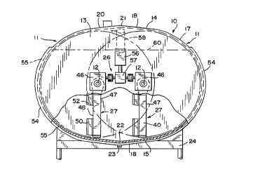
The food processing vat 10 of the present
in~rention, as shown in FIGS. 1 and 2, is completely
enc:losed and is formed from a pair of generally
cylindrical wall portions 11 which are positioned with
their axes 12 disposed generally horizontally and in
par-allel horizontally spaced relation. The axial ends of
the wall portions 11 are interconnected and enclosed by
opposite end walls 13 and the surfaces of the wall
portions 11 are interconnected with generally
- tangentially disposed upper and lower walls 14 and 15,
respectively. Thus, the vat 10 has a generally oval
cross section when viewed in a plane perpendicular to the
axes 12.
In the preferred embodiment of the invention,
eac:h of the cylindrical wall portions 11 is constructed
CA 02222711 1997-12-22
W O96;/36214 PCT~US96/06324
of a pair of interconnected and oppositely extending
frustoconical surface portions 16. The frustoconical
surface portions are interconnected along a central
circular apex 17 which lies in a plane perpendicular to
t]ne axes 12 and defines the region of maximum vat radius
with respect to each of the axes 12. Similarly, the
u~pper wall 14 and lower wall 15 each comprise a pair of
o]ppositely sloping planar wall portions 18 interconnected
along abutting edges to form central linear ridges 20
interconnecting the circular apices 17 at the top and
bottom of the vat. The wall portions 18 also preferably
slope in the direction of the central linear ridge 20 to
form central lateral ridges 21. This construction is
particularly useful for the lower wall 15 where a central
apex 22, formed at the intersection of the lower central
linear ridge 20 and the lateral ridges 21, provides a
convenient position for a drain outlet 23. The vat is
mounted on a supporting frame 24 with the central drain
outlet 23 establishing the lowermost point of the vat.
The supporting frame 24 includes a side frame member 25
which supports a drive mechanism 26 for the vat, as will
be described hereinafter.
Referring also to FIGS. 3 and 4, a pair of
agitator panels 27 are rotatably mounted within the vat
10, each panel 27 having its rotational axis coincident
with an axis 12 of one of the generally cylindrical wall
portions 11. Each of the panels 27 is constructed of an
open framework of intersecting blades 30 comprising
generally flat plates 28. The blades include a number of
parallel generally radially extending blades 31 and a
number of parallel generally axially extending blades 32
which are preferably arranged such that the radially and
axially extending blades are respectively non-
p,erpendicular. As shown, the framework of intersecting
blades comprises primarily a plurality of frame segments
of parallelogram shape. As best seen in FIGS. 2 and 4,
t;he generally radially extending blades 31 are arranged
CA 02222711 1997-12-22
W O9~/36:~14 PcTruS96/06324
in. a pair of radial blade groups 34 with one of the
groups positioned on each side of a central vertical
plane perpendicular to the panel axis 12. The radially
extending blades 31 of each blade group 34 are set at an
acut:e angle to the vertical central plane and are
mu.tually divergent in a radially outward direction.
The generally axially extending ~lades 32
in,clude an outermost blade 35 which comprises the
radially outer edge of the agitator panel 27 and an
lo in,nermost blade 36 which comprises the radially inner
edge of the panel. A number of intermediate axially
ex:tending blades 37 are generally equally spaced between
an,d parallel to the outermost and innermost blades 35 and
36.
To allow the rotating agitator panel 27 to
sweep in closely spaced relation to the frustoconical
su.rface portions 16 of the vat, and also to provide the
un.ique intersecting overlap of the respective volumes
wh.ich are swept by the rotating agitator panels, the
outermost and innermost blades 35 and 36, respectively,
have a shallow V shape each of which defines a central
blacle apex 38 which points radially outwardly, allowing
the outermost blade .35 to conform closely to the shape of
the interior of the frustoconical surface portions 16.
Each agitator panel 27 includes a pair of
radi.al support arms 40 by which the panel is mounted for
rotation. One end of one of the support arms includes a
first hub 41 rotatably supported by a bearing 42 on one
of t:he end walls 13. The end of the other support arm 40
includes a second hub 43 which is rotatably supported to
turn in a rotary seal 44 in the other end wall 13 and is
- also attached to a stub shaft 45 extending from a right
angle gear box 46 forming part of the drive mechanism 26.
The opposite outer ends of the support arms 40 are
secured to the opposite ends of the outermost blade 35.
The rotatio:nal axes 12 of the agitator panels 27 are
spac:ed horizontally at a distance which is less than the
CA 02222711 1997-12-22
W O96/36214 ; PCTrUS96/06324
radius of rotation (or the radius of the volume swept) by
th~e panels as they rotate. Therefore, to prevent contact
between the rotating panels, the innermost blade 36 is
spaced radially from the axis of panel rotation by an
amDunt sufficient to accommodate an overlap in the
respective volumes swept by each panel as it rotates
beyond the axis of the adjacent panel. As a result, the
radially outer edge portion of one panel, defined by the
position of the outermost blade 35, will pass during
rotating through the space between the innermost blade 36
and rotational axis 12 of the other panel.
In a manner generally similar to prior art
cheese processing vats, the agitator panel blades 30 are
constructed to provide a cutting function when the panels
are rotated in one direction and a stirring function when
the panels are rotated in the opposite direction. Thus,
each of the blades has a sharp cutting edge 47 on one
side of the panel, which cutting edges are preferably
coplanar, and a blunt stirring edge 48 on the other side
of' the panel, which stirring edges may be coplanar, but
are not in the preferred embodiment. In order to provide
adeguate panel strength, the radial support arms 40
(which also are provided with cutting edges 47 and
st:irring edges 48), all of the generally axially
e~tending blades 32, and certain of the generally
radially extending blades 31 are constructed of heavier
p].ate material than the remaining intermediate radially
e~tending blades 39. As best shown in FIGS. 3 and 9, the
intermediate radial blades 39 are also narrower in depth
and~ as a result, have stirring edges 48 which are offset
inwardly of the corresponding stirring edges of the
b:Lades 32. Nevertheless, all of the blades are provided
w:ith cutting and stirring edges.
The radially outer ends of alternate radially
e~tending blades 31 and the outer ends of each radial
support arm 40 include integral deflector plates 50 each
O:e which includes a face portion 51 bent out of the plane
CA 02222711 1997-12-22
W O9~;/36214 P ~ AUS96~6324
oi-~ the bla~e on which it is formed and disposed at an
acute angle with respect thereto. The deflector plates
5() extend from the stirring edge face of the agitator
panel 27 and the free edges thereof are blunt in the same
manner as t.he stirring edges 48. A pair of inner
def:lector p,lates 52 are also provided on shortened radial
b]Lades 53 mlounted near the intersections of the radial
s~lpport arm.s 40 and the opposite ends of the innermost
b].ade 36.
It is important, when utilizing the food
processing vat of the present invention to make cheese,
to ~et the coagulated mass of curds and whey moving in a
slo~ circulatory path under the influence of the rotating
a~ ator panels 27, both rotating in the same direction
wi.th the cutting edges 47 leading. Low speed circulation
of ~:he coagulated mass, by rotating the agitator panels
in the range of l to 2 rpm, is attained more rapidly in
this horizontal vat construction, as compared to prior
art devices such as those discussed above, because the
axicllly extending ridge or apex defined by the juncture
bet~reen the two cylindrical shells of prior art vats is
eliminated. Elimination of this ridge eliminates a
significant obstruction to circulatory flow of the
coagulated mass. Once initial slow circulatory movement
is attained, the rotational speed of the agitator panels
is i.ncreased, to say 4 to 5 rpm, and cutting of the mass
is commenced. A most important aspect to the present
invention i6 the elimination of through-shafts for the
rotating agitator panels and the radial offset of the
innermost blade 36 which allows the close spacing of the
two axes 12 and the overlap of the outer edge of one
- agit.ator panel into the space along the rotational axis
of the other, once during each revolution. Furthermore,
the divergent orientation of the radially extending
blad.es 3l in each of the blade groups 34 results in a
cross-cutting of the coagulated mass as one agitator
panel rotates downwardly through the mass lying between
CA 02222711 1997-12-22
W O 96/36214 PCTrUS96/06324
the two axes 12 immediately after upward passage of the
ot:her agitator panel through that mass. Such cross-
cutting significantly enhances the cutting efficiency and
quality .
The foregoing construction also inherently
e]iminates the low velocity cutting regions adjacent the
through-shafts of prior art constructions. Also
e].iminated are the essentially zero velocity regions on
the shaft which permit a build-up of the material being
processed.
The deflector plates 50 trail when the
ac~itator panels 27 are being rotated in the cutting
diLrection. Although the movement of the deflector plates
through the mass of curds and whey is quite smooth in the
cutting direction, the angled offset face portions 51
nevertheless contact the coagulated mass and provide
beneficial movement of the mass in both the radial and
a~ial directions. This enhanced movement is particularly
important to eliminate tracking of the cutting blades 30
through essentially the same cuts in succeeding
revolutions. If tracking occurs, the mass will tend to
be cut into narrow slivers instead of the larger and more
desirable cubical masses. When rotation of the agitator
panels is reversed for stirring, the deflector plates 50
aLso provide the same dual direction flow in both radial
and axial directions to better enhance the uniformity of
the cut mass. The cheese is also typically heated during
stirring and the unique angled orientation of the
deflector plates assists greatly in removing the warmer
mass from the heated side walls of the vat and replacing
it with cooler mass from the interior.
Substantially the entire vat is enclosed by
an outer wall 54 which defines with the generally
cylindrical wall portions 11, the end walls 13 and the
lower wall 15 a heating and cooling jacket 55. The upper
wall 14 is not enclosed by the outer wall 54 and this
unjacketed area is generally above the level of the
CA 02222711 1997-12-22
W O96J36:214 PCTrUS96/06324
13
liquid and semi-liquid materials being processed. The
heating and cooling jacket 55 may be supplied with a
cooling fluid, hot water or steam and, by substantially
enclosing the entire vat in the heating and cooling
jacket 55, combined with the unique radial and axial flow
induced by ~he angled deflector plates 50, most effective
and efficient cooking of the cheese mass or other
te~perature control may be attained. Furthermore, the
jacket portions adjacent the end walls 13 may be
separated from the jacket portions surrounding the
generally c~lindrical wall portions, so they may be
separately supplied with heating or cooling fluid to
provide even greater selectivity in the control of
temperature.
The drive mechanism 26 includes an electric
motor 56 dri.ving a reducer 57 which, in turn, is coupled
to the right: angle gear boxes 46 for the stub shafts 45.
In addition to the usual variable speed rotation of the
agitator panels in the cutting and stirring directions,
the ,drive mechanism 26 may be operated to provide a
reciprocal or oscillating agitator panel movement to
enhance intermediate draw-off of whey during the
proc~essing. In particular, the agitator panels may be
driv,en to oscillate through acute angles below the
horizontal just sufficient to prevent the mass from
ma1:t.ing whil.e surface liquid is drawn off. A strainer
apparatus 58 may be operatively attached to the upper
wall 14 of the vat to be lowered below the upper level 60
of the whey, while the agitator panels 27 are stationary
or are being oscillated in the lower portion of the vat,
to permit wh.ey to be drawn off while excluding solids.
Referring to FIGS. 4 and lO, the drive
connection between ~he second hub 43 of each agitator
panel 27 and the stub shaft 45 must necessarily pass
throllgh the end wall 13 of the vat and, as a result, the
int:e~face is sealed with the rotary seal 44. The
peri}?heral edge of a circular opening in the end wall 13
CA 02222711 1997-12-22
W O 96,'36214 PCTrUS96/06324
14
is secured, as by welding, to an annular retaining flange
61. The retaining flange 61 surrounds the hub 43 and
includes an inner shoulder 62 adapted to receive a
flexible annular seal 63. The seal 63 is captured and
held in a recess formed by the shoulder 62 and the face
of an annular cover flange 64. The cover flange is
at:tached to the retaining flange 61 with a series of
ciLrcumferentially spaced bolts 65 and associated washers
66 (only one set of which is shown). A pair of 0-rings
6'7 positioned in suitable grooves in the respective
f:Langes 61 and 64 help seal the annular seal 63 against
peripheral by-pass of liquid and help to maintain the
seal with misalignment in the hub 43 as it rotates. The
rotary contact surface of the main annular seal 63
imclu des a flexible lip 68 and a heel 70.
In an alternate construction, one of the
blade groups 34 of the agitator panel may be positioned
rDtationally 180~ from its position in a panel 27 of the
preferred embodiment. This would create a sort of crank
configuration to the agitator panels which might be
desirable for certain types of processing. A central
strut or similar support to provide rotational support
between the hubs 41 and 43 might extend from one or more
interior wall portions between the offset blade groups.