Note: Descriptions are shown in the official language in which they were submitted.
CA 02222819 2001-05-03
25986-34
- 1 -
METHOD AND DEVICE FOR PRODUCING AND
UTILIZING GAS FROM WASTE MATERIALS
The invention pertains to a process and a device for
producing and utilizing gas from waste materials, in which the
waste materials are transported along a grate in a furnace and
combustion air is added.
From patent DE 42 20 265 C1 a process of this type is
known in which the waste materials pass sequentially through a
drying zone, a carbonizing zone, a reduction zone and an
oxidation zone, in order to achieve combustion and coking
toward the end of the grate. In this process large proportions
of slag are formed, which must be broken up by crushing rollers
of correspondingly large dimensions. The energy needed for the
gasification process is conveyed to the waste material through
convection and radiation by the combustion which occurs at the
end of the grate, via the combustion air which is introduced
for the most part above the grate. This requires an especially
strong combustion process at the end of the grate, with the
corresponding formation of coke and slag.
Summary of the Invention
In a process for producing and utilizing gas from
waste materials, there is provided an arrangement of undergrate
forced-draft chambers, at least in the longitudinal direction
of a firing grate, charged with combustion air. Waste
materials are ignited in a charging area of the grate in the
presence of a superstoichiometric level of oxygen; and in the
direction of slag removal-combustion is limited to a
substoichiometric level, which is required for gasification of
the combustible components.
CA 02222819 2000-07-31
25986-34
- 2 -
More particularly, there is provided a process a
process for creating and utilizing gas from waste material
comprising: (a) igniting the waste material in a charging area
of a firing grate in a furnace in the presence of a
superstoichiometric level of oxygen; (b) conveying the waste
material along the grate in a direction of slag removal; and,
(c) incinerating the waste material in the direction of slag
removal at a substoichiometric level of oxygen which results in
gasification of combustible components of the waste material to
produce a waste gas, wherein undergrate forced-draft chambers
disposed at least longitudinally to the grate supply air to the
waste material.
There is also provided a furnace comprising: (a) a
fuel charging system; (b) a firing grate that receives waste
material from the fuel charging system; (c) undergrate forced-
draft chambers disposed at least longitudinally to the grate
for supplying air to the waste material; and (d) a slag removal
system that receives slag from the grate, wherein the
undergrate forced-draft chambers have lines for introducing
oxygen.
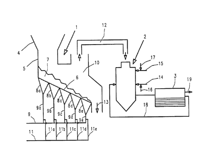
Brief Description of the Drawing
The figure depicts a furnace in combination with a
second furnace and a heat exchanger for producing and utilizing
gas from waste materials.
Description of the Preferred Embodiments
In this process the energy needed for gasification is
not introduced from outside through excessively vigorous
combustion at the end of the firing grate, and hence through
heating of the combustion air and through radiant energy from
the roof area which has been heated up by this incineration;
CA 02222819 2000-07-31
25986-34
- 2a -
instead this gasification energy comes from the incineration of
the waste materials, which are continuously ignited in the
charging area of the grate under superstoichiometric conditions
and then continue to be incinerated under substoichiometric
conditions. As a result there is always an adequate supply of
energy available, making possible a stable combustion process
which leads to good ash burnout and to avoidance of pyrolysis
coke in the left-over residue. Since the necessary energy
comes from the fuel as a result of its ignition, and does not
need to be transferred to the waste materials from outside,
this yields a greater degree of efficiency, with the result
that it is no longer necessary to burn so much of the waste
material to generate energy for the gasification process, so
that a larger quantity of usable gas can be created.
These beneficial effects are still further enhanced,
under a refinement of the invention, by adding oxygen to the
gasification air at a substoichiometric level after the waste
materials are ignited.
CA 02222819 1997-11-28
_3_
The advantage of this measure is that the quantity of gasification air, and
hence the quantity of
nitrogen which functions as ballast, can be reduced very significantly, which
leads to a number
of benefits. One of the benefits is that as a result of the smaller quantity
of gasification air the
flow speed through the bed of the fuel mass is lowered, which leads to a
noticeable reduction in
the flow of airborne dust. An additional substantial advantage is that
lowering the proportion of
nitrogen reduces the formation of nitrogen oxides. There continues to be a
relatively large
measure of energy available for the gasification, since it is no longer
necessary to heat up so
much nitrogen, which is present in the gasification air only as ballast.
The gasification is preferably carned out in such a way that the gasification
temperature of the
substances to be gasified is 600 to 850°C, and the air ratio needed to
achieve substoichiometric
gasification is 0.4 to 0.8.
The gases which are produced can be used in a great variety of ways.
Preferably, provision is
made to use the created gases by burning exclusively the combustible
components which come
from the first furnace in a second furnace which is connected to the first
either directly or by a
gas extraction system. This procedure depends primarily upon the oxygen
content and the
calorific value of the gases coming from the first furnace.
If the oxygen content of the waste gases coming from the first furnace is not
sufficiently high, in
order to achieve complete combustion it is beneficial to add combustion air in
the form of
ambient air to the waste gas coming from the first furnace.
CA 02222819 1997-11-28
-4-
On the other hand, if the calorific value of these gases is not su~cient to
enable the necessary
incineration at a higher temperature, then in a refinement of the invention a
higher-grade
combustible gas can be added to the combustible components in the second
furnace, in
accordance with their calorific value, along with the combustion air.
To achieve higher combustion temperatures in the second furnace than is
possible with ambient
air, there is benefit in mixing oxygen with the combustion air for the second
furnace andlor to the
higher-grade combustible gas, in a refinement of the invention. The
introduction of oxygen in
addition to the combustion air has the advantage that the quantity of
combustion air which needs
to be added can be kept down, which allows the quantity of waste gas from the
second furnace to
be reduced.
If there is sufficient oxygen present in the waste gas coming from the second
furnace, and if the
calorific value is also sufficiently high, waste gas which is taken from the
waste gas stream after
cooling in a waste heat recovery system can be introduced for mixing and
burning the gases in
order to regulate the combustion in the second furnace. This procedure has the
advantage that
any gases which may still be combustible when they leave the second furnace
are burned in
addition; and furthermore the quantity of waste gas is lower compared to the
procedure in which
a higher-grade combustible gas is added.
The incineration in the second furnace is carried out by selecting from the
measures described
above, preferably in such a way that in the second furnace the air ratio is
1.1 to 1.8. The
combustion temperature of the gases in the second furnace is 950 to
1250°C.
CA 02222819 1997-11-28
' " _5_
The device for carrying out the process is characterized by the fact that in a
furnace which
comprises a fuel charging system, a grate with undergrate forced draft
chambers subdivided in
the longitudinal direction and possibly also in the transverse direction, and
a slag removal
system, the forced draft chambers have lines for the introduction of oxygen.
This makes it
possible to regulate the gasification with a fine touch, and furthermore with
smaller quantities of
waste gas compared to the exclusive use of ambient air for the gasification
process.
If utilization of the generated gases by burning is planned, then the
invention provides for
connection of a second furnace with the first furnace, either directly or
through a waste gas flue.
This prevents any significant cooling of the combustible gases which arise in
the first furnace,
and consequently the combustion in the second furnace can be carried out at a
relatively low
excess air ratio, in many cases even without additional sources of energy, at
such high
temperatures that all of the organic components in the combustible gas can be
broken down
without promoting the formation of nitrogen oxides, since the temperature in
the second furnace
is kept at a level which is lower than a critical temperature limit at which
greater quantities of
nitrogen oxides begin to be formed.
In order to be able to carry out the advantageous refinements of the process,
advanced
implementations of the device provide for the second furnace to be equipped
with at least one
line for the introduction of combustion air, at least one line for the
introduction of a higher-grade
combustible gas, or at lease one line for the introduction of recirculated
waste gas. These three
measures can optionally be provided individually or in combination, depending
upon the type of
implementation.
CA 02222819 2000-07-31
25986-34
- 6 -
The invention is explained in additional detail below
on the basis of a sample implementation shown in the drawing,
the only figure of which is a schematic representation of a
furnace with a second furnace connected to it.
As can be seen from the drawing, the device for
carrying out the process comprises in its essentials a furnace
which is identified in its entirety as l, as used heretofore
for waste incineration, in combination with a second furnace 2
functioning as an afterburner chamber, followed by a heat
exchanger 3. The other requisite devices, especially for
cleaning the waste gases, are not shown in this drawing, since
they are part of the current technology of furnaces.
The first furnace 1 comprises a charging funnel 4
with adjacent charging chute 5, by means of which the waste
materials which are to be burned are conveyed to a firing grate
6; the waste materials on the firing grate 6 are designated as
7. Beneath the firing grate 6 there are individual forced
draft chambers 8a to 8e, through which air is introduced from a
supply line 9 through lines 9a to 9e. The air passes through
the grate 6 into the combustion chamber 10. Through the forced
draft chambers 8a and 8b combustion air is supplied, possibly
mixed with oxygen, in order to ignite the waste materials in a
superstoichiometric atmosphere. After this initial phase of
ignition air is conveyed to the grate through the forced draft
chambers 8c to 8e as gasification air, preferably mixed with
oxygen, with the quantity of gasification air and the quantity
of oxygen adjusted so that the gasificaiton takes place
substoichiometrically with an air ratio of ~ = 0.4 to 0.8.
Oxygen is conveyed to the individual forced draft chambers
through the lines lla to lle,
CA 02222819 1997-11-28
_ 'J _
which are fed from a common line 11 and merge into the lines 9a to 9e. To
regulate the
respective quantities, both the lines 9a to 9e and the lines 11 a to 11 a are
fitted with valves, which
are not shown. Thus the additional introduction of oxygen leads not only to an
increase in the
proportion of oxygen in the supplied air, but at the same time also to a
reduction in the
proportion of nitrogen. The gasification is carried out in such a way that
temperatures between
600 and 850°C occur. The resulting combustible gas is conducted, with
practically no loss of
heat, by means of a waste gas flue 12 leading from the furnace, to the second
furnace 2, which
takes the form of an afterburner chamber. The slag which arises in the
gasification process leaves
the furnace by a slag removal system 13.
In the second furnace 2 the excess air ratio is adjusted to between 1.1 and
1.8, preferably at 1.2,
by introducing combustion air through a line 14. The resulting temperatures
are in the range of
950 to 1250°C. If the gas to be burned, coming from the first furnace
1, has too low a calorific
value, an additional line 15 is provided for the introduction of high-grade
combustible gas, such
as natural gas. Both the line 14 for combustion air and the line 15 for higher-
grade gas can have
lines 16 and 17 connecting to them for additional oxygen. An additional line
18 can be provided
in order to introduce recirculated waste gas into the second furnace 2; this
recirculated waste gas
is cooled to a temperature below 300°C after having passed through the
heat exchanger 3. This
recirculated waste gas is thoroughly mixed with the combustible gas in the
second furnace 2,
avoiding the introduction of too much combustion air, which would be needed to
create
turbulence and which would increase the quantity of waste gas and also the
temperature which
occurs in the second furnace. At the same time any combustible components
which are still
CA 02222819 2000-07-31
25986-34
_ g _
present in this waste gas can be burned. The gases coming from
the heat exchanger 3 are conducted through a line 19 to an
exhaust gas cleaning system, which is not shown because it is
generally known.