Language selection

Search

Patent 2222953 Summary

Third-party information liability

Some of the information on this Web page has been provided by external sources. The Government of Canada is not responsible for the accuracy, reliability or currency of the information supplied by external sources. Users wishing to rely upon this information should consult directly with the source of the information. Content provided by external sources is not subject to official languages, privacy and accessibility requirements.

Claims and Abstract availability

Any discrepancies in the text and image of the Claims and Abstract are due to differing posting times. Text of the Claims and Abstract are posted:

  • At the time the application is open to public inspection;
  • At the time of issue of the patent (grant).
(12) Patent: (11) CA 2222953
(54) English Title: AERATOR CONTROL MECHANISM
(54) French Title: MECANISME DE COMMANDE D'AERATEUR
Status: Deemed expired
Bibliographic Data
(51) International Patent Classification (IPC):
  • A01B 45/02 (2006.01)
  • A01B 71/00 (2006.01)
(72) Inventors :
  • TEIGA, MICHAEL TIMOTHY (United States of America)
  • SIMON, MERLIN EMMET (United States of America)
  • LAMB, MARK EDWARD (United States of America)
(73) Owners :
  • DEERE & COMPANY (United States of America)
(71) Applicants :
  • DEERE & COMPANY (United States of America)
(74) Agent: BORDEN LADNER GERVAIS LLP
(74) Associate agent:
(45) Issued: 2001-08-07
(22) Filed Date: 1997-12-18
(41) Open to Public Inspection: 1998-08-05
Examination requested: 1997-12-18
Availability of licence: N/A
(25) Language of filing: English

Patent Cooperation Treaty (PCT): No

(30) Application Priority Data:
Application No. Country/Territory Date
08/795,093 United States of America 1997-02-05

Abstracts

English Abstract


A control mechanism for an aerator mechanism, the control mechanism being
coupled with the engine for automatically slowing the engine when the aerator mechanism is
shifted between transport and operating positions. The engine control mechanism includes
a solenoid coupled with an operator engagable position control mechanism and an arm of
an engine governor such that the governor will slow the engine when the position control
mechanism is engaged to shift the aerator mechanism between transport and operating
positions.


French Abstract

Mécanisme de commande de mécanisme d'aérateur. Ce mécanisme de commande est relié au moteur pour ralentir automatiquement celui-ci lorsqu'on déplace ce mécanisme d'aération de sa position de transport à sa position de fonctionnement. Ce mécanisme de commande du moteur dispose d'un solénoïde, relié à un mécanisme de commande de position pouvant être actionné par l'opérateur, et d'un bras de régulateur de régime fonctionnant de manière à ralentir le moteur lorsque le mécanisme de commande de la position est utilisé pour faire passer le mécanisme d'aération de sa position de transport à sa position de fonctionnement.

Claims

Note: Claims are shown in the official language in which they were submitted.


The embodiments of the invention in which an exclusive property or privilege
is
claimed are defined as follows:
1. A mechanism adapted for use with a vehicle having a vehicle power source,
said
mechanism comprising:
an aerator mechanism having tines operatively driven by the power source up
and
down into and out of engagement with the ground during operation, said aerator
mechanism
being shiftable between a raised transport position and a lowered operating
position,
a position control mechanism engagable by an operator for shifting the aerator
mechanism between the transport and operating positions, and
power source control means coupled with the vehicle power source for
automatically
slowing the vehicle power source when said aerator mechanism shifts between
the
transport and operating positions, and said power source control means is
deactivated when
the aerator mechanism reaches the transport and operating positions.

2. The invention of claim 1, wherein said power source further comprises an
engine,
and
said power source control means further comprises a solenoid operatively
coupled
with the position control mechanism and an arm of a governor for the engine
such that the
governor will slow the engine when the position control mechanism is engaged
for shifting
the aerator mechanism between the transport and operating positions.

3. The invention of claim 1, and further comprising a resilient constraint
coupled with
the aerator mechanism for limiting shifting of the tine during operation.

4. The invention of claim 3, wherein said resilient constraint biases the
tines toward
a proper position when the tines are disengaged from the ground.

5. A mechanism adapted for use with an aerator having an engine, said
mechanism
comprising:
an aerator mechanism having tines which shift up and down into and out of
engagement with the ground during operation, said aerator mechanism being
shiftable
between a raised transport position and a lowered operating position,
a resilient constraint coupled with the aerator mechanism for limiting
shifting of the
tine during operation,
a position control mechanism engagable by an operator for shifting the aerator
mechanism between the transport and operating positions, and
engine control means coupled with the engine for automatically slowing the
engine
when said aerator mechanism shifts between the transport and operating
positions and said


6


engine control means is deactivated when the aerator mechanism reaches the
transport and
operating positions, said engine control means further comprises a solenoid
operatively
coupled with the position control mechanism and an arm of a governor for the
engine such
that the governor will slow the engine when the position control mechanism is
engaged for
shifting the aerator mechanism between the transport and operating positions.

6. The invention of claim 5, wherein said resilient constraint biases the
tines toward
a proper position when the tines are disengaged from the ground.

7. A mechanism adapted for use with a vehicle having a vehicle power source,
said
mechanism comprising:
an aerator mechanism having tines operatively driven by the power source up
and
down into and out of engagement with the ground during operation, said aerator
mechanism
being shiftable between a raised transport position and a lowered operating
position,
a position control mechanism engagable by an operator for shifting the aerator
mechanism between the transport and operating positions, and
a tine speed control mechanism operatively coupled with the position control
mechanism and the aerator mechanism such that the control mechanism slows the
up and
down shifting of the tines when the aerator mechanism is shifting between the
transport and
operating positions, and the tine speed control mechanism is deactivated when
the aerator
mechanism reaches the transport and operating positions.

8. The invention of claim 7, wherein said control mechanism further comprises
a
solenoid operatively coupled with the position control mechanism such that the
solenoid
initiates slowing of the up and down shifting of the tines when the aerator
mechanism shifts
between the transport and operating positions.

9. The invention of claim 8, wherein said control mechanism further comprises
a
governor coupled with the solenoid, said governor being operatively coupled
with the vehicle
power source for slowing the vehicle power source and tines driven thereby
when the
aerator mechanism shifts between the transport and operating positions.

10. The invention of claim 9, and further comprising a resilient constraint
coupled
with the aerator mechanism for limiting shifting of the tine during operation.

11. The invention of claim 10, wherein said resilient constraint biases the
tines
toward a proper position when the tines are disengaged from the ground.

12. The invention of claim 7, and further comprising a resilient constraint
coupled
with the aerator mechanism for limiting shifting of the tine during operation.

13. The invention of claim 12, wherein said resilient constraint biases the
tines


7


toward a proper position when the tines are disengaged from the ground.

14. A mechanism adapted for use with a vehicle having a vehicle power source
which drives the vehicle, said mechanism comprising:
an aerator mechanism having tines shiftable up and down into and out of
engagement with the ground during operation, said aerator mechanism being
shiftable
between a raised transport position and a lowered operating position,
a position control mechanism engagable by an operator for shifting the aerator
mechanism between the transport and operating positions, and
a vehicle speed control mechanism operatively coupled with the position
control
mechanism, said vehicle speed control mechanism slows travel of the vehicle
when the
aerator mechanism is shifting between the transport and operating positions,
and the vehicle
speed control mechanism is deactivated when the aerator mechanism reaches the
transport
and operating positions.

15. The invention of claim 14, wherein the speed control mechanism further
comprises a solenoid operatively coupled with the position control mechanism
such that the
solenoid initiates slowing of the vehicle when the aerator mechanism shifts
between the
transport and operating positions.

16. The invention of claim 15, wherein said speed control mechanism further
comprises a governor coupled with the solenoid and with the vehicle power
source, said
governor slows the vehicle by slowing the vehicle power source when the
aerator
mechanism shifts between the transport and operating positions.

17. The invention of claim 16, and further comprising a resilient constraint
coupled
with the aerator mechanism for limiting shifting of the tine during operation.

18. The invention of claim 17, wherein said resilient constraint biases the
tines
toward a proper position when the tines are disengaged from the ground.

19. The invention of claim 14, and further comprising a resilient constraint
coupled
with the aerator mechanism for limiting shifting of the tine during operation.

20. The invention of claim 19, wherein said resilient constraint biases the
tines
toward a proper position when the tines are disengaged from the ground.


8

Description

Note: Descriptions are shown in the official language in which they were submitted.


CA 022229~3 1997-12-18


AERATOF~ CONTROL MECHANISM

BACKGROUND OF THE INVENTION
This invention relates to aerators which pull plugs of soil from the ground.
It is known to provide aerator mechanisms which pull plugs or cores from the ground
being treated. The space vacated by the extracted cores allows the soil to expand slightly
for allowing beneficial air and water to reach the roots of the turf. Conventional aerators are
coupled with vehicles and typically include a drive wheel which rotates about a transverse
10 axis. A plurality of vertically extending ram members have upper end portions coupled with
the drive wheel. The lower ends of the ram members include tines adapted for engaging the
ground for pulling cores during operation. As the drive wheel rotates, the upper ends of the
ram members move therewith in a circular motion. As the ram members move up and down
in a circular motion with the ram member, the tines are driven into and out of the ground.
15 Conventional tines are generally cylindrical and pull up plugs or cylindrical cores of soil as
they are pulled up by rotation of the drive wheel.
Some such aerator mechanism include linkages that precisely control or define the
location of the tine as the ram is driven by the drive wheel. Other aerator mechanisms
provide resilient restraints or biasing mechanisms coupled with the ram which allow the tine
20 to shift slightly as forces are encountered by the tine during operation. These biasing
mechanisms are intended to enhance the quality of the hole formed aKer the core has been
pulled, and to absorb some of the vibrations and shocks encountered during operation to
thereby reduce wear on the aerator mechanism and vehicle. Such resilient restraints have
in the past included spring mechanisms and rubber biasers which act on the lower portion of
25 the ram member via a linkage.
Typical aerators are provided with lift mechanisms which shift the aerator between a
lifted transport position whereat the tines do not engage the ground and a lowered operating
position whereat the tines engage the ground as the drive wheel rotates. As the aerating
vehicle approaches the area of turf to be aerated, the operator will engage a control that will
30 lower the aerator mechanism to the ground as the drive wheel rotates. As the aerator
mechanism is lowered to the ground the tines are shifting up and down with the rotating
drive wheel, and eventually the tines will engage the ground. During a period of time that
the aerator is being raised or lowered, the tines will only partially engage the ground and will
therefore not engage the turf to the same extent as when the aerator mechanism is fully
35 lowered in its operating position. During this period, some aerator linkages do not produce
neat holes in the ground surface, but rather allow the tines to scrape or damage the turf.

CA 022229~3 1997-12-18


This problem of damage to turf as the tines partially engage the ground is particularly acute
in aerators having resilient restraining mechanisms that allow some shifting of the tine when
the tine is lifted out of the ground during operation. This turf damage may be caused in part
by the swinging or oscillation of the ram and tine which is allowed by the resilient restraints
5 when the tine is not engaging the ground.
It would therefore be desirable to provide a core aeration machine that reduces or
eliminates the damage caused to turf as an aerator mechanism is shifted between its
transport position and its operating position.

SUMMARY OF THE INVENTION
The preferred embodiment of the present invention provides a control device
adapted for use with an aerator having an engine and ground engaging tines which pull
plugs of soil from the ground. As the operator engages a switch for shifting the aerator
mechanism between a raised transport position and a lowered operating position a solenoid
coupled with the switch will be automatically energized. The solenoid includes a plunger
that will apply a force to a governor arm when the solenoid is energized. Pivoting of the arm
causes the governor to slow or throttle back the engine as the aerator mechanism is being
lowered or raised. Reducing the engine speed in this manner has the effect of slowing the
speed of the tines engaging the ground as well as slowing the ground speed of the vehicle.
Slowing the engine according to the preferred embodiment has the effect of reducing or
eliminating damage to the turf as the tines partially engage the ground when the aerator
mechanism is being raised or lowered.

BRIEF DESCRIPTION OF THE DRAWINGS
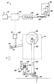
Figure 1 is a schematic depicting the aerator engine control device according to the
preferred embodiment of the present invention.
Figure 2 is a schematic electrical diagram showing the electrical circuit operatively
interconnecting the control lever, electrical system, solenoid, governor and linear actuators
according to the present invention.
DETAILED DESCRIPTION OF THE PREFERRED EMBODIMENT
Referring now to Figure 1, there is shown the aerator control mechanism 10
according to the preferred embodiment of the present invention. An electronic control

CA 022229~3 1997-12-18


switch or position control mechanism 12 is positioned in an operator station and is
engagable by an operator to shift the aerator mechanism 14 between a raised transport
position and a lowered operating position. The aerator mechanism 14 is coupled with the
frame 16 of a vehicle for pivoting about a transverse axis 18 as it shifts between the raised
and lowered positions. As the lever 12 is engaged by the operator an electronic system 20
coupled with the lever 12 actuates an electric linear actuator mechanism 22. The linear
actuator 22 is coupled with the aerator mechanism 14 and, together with the electrical
system 20 and control switch 12 serves as a position control mechanism for shifting the
aerator mechanism 14 between its raised and lowered positions.
The present invention also provides a power source control means. The power
source control means includes a solenoid 24 operatively coupled with the electrical system
20 and which is energized when the linear actuators 22 are shifting the aerator mechanism
14 between positions. When actuated, the solenoid 24 causes a plunger 26 to shift to the
left from its position shown in Figure 1. Shifting of the plunger 26 to the left applies a force
15 to a spring 28 which in turn pulls a governor arm 30. The governor arm 30 is coupled with a
governor shaft 32 of an engine governor 34. The governor 34 is operatively coupled with
the power source or engine 36 for preventing the engine 36 from operating at undesirably
high R.P.M.'s. As the arm 30 shifts to the left from its position shown in Figure 1, the
governor sha~ 32 will pivot therewith, causing the governor 34 to slow the engine 36. The
20 solenoid 24, plunger 26, spring 28, arm 30 and governor 34 thereby serve as a power
source control means which automatically slows the vehicle power source 36 when the
aerator mechanism 14 shifts between its transport and operating positions.
The aerator mechanism 14 shown in Figure 1 includes a drive wheel 38 driven by the
engine 36 and a ram link 40 having an upper end portion 42 pivotally coupled with the drive
25 wheel 38. A ground engaging tine 44 is fixed to the lower end portion 46 of ram link 40. A
resilient restraint device 48 is provided which generally allows the tine 44 and lower end
portion 46 of the ram link 40 to shift slightly as the tine 44 encounters forces applied by the
turf during operation. The resilient restraint 48 is intended to allow the tine 44 to create a
relatively neat opening in the turf during aerating operations without causing much damage
30 to the ground surface. The resilient restraint 48 includes a cylindrical rubber mount 50 fixed
with the vehicle frame 16. A rectangular tube section 52 is fixed with the mount 50. A bolt
54 which extends between a pair of laterally spaced plates 56 defines a pivot axis of a first
link member 58 rigidly coupled with the rectangular tube section 52. The first link member

CA 022229~3 1997-12-18


58 is pivotally coupled with a second link member 60 which is pinned to the lower end
portion 46 of the ram link 40 n~ar the tine 44. As the tine 44 encounters forces as it is
driven into the ground the rubber mount 50 will flex to allow some movement of the tine 44
in response to the force. Also, the rubber mount 50 will act as a biasing mechanism for
5 returning the tine 44 to its proper position after the tine 44 has been pulled out of the ground
by rotation of the drive wheel 38. The rubber mount 50 therefore properly positions the tine
44 for being forced into the ground again at the appropriate angle.
Slowing of the engine 36 as the aerator mechanism 14 shifts between its raised and
lowered positions has been seen to reduce or eliminate the damage done to the turf by the
10 tines 44 during this transitional period. Slowing of the engine 36 reduces the engine
R.P.M.s from approximately 3300 to approximately 2400. Since the drive wheel 38 is
driven by the engine 36, the drive wheel 38 will be correspondingly slowed as the engine
R.P.M. drops. The drive wheel R.P.M.s will slow from approximately 600 to approximately
450. In this sense, the present invention serves as a tine speed control mechanism which
15 slows the speed of the tines 44 into and out of the ground when the aerator mechanism 14
shifts between raised and lowered positions. Slowing of the engine 36 also slows the
vehicle's ground speed. In this sense, the present invention serves as a vehicle speed
control mechanism which slows the ground speed of the vehicle when the aerator
mechanism 14 shifts between raised and lowered positions. The present invention is
20 particularly useful with aerators having resilient restraining mechanisms which allow limited
movement of the tines 44. However, the present invention could also be useful ineliminating damage to turf during transitional periods when used with aerators having
linkages that positively define the position of the tines 44 during aerating operations.
Referring now to Figure 2, there is shown a schematic electrical diagram of a circuit
25 which operatively connects the control switch or jog switch 12, the electrical system 20,
solenoid 24 and linear actuators 22. As the operator engages the control switch lever 12 a
circuit is completed which directs current to the solenoid 24 and linear actuators 22 arranged
in parallel relation. Lift limiters (not shown) such as conventional reed switches are mounted
with the aerator mechanism 14 and sense the movement of the aerator mechanism 1430 between the raised and lowered positions. The lift limiters are also electrically coupled with
the circuit shown in Figure 2 and serve to stop the linear actuators 22 as the aerator
mechanism 14 reaches its extreme raised or lowered positions.
The preferred embodiment of the present invention provides a solenoid 24

CA 022229~3 1997-12-18


operatively coupled with an electrical system 20. However, a mechanical device could also
be employed within the spirit Qf the pi;esent invention. Furthermore, if an electrical governor
is utilized, the control of the electronic governor could be provided electrically by an electric
circuit.
The preferred embodiment of the present invention provides an electric linear
actuator 22 with an electric motor which applies a force to pivot the aerator mechanism 14
between its raised transport position and its lowered operating position. Other lift
mechanisms, such as hydraulic lift cylinders, could also be provided within the spirit of the
present invention.

Representative Drawing
A single figure which represents the drawing illustrating the invention.
Administrative Status

For a clearer understanding of the status of the application/patent presented on this page, the site Disclaimer , as well as the definitions for Patent , Administrative Status , Maintenance Fee  and Payment History  should be consulted.

Administrative Status

Title Date
Forecasted Issue Date 2001-08-07
(22) Filed 1997-12-18
Examination Requested 1997-12-18
(41) Open to Public Inspection 1998-08-05
(45) Issued 2001-08-07
Deemed Expired 2006-12-18

Abandonment History

There is no abandonment history.

Payment History

Fee Type Anniversary Year Due Date Amount Paid Paid Date
Request for Examination $400.00 1997-12-18
Registration of a document - section 124 $100.00 1997-12-18
Application Fee $300.00 1997-12-18
Maintenance Fee - Application - New Act 2 1999-12-20 $100.00 1999-12-17
Maintenance Fee - Application - New Act 3 2000-12-18 $100.00 2000-12-15
Final Fee $300.00 2001-04-30
Maintenance Fee - Patent - New Act 4 2001-12-18 $100.00 2001-12-17
Maintenance Fee - Patent - New Act 5 2002-12-18 $150.00 2002-12-17
Maintenance Fee - Patent - New Act 6 2003-12-18 $150.00 2003-12-17
Maintenance Fee - Patent - New Act 7 2004-12-20 $200.00 2004-12-02
Owners on Record

Note: Records showing the ownership history in alphabetical order.

Current Owners on Record
DEERE & COMPANY
Past Owners on Record
LAMB, MARK EDWARD
SIMON, MERLIN EMMET
TEIGA, MICHAEL TIMOTHY
Past Owners that do not appear in the "Owners on Record" listing will appear in other documentation within the application.
Documents

To view selected files, please enter reCAPTCHA code :


To view images, click a link in the Document Description column. To download the documents, select one or more checkboxes in the first column and then click the "Download Selected in PDF format (Zip Archive)" or the "Download Selected as Single PDF" button.

List of published and non-published patent-specific documents on the CPD .

If you have any difficulty accessing content, you can call the Client Service Centre at 1-866-997-1936 or send them an e-mail at CIPO Client Service Centre.


Document
Description 
Date
(yyyy-mm-dd) 
Number of pages   Size of Image (KB) 
Representative Drawing 2001-07-27 1 6
Claims 2000-11-14 3 167
Cover Page 1998-08-05 1 42
Abstract 1997-12-18 1 13
Description 1997-12-18 5 246
Claims 1997-12-18 3 115
Drawings 1997-12-18 2 23
Cover Page 2001-07-27 1 34
Representative Drawing 1998-08-05 1 6
Prosecution-Amendment 2000-09-28 2 2
Prosecution-Amendment 2000-11-14 5 221
Assignment 1997-12-18 7 204
Correspondence 2001-04-30 1 25