Note: Descriptions are shown in the official language in which they were submitted.
CA 02223l73 l997-l2-02
W O 96/40537 PCT~US96/08417
ADJUSTABLE ARM REST ASSEMBLY
BACKGROI~ND OF THE INVENl~ON
The present invention relates to the field of arm rests for use on chairs.
More particularly, the invention relates to the field of arm rests which are adjustable to
various positions and heights to provide a more colllfolL~ble chair for a user.
Chairs, particularly office chairs, are often de~ nP~ with the arm rests
secured in a fLxed position based on the inten~e~ use of the chair and the average size of
the expected users. However, in an office e~lvilu~ nt~ people of dirrele,~t sizes may
spend many hours in the same size chair. Therefore, it is desirable to have arm rests that
are adjustable to match the specific anatc""y of a given user. A chair, in particular the
arm rests, should be co",ro-Lable for people of widely varying sizes and shapes.Simil~rly, an arm rest should be adjustable depen-ling on the varied activities of the user
of the chair. For eY~mrlP, a user may desire to have an arm rest at a first height when
working with a pen and paper on a desk, but desire a second height when working with a
colll~ulel. In ~ ition, arm rests should also be angularly adjustable in order to
accommodate the varied activities ~ led with use of the chair. A user may desire the
arm rests in a first angular position when typing or working with a pen and paper. The
user, however, may desire a second angular position when working with a mouse for a
col,,~ulel.
Some adjustable arm rests have been rli~closecl in the prior art. For
eY~mple-, in U.S. Patent No. 4,951,995 issued to Teppo et al., a complex àrm height
adj~ -Pnt mPrh~ni~m for a chair is ~ clos~cl A vertical motion tr~n~l~ti-~n m~rh~ni~m
inLel~onnects two laterally spaced arm rests. A cable assembly together with a rotatable
gear t~n~l~te movement from a first arm into a colle~ponding movement in the second
arm thereby providing for the synchloni~d movement of the arm rest assemblies. U.S.
Patent No. 4,884,846 issued to Tobler, ~ closes arm rests with limited height adjllstm~ont
capabilities. The arm rest is adjusted through the rotation of a carrier t-lemPnt on the arm
rest ~u~ . The support elem~nt is a two part bolt construction with right-hand and left-
hand threads coupled together by the carrier ~ m~nt
CA 02223173 1997-12-02
W 096/40537 PCTAJS96/08417
While adjustable arm rests have been previously rli.er,lo~ee~, there still exists
a need for adjustable arm rests that provide reliable operation at a reduced m~mlf~t~tllring
cost.
SUMMARY OF THE lNVEN~ON
Briefly stated, the present invention is directed to an adjustable arm rest
assembly for use on a chair inrlu~lin~ a support mPmhPr, an arm rest mPmbPr, a locking
elemPnt and an adj~letmP-nt mPmhPr. According to a first aspect of the invention, the
support mPmbPr is ~tt~rhPi to the chair and extends subst~nti~lly upward thelcr ulll. The
arm rest member extends subst~nti~lly co~xi~lly with the support mPmhe.r. The locking
P~lempnt is ~tt~ehp~tl to one of the support member and the arm rest member. A projecting
surface extends from an end portion of the locking P-lemPnt and inch~des a first mating
PlemPnt The adjlletmP-nt member is ~tt~t~hP~ to the other of the support mPmher and the
arm rest member. The adjuetmP-nt member and the locking element are movable withrespect to one another. A plurality of vertically spaced flanges form a plurality of
l!i recesses within the adjuetmP-nt member. Each recess is sized to receive the projecting
portion of the locking ele-mPnt and has a second mating elemPnt co~ ding to the first
mating elpmpnt The arm rest member is angularly movable when the first and second
mating elements are ~licpng~ged~ The arm rest member is also angularly and vertically
movable when the first and second mating elemçnte are ~icçng~ged and the projecting
portion of the locking PlPmPnt is ~lic-p-ng~ged from the recess of the adjlletm~nt member.
According to another aspect of the invention, the locking çlçmPnt is
Zltt~( hP~ to the support member and the adjnetm~P-nt mPmher is ~tt~hP~l to the arm rest
member.
According to a further aspect of the invention, the first mating el~PmPnt
compriePs a plurality of vertically e~tPn~ling teeth and the second mating element
comprises a pin-shaped sllrf~e-
The adjustable arm rest assembly of the present invention has three basic
modes of operation: 1) a locked position, 2) an angularly movable position, and 3) an
angularly and vertically movable position. In the locked position, the projecting surface
of the locking PlPmPnt is engaged within a recess of the adj-letmPnt member and the first
and second mating elPmPnte are engaged. In the angularly movable position, the
projecting surface of the locking PlPmPnt is engaged within the recess of adjustmPnt
CA 02223173 1997-12-02
W O 96/40537 PCTAJS96/08417
mPmbPr. However, the first and second mating el~PmPnte are rliePng~ged so as to allow
for angular movement of the arm rest mPmbpr~ In the angularly and vertically movable
~ position, the projecting surface of the locking elemPnt is ~1iepng~ged from the recess of
the adjiletmP-nt mPmhPr and the first and second mating elomPnte are also diepng~ged. In
this poeiti-~n~ the arm rest m~mber is angularly and vertically movable to a position
sPIectP~ by a user.
The present invention will be best understood with reference to the det~il~
description below read in conjunction with the accompanying drawings.
BRIEF DESCRIPIION OF T~IE DRAWINGS
FIGURE lis an exploded view of a plefe,led embodiment of the
adjustable arm rest assembly of the present invention;
FIGURE 2is a yc;~ e view of a ~lef~ d embodiment of the
adjustable arm rest member of the present invention;
FIGURE 3is a front view of a pler~llc;d embodiment of the adjustable arm
1~ ~est ~.~l.el of the present invention without the actuation elemPnt;
FIGURE 4 is a top view of the pl~;fell~d embodiment of the present
invention with the arm rest member in a locked position;
FIGURE 5 is a top view of the p~ef~lled embodiment of the present
invention with the arm rest mPmher in a partially unlocke~ position or an angularly
adjustable position;
FIGURE 6is a top view of the pler~lled embodiment of the present
invention with the arm rest member shown in the unlocke~ position so as to be angularly
and vertically adjustable;
FIGURE 7is a ~ ~ e view of the pawl of the pr~r~ d embodiment
2~ of the present invention; and
FIGURE 8is a perspective view of the adj-lstme-nt member of the ~lt;relred
embodiment of the present invention.
CA 02223l73 l997-l2-02
WO 96/40537 PCTAUS96/08417
DETAl~,F~ DESCRIPIION OF THE ~REFFRRF~n EMBODIME~TS
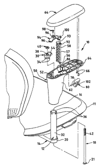
~?P-fe~ring to the dl~Lwi~gs, Fig. 1 shows an adjustable arm rest ~ mhly 10
for use on a chair 11 in accol~lce with a plt;r~ d embodiment of the present invention.
The ~emhly 10 inrlll(les a support mPmher 12 or tube that is fixed to a chair 11 beneath
the seat thereof. A mounting el~m~nt 14 extends oulw~d from beneath the seat of the
chair 11 with the support mPmhPr 12 PYtPn-lin~ vertically upward lh~l~erlum. The support
mPmber 12 has an int~orn~l p~ geway 16 so that the central portion of the rod 18 can
pass tht;l~Lhlough. An a~;llule 20 in the mountin~ PlPmPnt 14 receives the button head
21 of the rod 18.
A locking elPmPnt or pawl 30 is secured within the top portion 32 of the
support member 12. The pawl 30 has four flanges 34 (two shown) that extend at 90degree angles and mate with colles~llding apertures 36 within the top portion 32 of the
support mçmhPr 12. The pawl 30 has a centrally po~itionPll a~lLule 38 çYtPnrling there-
Ll.rw~gh, A f~tPnin~ mPrll~ni~m 40 such as a hex nut is mounted therein so as to engage
IS the upper threaded portion 42 of the rod 18. As a result, the pawl 30 is secured in a
fixed location to the support member 12 and the chair 11. As best seen in Fig, 7, the
pawl 30 has an oulw~dly projecting portion 44. This projecting portion 44 has a
plurality of subst~nti~lly vertically PYtçn~ling teeth 46 on the end thereof. According to
the ~refe.led emboAim~nt, the pawl 30 inrludes three teeth 46.
In a pl~re.led embo liment~ the mounting Plp-mpnt 14 has a steel core with a
plastic covering. The support mPmhPr 12 may be m~nuf~ctllred from steel using a cold
roll process and the pawl 30 from a plastic m~tPri~l such as acetal.
The arm rest memher 50 is slidably mounted on the support member 12.
The arm rest member 50 has an intPrn~l pas~g~w~y S2 or cavity that is sized to receive
the support member 12. The arm rest mPmber 50 and the support member 12 extend
subst~nti~lly co~Yi~lly with the arm rest mPmhPr 50 adjustable in a telescoping manner
relative to the support mPmher 12. The arm rest member 50 has a centrally located and
jnt~Prn~l boss that receives a dow--w~dly PYtçn-ling hub 56 from the bottom 57 of the
adju~tmPnt member 58. As shown in Fig. 3, a slot 60 extends ho,izont~lly in the upper
portion 62 of the arm rest member 50. A top surface 64 of the arm rest member 50lCCeiVeS an arm pad 64 that ~u~po,l~ the arm of a user, A f~tçning mech~ni~m such as
screws 66 serve to secure the arm pad 64 to the arm rest member 50.
CA 02223l73 l997-l2-02
W O 96/40537 PCTAUS96/08417
As shown in Figs. 1 and 8, the adj~stmPnt member 58 has a plurality of
vertically aligned rP~s~s 70 formed by a plurality of holiLlJ-,L~lly eYten-ling flanges 71.
Each recess 70 is sized so as to receive the uuLw~dly projecting portion 44 of the
pawl 30. In the plGr~llGd embo~1imP-nt, the adj-lctmPnt member 58 contains seveniecesses 70. Within each recess 70, a pin-shaped surface 72 is cPntr~lly located along the
curved back wall 74 thereof. The pin-shaped surface 72 is sized to mate with one of the
teeth 46 on the pawl 30. In a ~lGf~l~ed embo-limPnt, the adj--ctmlont mPmhPr 50 has a
height of applo~dil-laLely S inches with each recess 70 having a height of app~ ely
3/8 inch. The adjnctmp-rlt mPmhPr 50 preferably has a length of ~ i,l,aLely 11/B inch
and a depth of a~ro~im~tP-ly Ys inch. A square steel shaft 78 is mounted to the
adjuctmPnt mPmhPr 58 on the opposite side of the lecesses 70 for use with the ~ct~ti~n
member 80. The shaft 78 passes l~ ugh the slot 60 in the upper portion 62 of the arm
rest member 50. Slightly above the shaft 78, a spring Png~gPmPnt surface 84 projects
ouLw~ud a short ~ict~nre from the adj~ctmPnt mPmber. The spring 86 is connP~tP~l to the
lS engagement surface 84 on the adj--ctmPnt mPmbPr 58 and eYtPnrlc to the clip 88 on the top
surface 64 of the arm rest member 50. The spring 86 acts to bias the adj~ -n~
member 58 into engagement with the pawl 30. Preferably, the adj~stmP-nt member 58
and the arrn rest member 50 are manufactured using an injection m~k1ing process using
glass-filled nylon as produced by Allied Signal under Part No. 8233G. Also, in aIJlGfGllGd embo limP-nt the ~rtl~tic n elPmPnt 80 is formed from polyplol,ylene.An upper hub 92, collG~L~nding to the lower hub 56, extends upward from
the top surface 93 of the adj~ctmPnt mPml~er 58. The upper hub 92 is movably cnnl-P~Ied
to the clip 94 that is mounted to the top surface 64 of the arm rest member 50. The
upper and lower hubs 92 and 56 define a pivot axis about which the adjustmP-nt
member 58 pivots when the ~r.t--~ticn mpmher 80 is moved by a user. More spe~ific~lly,
the adjllctmp-nt member 58 is pivotable about the axis defined by the upper and lower
hubs 92 and 56. In a prefelled embodiment, the clip 94 is m~mlf~rtllred from steel.
The clip 94 has three ~elLules 96 located along the outer periphery
thereof. The apertures 96 receive f~ctening elemPnt.c such as the screw 98 that pass
~ 30 LhGiGLhl~ugh. In this manner, the clip 94 is secured to the top surface 64 of the arm rest
member 50. The larger a~lLulG 100 receives the upper hub 92 of the adjnctmP-nt
I CA 02223l73 l997-l2-02
WO 96/40537 PCTAUS96/08417
member 58. Accordingly, the clip 94 and the boss 53 serve to secure the adjustment
memher 54 to the arm rest mPmh~r 50.
The ~tll~tifJn memh~r80is movably connect~ to the outer surface of the
arm rest m.omher S0. The shaft 78iS mounted to a rear portion of the ~ tll~tion
mPmhl~r 80 in a rh~nn-ol 102 so as to in~l~olmect the ~rtll?,tion member S0 and the
adjl-~tm~-nt mP.mhPr 58. The shaft 78 passes through and is movable along the length of
the slot 60. As a result, the ~-tll~tion member 80 is also movable in a hf..;,,nnl;.l plane
along the length of the slot 60.
It should be recognizRd that the plc;r~l~d embodiment of the present
invention shown in the Figures could be mf~ifi~l by those of ordin~y skill in the art so
as to still pr~fice the present invention. For eY~mple, the pl~relled embo~im~o-nt could
be mo lifi~d so as to change the relative inter~nnection of the locking el~-m.o-nt and the
adjllctm~-nt member with respect to the support m~mh-er and the arm rest memb~r. More
spe~ific~lly, the locking element could be movably ~tt~h~ to the arm rest member and
thE~ 7,7Ct'"~ -h~- fixedly ~tt~ch~ to the support member. The locking elemPnt
~d t~en be n~ved into and out engagement with the adjn~tmf-nt member in order toprovide the same relative modes of operation as will be described-below. According to
another modifif~tif n, the adj~l~tml-nt member could slidably engage the locking ~ m. nt
rather than pivotably. According to yet a further ma~ifir~tion, the mating teeth of the
pawl and the pin-shaped surface of the recess could be replaced with a detent and
plurality of lc;c~ ses. Accordingly, it should be l~cognized that the ~l~r~ d embodiment
of the Appli~ntc' invention shown in the Figures could be modified in a wide varie~ of
ways.
Figs. 4-6 best illllstr~te the actual operation of the arm rest assembly 10.
2~ In the locked position, as shown in Fig. 4, the spring 86 biases the adjuctmPnt member 58
into engagement with the pawl 30 so as to secure the arm rest member 50 in a fixed
position. More particularly, the projecting portion 44 of the pawl 30 is captured within a
recess 70 and one of the tReth 46 on the end of the pawl 30 is engaged by the pin-shaped
surface 72 on the back wall 74 of the recess 70. In this position, the arm rest member 50
is locked into position with the support mPmbçr 12.
In order to adjust the angular position of the arm rest member 50 (but not
the vertical position), a user would slide the actuation member 80 a~,.~ tely 10~
CA 02223173 1997-12-02
W 0 96/40537 PCT~US96/08417
along the outer sur~ce of the upper portion 62 of the arm rest mP.mhPr 50. The user
thereby overcomes~e force of the spring 86 that biases the adj--ctmPnt mPmher 56 and
the ~t-~tinn pl~mPnt 80 into the locked position. As a result of this m~v~ ent, the
adj~-ctmP-nt mPmh~r 58 pivots out a short ~lict~nce from engagement with the pawl 30.
More ~rel~.ifir~lly~ the teeth 46 of the pawl 30 are ~li.cPng~ged from the pin-shaped
surface 72 on the back wall 74 of the recess 70. However, the alju~ ..Pnt member 58
has not pivot~d so far as to completPly tli~ng~ge the projecting portion 44 from the
recess 70. Rather, the projecting portion 44 still re..lains cap~ur~d within the selPcte~
recess 70. In this position, as shown in Fig. 5, the arm rest mPmbP.r 50 may be rotated
in order to adjust the angular position of the arm rest member 50 relative to the support
member 12. The arm rest mP.mbP.r 50 is not vertically adjustable in this position.
After rot~ting the arm rest member 50 to the new angular position, a user
releases the actuation elçmPnt 80 in order to lock the arm rest member 50 into the new
angular position. The adj~ctmPnt member 58 pivots back into complete engagement as
efore. EJccept, in ~is new angular position, a dirrer~ilt tooth 46 on the end of the
~aw1 30 w~ll now be engaged by the pin-shaped surface 72 of the recess 70. In this
manner, the arm rest member 50 is now fixed in a new angular position.
In order to adjust the height or vertical position of arm rest member 50
relative to the support member 12, the user again slides the ~ct~tion member 80. This
time, however, the user must slide the ~-t~-~tic n elemPnt 80 at least 20~ or until the
shaft 78 reaches the o~J~osile end of the slot 60 so as to prevent further movement. By
moving the ~ctn~ti~n member 80 in this manner, the adj~ctmP-nt member 58 is pivoted
co",~ ly out from engagement with the pawl 30. In other words, the ent,ire projecting
portion 44 incl~l-ling the teeth 46 are completely ~ png~ged from the recess 70. In this
position, as shown in Fig. 6, the arm rest member 50 is movable both vertically and
angularly. The arm rest member 50 may then be moved upward, dowllw~-l or angularly
as selected by the user.
Once the user has SP-lP~tPA a new vertical position and angular position (if
desired), the actuation P.lPmPnt 80 is released so as return to the locked position. The
~ 30 adj--ctmPnt member 58 pivots back into engagement with the pawl 30. The projecting
portion 44 of the pawl 30 is now captured within a new recess 70 on the adjustment
member 58 with a tooth 46 on the end of the pawl 30 eng~ging the pin-shaped surface 72
CA 02223173 1997-12-02
W 096/40537 PCTrUS96/08417
in the recess 70. In the plc~r~ d embodiment, the adjustable arm rest assembly 10 has a
4-inch range of adj~ e,tmrnt
The embodiment desrrihe(1 is illlletr~tive and not restActive. The scope of
the invention is in~1ir~t~ by the claims rather than by the Çol~oillg descAption. For
eY~mple, as deecrihe~l above, the relative poeitioning of the adj.. el.. ~.-t member and the
pawl with respect to the support m~,mhPr and the arm rest m~-mh~-,r could be inl~l.,hallged
without departing from the spiAt of this invention. In ~ ition, the number of teeth in the
pawl or the specific m~t~,ri~l,c used to m~nllf~r,tllre the ~olemt~nte of the pre_ent invention
could also be changed. The invention therefore may be embodied in other specific forms
without departing from the spiAt of the invention. Accordingly, all ch~ng-o.s which come
within the scope of the claims are intentle~l to be embraced therein.