Note: Claims are shown in the official language in which they were submitted.
7
THE EMBODIMENTS OF THE INVENTION IN WHICH AN EXCLUSIVE PROPERTY OR
PRIVILEGE IS CLAIMED ARE DEFINED AS FOLLOWS:
1. An eyeglass device comprising:
a primary spectacle frame for supporting primary lenses therein, said primary
spectacle
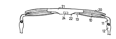
frame including a middle bridge portion,
a first magnetic member secured in said middle bridge portion of said primary
spectacle
frame,
an auxiliary spectacle frame for supporting auxiliary lenses therein, said
auxiliary
spectacle frame including a middle bridge portion having a projection extended
therefrom for
extending over and for engaging with said middle bridge portion of said
primary spectacle frame,
and
a second magnetic member secured to said projection of said auxiliary
spectacle frame for
engaging with said first magnetic member of said primary spectacle frame and
for allowing said
auxiliary spectacle frame to be attached to said primary spectacle frame with
only one hand by a
user.
2. An eyeglass device comprising:
a primary spectacle frame for supporting primary lenses therein, said primary
spectacle
frame including a middle bridge portion,
a first connector member secured in said middle bridge portion of said primary
spectacle
frame,
an auxiliary spectacle frame for supporting auxiliary lenses therein, said
auxiliary
spectacle frame including a middle bridge portion having a projection extended
therefrom for
extending over and for engaging with said middle bridge portion of said
primary spectacle frame,
a second connector member secured to said projection of said auxiliary
spectacle frame
for engaging with said first connector member of said primary spectacle frame,
and
8
magnetic means operatively associated with the first and second connector
members
whereby they are connectable to each other magnetically for allowing said
auxiliary spectacle
frame to be attached to said primary spectacle frame with only one hand by a
user.
3. The eyeglass device as claimed in claim 2, with the first connector member
being a
magnet, the second connector member being a magnetizable substance.
4. The eyeglass device as claimed in claim 2, with the second connector member
being a
magnet, the first connector member being a magnetizable substance.
5. An eyeglass device comprising:
a first frame including
two retaining mechanisms for supporting a pair of lenses, and defining a
frontal plane,
a bridge connecting the two retaining mechanisms and holding the two retaining
mechanisms
together, and
a magnetic member at the bridge for magnetically coupling to another magnetic
member at the
bridge of a second frame;
such that, when coupled, the two frames are attached together and the coupling
occurs at a
coupling surface at an angle with respect to the frontal plane of between
about 45 and 90 degrees.
6. An eyeglass device as recited in claim 5 wherein the coupling occurs at the
coupling
surface on the second frame that is substantially perpendicular to the frontal
plane.
7. An eyeglass device as recited in claim 5 wherein the magnetic member at the
bridge of
the first frame is a permanent magnet.
8. An eyeglass device as recited in claim 5 wherein the magnetic member at the
bridge of
the first frame is in a cavity to receive the second frame's magnetic member,
which protrudes
from the member, with at least a part of the protrusion fitting into the
cavity.
9. An eyeglass device as recited in claim 5 wherein the magnetic member at the
bridge of
the first frame comprises two separate parts, with each part being adjacent to
one of the retaining
mechanisms.
9
10. An eyeglass device as recited in claim 5 wherein the bridge of the second
frame further
includes a protrusion for engaging with the bridge of the first frame so as to
further secure the
attachment of the two frames when coupled.
11. An eyeglass device as recited in claim 10 wherein:
the first frame is an auxiliary frame to be coupled to the second frame, which
is a primary frame;
and
the magnetic member at the auxiliary frame is a permanent magnet to be coupled
to the second
frame's magnetic member, which is a magnetizable member.
12. An eyeglass device as recited in claim 5 wherein:
the bridge of the first frame further includes a U-shaped structure having two
arms; and
the magnetic member at the first frame is disposed at least on one of the
arms;
such that magnetic coupling occurs when the bridge of the second frame is
sandwiched between
the arms of the U-shaped structure.
13. An eyeglass device as recited in claim 5 wherein the first frame is an
auxiliary frame to
receive the second frame, which is a primary frame.
14. An eyeglass device as recited in claim 13 wherein the magnetic member at
the bridge of
the auxiliary frame comprises two separate parts, with each part being
adjacent to one of the
retaining mechanisms.
15. An eyeglass device as recited in claim 13 wherein the auxiliary frame
further includes a
projection that extends from the bridge of the frame to further secure the
attachment of the
auxiliary frame to the primary frame.
16. An eyeglass device as recited in claim 15 wherein the projection includes
two extensions,
each extending laterally from one end of the bridge;
such that when the auxiliary frame is attached to the primary frame, a portion
of each retaining
mechanism of the primary frame is disposed between a portion of a retaining
mechanism of the
auxiliary frame and a portion of one lateral extension.
17. An eyeglass device as recited in claim 15 wherein the projection includes
a protrusion,
extending vertically from the bridge;
such that when the auxiliary frame is attached to the primary frame, the
bridge of the primary
frame is disposed between frontal plane and at least a portion of the
protrusion.
18. An eyeglass device as recited in claim 17 wherein the width of the bridge
of the auxiliary
frame is wider than the width of the bridge of the primary frame so that when
the auxiliary frame
is attached to the primary frame, there can be a gap between the protrusion
and the bridge of the
primary frame.
19. An eyeglass device comprising:
an auxiliary frame including
two retaining mechanisms for supporting a pair of lenses, and defining a
frontal plane,
a bridge connecting the two retaining mechanisms and holding them together,
and
a magnetic member at the bridge; and
a primary frame including
two retaining mechanisms for supporting a pair of lenses,
a bridge connecting the two retaining mechanisms and holding them together,
and
a magnetic member at the bridge for magnetically coupling to the magnetic
member at the bridge
of the auxiliary frame;
such that, when coupled, the two frames are attached together and the coupling
occurs at a
coupling surface at an angle with respect to the frontal plane of between
about 45 and 90 degrees.
20. An eyeglass device as recited in claim 19 wherein the coupling occurs at
the coupling
surface on the primary frame that is substantially perpendicular to the
frontal plane.
21. An eyeglass device as recited in claim 19 wherein the magnetic member at
the bridge of
the auxiliary frame is a permanent magnet.
22. An eyeglass device as recited in claim 19 wherein each magnetic member at
each bridge
comprises two separate parts, with each part being adjacent to one of the
retaining mechanisms
of the corresponding frame.
23. An eyeglass device as recited in claim 19 wherein the auxiliary frame
further includes a
projection that extends from the bridge of the frame to further secure the
attachment of the
auxiliary frame to the primary frame.
24. An eyeglass device as recited in claim 21 wherein:
the bridge of the primary frame includes a protrusion; and
11
the bridge of the auxiliary frame includes a cavity to receive the protrusion
at the bridge of the
primary frame so as to further secure the attachment of the two frames when
coupled.
25. An eyeglass device as recited in claim 24 wherein:
the bridge of the auxiliary frame further includes a projection that extends
from the bridge of the
frame to further secure the attachment of the auxiliary frame to the primary
frame; and
the projection includes a protrusion, extending vertically from the bridge;
such that when the auxiliary frame is attached to the primary frame, the
bridge of the primary
frame is disposed between frontal plane and at least a portion of the
protrusion.
26. An eyeglass device comprising:
a primary frame including
two retaining mechanisms for supporting a pair of lenses, and defining a
frontal plane,
a bridge connecting the two retaining mechanisms, and holding them together,
and
a first magnetic member at the bridge for magnetically coupling to a second
magnetic member at
the bridge of an auxiliary frame;
such that, when coupled, the two frames are attached together and the coupling
occurs at a
coupling surface on the primary frame that is substantially perpendicular to
the frontal plane.
27. An eyeglass device as recited in claim 26 wherein the magnetic member at
the bridge of
the primary frame is a magnetizable member.
28. An eyeglass device as recited in claim 26 wherein each magnetic member at
each bridge
comprises two separate parts, with each part being adjacent to one of the
retaining mechanisms
of the corresponding frame.
29. An eyeglass device as recited in claim 26 wherein the primary frame can be
attached to
the auxiliary frame, which further includes a projection that extends from the
bridge of the
auxiliary frame to further secure the attachment of the auxiliary frame to the
primary frame.
30. An eyeglass device as recited in claim 26 wherein the bridge of the
primary frame
includes a cavity that can receive a protrusion at the bridge of the auxiliary
frame so as to further
secure the attachment of the two frames when coupled.
31. An eyeglass device as recited in claim 30 wherein the primary frame can be
attached to
the auxiliary frame, which further includes a projection with a vertical
extension that extends
12
from the bridge of the auxiliary frame to further secure the attachment of the
auxiliary frame to
the primary frame;
such that when the primary frame is attached to the auxiliary frame, the
bridge of the primary
frame is disposed between frontal plane and at least a portion of the
extension.
32. An eyeglass device as recited in claim 6 wherein the two frames are
coupled, the
orientation of the magnetic member of the first frame is substantially the
same as the orientation
of the magnetic member of the second frame at the coupling surface.
33. An eyeglass device as recited in claim 6 wherein:
the first frame includes a first-frame coupling surface; and
the magnetic member of the first frame slightly protrudes from the first-frame
coupling surface to
enhance magnetic coupling when the two frames are coupled.
34. An eyeglass device as recited in claim 6 wherein at least one magnetic
member slightly
recedes from the coupling surface so that the two magnetic members are
magnetically, but not
mechanically, coupled when the two frames are coupled together.
35. An eyeglass device as recited in claim 6 wherein:
the surface of each magnetic member that is for magnetic coupling to another
magnetic member
is defined as a magnetic coupling surface; and
the magnetic coupling surface of each magnetic member has no bumps to enhance
coupling
between the two frames.