Language selection

Search

Patent 2223313 Summary

Third-party information liability

Some of the information on this Web page has been provided by external sources. The Government of Canada is not responsible for the accuracy, reliability or currency of the information supplied by external sources. Users wishing to rely upon this information should consult directly with the source of the information. Content provided by external sources is not subject to official languages, privacy and accessibility requirements.

Claims and Abstract availability

Any discrepancies in the text and image of the Claims and Abstract are due to differing posting times. Text of the Claims and Abstract are posted:

  • At the time the application is open to public inspection;
  • At the time of issue of the patent (grant).
(12) Patent Application: (11) CA 2223313
(54) English Title: SUCTION UNIT FOR HOODS, OVENS AND SIMILAR APPLIANCES HAVING A CASING WITH TWO OR MORE ADJACENT AND SPACED AUGERS
(54) French Title: UNITE D'ASPIRATION POUR HOTTES DE CUISINE, FOURS ET APPAREILS ELECTROMENAGERS SEMBLABLES MUNIS D'UNE ENVELOPPE AVEC DEUX COMPARTIMENTS OU PLUS CONTIGUS ET ESPACES
Status: Deemed Abandoned and Beyond the Period of Reinstatement - Pending Response to Notice of Disregarded Communication
Bibliographic Data
(51) International Patent Classification (IPC):
  • F04D 29/40 (2006.01)
  • B08B 15/02 (2006.01)
  • F04D 17/10 (2006.01)
  • F04D 29/42 (2006.01)
  • F04D 29/62 (2006.01)
  • F24C 15/20 (2006.01)
(72) Inventors :
  • BACCHIOCCHI, ALBERTO (Italy)
(73) Owners :
  • F.I.M.E.-FABBRICA ITALIANA MOTORI ELETTRICI S.R.L.
(71) Applicants :
  • F.I.M.E.-FABBRICA ITALIANA MOTORI ELETTRICI S.R.L. (Italy)
(74) Agent: GOWLING WLG (CANADA) LLP
(74) Associate agent:
(45) Issued:
(22) Filed Date: 1997-12-02
(41) Open to Public Inspection: 1998-06-06
Availability of licence: N/A
Dedicated to the Public: N/A
(25) Language of filing: English

Patent Cooperation Treaty (PCT): No

(30) Application Priority Data:
Application No. Country/Territory Date
U.M. MC96U000049 (Italy) 1996-12-06

Abstracts

English Abstract


This invention concerns a suction unit for hoods, ovens and similar appliances
consisting of a double auger casing in which the two augers are adjacent but
spaced so that two separate suction inlets may be realised on the same, one
on the external side and the other on internal side.


French Abstract

Unité d'aspiration pour hotte de cuisines, fours et appareils électroménagers semblables comportant une enveloppe à double compartiment dans laquelle les deux compartiments sont contigus mais espacés de façon que deux entrées d'aspiration séparées soient placées sur le même compartiment, une sur le côté extérieur et l'autre sur le côté intérieur.

Claims

Note: Claims are shown in the official language in which they were submitted.

-6-
CLAIM
1. A suction unit of the type consisting of an electric motor (1)
housed in a cylindrical cover (2) and crossed by a shaft having several fans (6)splined at its ends; each of said fans (6) operating inside an auger provided
with respective outflow outlet and forming an integral part of the casing (7)
which entirely houses the fan motor unit and characterised in that the series
of augers (8 or 80) are adjacent but spaced by a space (9 or 90) and
characterised by the fact that said augers (8 or 80) have two suction inlets, ofwhich one (8a) on the external side and the other (8b) on the internal side; it
being provided that each fan (6) has two series of blades (6a), one positioned
in the direction of the suction inlet (8a) on the external side of the respective
auger (8) and the other positioned in the direction of the suction inlet (8b) onthe internal side of the same auger (8).

Description

Note: Descriptions are shown in the official language in which they were submitted.


CA 02223313 1997-12-02
Suction Unit for Hoods, Ovens and Similar Appliances Having a Casing with
Two or More Adjacent and SPaced Augers
This design patent application concerns a suction unit for hoods, ovens and
similar appliances having two or more fans housed in respective adjacent and
5 spaced augers.
This invention concerns a powerful suction unit of the type having a single
electric motor driving several fans.
In the suction units of this type currently available on the market, the ends ofa shaft on which two fans are splined project from the sides of said motor;
10 each fan consisting of a disk supporting a series of blades having horizontal axis facing the side opposite the motor.
Currently suction units of this kind are provided with a special casing
consisting of two separate adjacent augers positioned close against each other;
it being provided that the motor driving both fans is flush mounted at the
15 centre of said casing.
Each side of said casing is provided with an opening (or suction inlet) through
which the external air is drawn into each auger by the respective fan.
Considering that the internal compartment of each auger is separated from the
internal compartment of the adjacent auger, it is evident that each auger uses
20 only one air suction inlet: namely the opening on the external side.
Moreover said positioning of the suction inlets is also the reason for which theblades of the two fans of conventional suction units are turned towards the
external side of the casing.
It should be remembered in passing that the outlet of each of these
25 conventional augers is provided with a hole through which the air previously
drawn through the side inlet is discharged.
The scope of this invention is to improve the performance and operating
method of said double auger suction units.
In particular this has been achieved by designing a special casing which can
30 house a motor and relevant pair of fans mounted at its sides, characterised by
the use of two adjacent but spaced augers so that a space is formed between
the same.

CA 02223313 1997-12-02
The decision to space the two augers also led to the creation of a second
suction inlet on each of the same.
This means that each of said new augers may use two separate suction inlets;
the first inlet, namely the traditional inlet, is realised in proximity of the external
5 side while the second inlet, namely the new inlet, is realised on the internal side, namely on the same side housing the motor.
In this respect it is evident that the internal sides of the two augers as well as
their relevant openings are placed - in the case of the casing according to the
invention - in an opposing position but spaced from the above space.
10 It should be noted that the presence of two suction inlets on each auger is
extremely important in terms of operation and performance of the double fan
suction unit.
It is evident that in the case of the unit according to the invention each augercasing thanks to its two suction inlets will have - at the same conditions
15 (power and motor r.p.m., auger dimensions etc.) - a significantly greater
suction capacity with respect to conventional units.
Moreover it should be noted that the major air flow which obviously occurs in
the new augers, with respect to that occurring in conventional augers having
a single suction inlet, permits the former to have the same suction capacity as
20 the second with the motor running at a lower speed and thus ensuring an
energy saving and lower noise level.
It should also be noted that the two side inlets on each auger has permitted theuse of special fans; in fact each of these fans is of the type consisting of a
centre disk having a series of respective perimeter fins on both sides.
25 It follows that each fan mounted on the new suction unit in question uses a
series of fins turned towards the external side of the respective auger and a
second identical series of fins turned toward the internal side of the same
auger.
Finally it should be noted that the presence of the above space between the
30 two augers does not alter the transverse dimensions of the casing, whose
outflow outlet may be fitted directly without the use of a manifold or pipe
fitting, to the pipe through which air is discharged to the exterior.

CA 02223313 1997-12-02
-4-
This characteristic of the unit according to the invention is particularly
important in that in this way it is perfectly interchangeable with conventional
suction units, with respect to which however it has a major flow, greater head
and better performance at the same absorbed power and vice versa.
5 Attention is also drawn to the fact that all the above advantages and features-
deriving from the idea to use two adjacent but spaced augers - increase as the
number of adjacent spaced augers increases.
For major clarity the description continues with reference to the enclosed
drawings which are intended for purposes of illustration and not in a limiting
10 sense and which illustrate two structurally different embodiments of the sameinvention, one consisting of two adjacent and spaced augers and the other
consisting of three adjacent and spaced augers.
Figures 1 and 2 refer to the first embodiment while figures 3 and 4 refers to
the second embodiment.
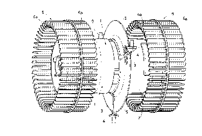
15 - figures 1 and 3 are two axonometric views of the fan-motor according to the invention in the above two structural embodiments;
- figures 2 and 4 are the cross-section of the casing housing the fan-motor
illustrated respectively in figures 1 and 3.
With reference to figure 1, the motor (1) of the suction unit in question is in
20 part housed in a cylindrical cover (2) provided externally with three radial arms
(3) placed at 120~ two of which are turned upward and one is turned
downwards, all terminating with respective pins having vertical axis (4) each
with enlarged end base (4a).
In the case of the embodiment according to the invention illustrated in figure
25 1, said radial arms (3) are incorporated in a disk (5) realised outside the
cylindrical cover (2).
Two fans (6) of the type consisting of a ring having a respective series of
blades (6a) on its two faces are splined at the ends of the through shaft of themotor (1) - namely on the right and on the left of the motor (1).
30 With reference to figure 2, the casing (7) consists of two adjacent augers (8)
spaced by a gap (9).
Both the sides of each auger (8) are provided with suction inlets (8a and 8b),
the first (8a) on the external side and the second (8b) on the internal side.

CA 02223313 1997-12-02
Figure 2 shows the arrows illustrating the flow of air drawn through both the
two external suction inlets (8a) and through the two suction inlets (8b).
The number (10) refers to two of the three bushings fitted in the space (9)
designed to house the pins (4) provided at the ends of the radial arms (3)
5 projecting from the cover (2) to ensure secure fixing of the fan-motor unit to the casing (7).
It is evident that the above disk (5) provided on the exterior of the cylindrical
cover (2) is positioned between the two opposing inlets (8b) provided in
proximity of the internal sides of each auger (8); said disk (5) has an accident10 prevention function, nameiy that of preventing the operator from inserting a
finger into said suction inlets.
A detailed description of figures 2 and 4 is not considered to be necessary in
that the only difference in the second structural embodiment of the invention
with respect to the first embodiment is the use of three spaced and adjacent
- 15 augers (80) separated by respective spaces (90).
In the second embodiment there are three fans (6) despite the fact that there
is only one motor (1).
In this regard it should be noted that the same numbers used in figures 1 and
3 were used in figures 2 and 4 to illustrate the corresponding structural
20 components in the first and second embodiments of the invention.

Representative Drawing
A single figure which represents the drawing illustrating the invention.
Administrative Status

2024-08-01:As part of the Next Generation Patents (NGP) transition, the Canadian Patents Database (CPD) now contains a more detailed Event History, which replicates the Event Log of our new back-office solution.

Please note that "Inactive:" events refers to events no longer in use in our new back-office solution.

For a clearer understanding of the status of the application/patent presented on this page, the site Disclaimer , as well as the definitions for Patent , Event History , Maintenance Fee  and Payment History  should be consulted.

Event History

Description Date
Inactive: IPC from MCD 2006-03-12
Time Limit for Reversal Expired 2001-12-03
Application Not Reinstated by Deadline 2001-12-03
Deemed Abandoned - Failure to Respond to Maintenance Fee Notice 2000-12-04
Application Published (Open to Public Inspection) 1998-06-06
Inactive: IPC assigned 1998-03-23
Inactive: First IPC assigned 1998-03-23
Inactive: IPC assigned 1998-03-23
Classification Modified 1998-03-23
Inactive: Filing certificate - No RFE (English) 1998-03-16
Application Received - Regular National 1998-02-26
Filing Requirements Determined Compliant 1998-02-26
Letter Sent 1998-02-26
Inactive: Filing certificate - No RFE (English) 1998-02-26

Abandonment History

Abandonment Date Reason Reinstatement Date
2000-12-04

Maintenance Fee

The last payment was received on 1999-10-18

Note : If the full payment has not been received on or before the date indicated, a further fee may be required which may be one of the following

  • the reinstatement fee;
  • the late payment fee; or
  • additional fee to reverse deemed expiry.

Please refer to the CIPO Patent Fees web page to see all current fee amounts.

Fee History

Fee Type Anniversary Year Due Date Paid Date
Registration of a document 1997-12-02
Application fee - standard 1997-12-02
MF (application, 2nd anniv.) - standard 02 1999-12-02 1999-10-18
Owners on Record

Note: Records showing the ownership history in alphabetical order.

Current Owners on Record
F.I.M.E.-FABBRICA ITALIANA MOTORI ELETTRICI S.R.L.
Past Owners on Record
ALBERTO BACCHIOCCHI
Past Owners that do not appear in the "Owners on Record" listing will appear in other documentation within the application.
Documents

To view selected files, please enter reCAPTCHA code :


To view images, click a link in the Document Description column. To download the documents, select one or more checkboxes in the first column and then click the "Download Selected in PDF format (Zip Archive)" or the "Download Selected as Single PDF" button.

List of published and non-published patent-specific documents on the CPD .

If you have any difficulty accessing content, you can call the Client Service Centre at 1-866-997-1936 or send them an e-mail at CIPO Client Service Centre.


Document
Description 
Date
(yyyy-mm-dd) 
Number of pages   Size of Image (KB) 
Cover Page 1998-06-16 1 49
Abstract 1997-12-02 1 8
Description 1997-12-02 4 170
Drawings 1997-12-02 4 166
Claims 1997-12-02 1 21
Representative drawing 1998-06-16 1 17
Courtesy - Certificate of registration (related document(s)) 1998-02-26 1 118
Filing Certificate (English) 1998-02-26 1 165
Filing Certificate (English) 1998-03-16 1 165
Reminder of maintenance fee due 1999-08-04 1 114
Courtesy - Abandonment Letter (Maintenance Fee) 2001-01-02 1 183
Fees 1999-10-18 1 28