Sélection de la langue

Search

Sommaire du brevet 2223313 

Énoncé de désistement de responsabilité concernant l'information provenant de tiers

Une partie des informations de ce site Web a été fournie par des sources externes. Le gouvernement du Canada n'assume aucune responsabilité concernant la précision, l'actualité ou la fiabilité des informations fournies par les sources externes. Les utilisateurs qui désirent employer cette information devraient consulter directement la source des informations. Le contenu fourni par les sources externes n'est pas assujetti aux exigences sur les langues officielles, la protection des renseignements personnels et l'accessibilité.

Disponibilité de l'Abrégé et des Revendications

L'apparition de différences dans le texte et l'image des Revendications et de l'Abrégé dépend du moment auquel le document est publié. Les textes des Revendications et de l'Abrégé sont affichés :

  • lorsque la demande peut être examinée par le public;
  • lorsque le brevet est émis (délivrance).
(12) Demande de brevet: (11) CA 2223313
(54) Titre français: UNITE D'ASPIRATION POUR HOTTES DE CUISINE, FOURS ET APPAREILS ELECTROMENAGERS SEMBLABLES MUNIS D'UNE ENVELOPPE AVEC DEUX COMPARTIMENTS OU PLUS CONTIGUS ET ESPACES
(54) Titre anglais: SUCTION UNIT FOR HOODS, OVENS AND SIMILAR APPLIANCES HAVING A CASING WITH TWO OR MORE ADJACENT AND SPACED AUGERS
Statut: Réputée abandonnée et au-delà du délai pour le rétablissement - en attente de la réponse à l’avis de communication rejetée
Données bibliographiques
(51) Classification internationale des brevets (CIB):
  • F04D 29/40 (2006.01)
  • B08B 15/02 (2006.01)
  • F04D 17/10 (2006.01)
  • F04D 29/42 (2006.01)
  • F04D 29/62 (2006.01)
  • F24C 15/20 (2006.01)
(72) Inventeurs :
  • BACCHIOCCHI, ALBERTO (Italie)
(73) Titulaires :
  • F.I.M.E.-FABBRICA ITALIANA MOTORI ELETTRICI S.R.L.
(71) Demandeurs :
  • F.I.M.E.-FABBRICA ITALIANA MOTORI ELETTRICI S.R.L. (Italie)
(74) Agent: GOWLING WLG (CANADA) LLP
(74) Co-agent:
(45) Délivré:
(22) Date de dépôt: 1997-12-02
(41) Mise à la disponibilité du public: 1998-06-06
Licence disponible: S.O.
Cédé au domaine public: S.O.
(25) Langue des documents déposés: Anglais

Traité de coopération en matière de brevets (PCT): Non

(30) Données de priorité de la demande:
Numéro de la demande Pays / territoire Date
U.M. MC96U000049 (Italie) 1996-12-06

Abrégés

Abrégé français

Unité d'aspiration pour hotte de cuisines, fours et appareils électroménagers semblables comportant une enveloppe à double compartiment dans laquelle les deux compartiments sont contigus mais espacés de façon que deux entrées d'aspiration séparées soient placées sur le même compartiment, une sur le côté extérieur et l'autre sur le côté intérieur.


Abrégé anglais


This invention concerns a suction unit for hoods, ovens and similar appliances
consisting of a double auger casing in which the two augers are adjacent but
spaced so that two separate suction inlets may be realised on the same, one
on the external side and the other on internal side.

Revendications

Note : Les revendications sont présentées dans la langue officielle dans laquelle elles ont été soumises.


-6-
CLAIM
1. A suction unit of the type consisting of an electric motor (1)
housed in a cylindrical cover (2) and crossed by a shaft having several fans (6)splined at its ends; each of said fans (6) operating inside an auger provided
with respective outflow outlet and forming an integral part of the casing (7)
which entirely houses the fan motor unit and characterised in that the series
of augers (8 or 80) are adjacent but spaced by a space (9 or 90) and
characterised by the fact that said augers (8 or 80) have two suction inlets, ofwhich one (8a) on the external side and the other (8b) on the internal side; it
being provided that each fan (6) has two series of blades (6a), one positioned
in the direction of the suction inlet (8a) on the external side of the respective
auger (8) and the other positioned in the direction of the suction inlet (8b) onthe internal side of the same auger (8).

Description

Note : Les descriptions sont présentées dans la langue officielle dans laquelle elles ont été soumises.

CA 02223313 1997-12-02
Suction Unit for Hoods, Ovens and Similar Appliances Having a Casing with
Two or More Adjacent and SPaced Augers
This design patent application concerns a suction unit for hoods, ovens and
similar appliances having two or more fans housed in respective adjacent and
5 spaced augers.
This invention concerns a powerful suction unit of the type having a single
electric motor driving several fans.
In the suction units of this type currently available on the market, the ends ofa shaft on which two fans are splined project from the sides of said motor;
10 each fan consisting of a disk supporting a series of blades having horizontal axis facing the side opposite the motor.
Currently suction units of this kind are provided with a special casing
consisting of two separate adjacent augers positioned close against each other;
it being provided that the motor driving both fans is flush mounted at the
15 centre of said casing.
Each side of said casing is provided with an opening (or suction inlet) through
which the external air is drawn into each auger by the respective fan.
Considering that the internal compartment of each auger is separated from the
internal compartment of the adjacent auger, it is evident that each auger uses
20 only one air suction inlet: namely the opening on the external side.
Moreover said positioning of the suction inlets is also the reason for which theblades of the two fans of conventional suction units are turned towards the
external side of the casing.
It should be remembered in passing that the outlet of each of these
25 conventional augers is provided with a hole through which the air previously
drawn through the side inlet is discharged.
The scope of this invention is to improve the performance and operating
method of said double auger suction units.
In particular this has been achieved by designing a special casing which can
30 house a motor and relevant pair of fans mounted at its sides, characterised by
the use of two adjacent but spaced augers so that a space is formed between
the same.

CA 02223313 1997-12-02
The decision to space the two augers also led to the creation of a second
suction inlet on each of the same.
This means that each of said new augers may use two separate suction inlets;
the first inlet, namely the traditional inlet, is realised in proximity of the external
5 side while the second inlet, namely the new inlet, is realised on the internal side, namely on the same side housing the motor.
In this respect it is evident that the internal sides of the two augers as well as
their relevant openings are placed - in the case of the casing according to the
invention - in an opposing position but spaced from the above space.
10 It should be noted that the presence of two suction inlets on each auger is
extremely important in terms of operation and performance of the double fan
suction unit.
It is evident that in the case of the unit according to the invention each augercasing thanks to its two suction inlets will have - at the same conditions
15 (power and motor r.p.m., auger dimensions etc.) - a significantly greater
suction capacity with respect to conventional units.
Moreover it should be noted that the major air flow which obviously occurs in
the new augers, with respect to that occurring in conventional augers having
a single suction inlet, permits the former to have the same suction capacity as
20 the second with the motor running at a lower speed and thus ensuring an
energy saving and lower noise level.
It should also be noted that the two side inlets on each auger has permitted theuse of special fans; in fact each of these fans is of the type consisting of a
centre disk having a series of respective perimeter fins on both sides.
25 It follows that each fan mounted on the new suction unit in question uses a
series of fins turned towards the external side of the respective auger and a
second identical series of fins turned toward the internal side of the same
auger.
Finally it should be noted that the presence of the above space between the
30 two augers does not alter the transverse dimensions of the casing, whose
outflow outlet may be fitted directly without the use of a manifold or pipe
fitting, to the pipe through which air is discharged to the exterior.

CA 02223313 1997-12-02
-4-
This characteristic of the unit according to the invention is particularly
important in that in this way it is perfectly interchangeable with conventional
suction units, with respect to which however it has a major flow, greater head
and better performance at the same absorbed power and vice versa.
5 Attention is also drawn to the fact that all the above advantages and features-
deriving from the idea to use two adjacent but spaced augers - increase as the
number of adjacent spaced augers increases.
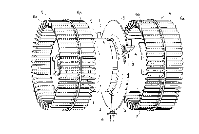
For major clarity the description continues with reference to the enclosed
drawings which are intended for purposes of illustration and not in a limiting
10 sense and which illustrate two structurally different embodiments of the sameinvention, one consisting of two adjacent and spaced augers and the other
consisting of three adjacent and spaced augers.
Figures 1 and 2 refer to the first embodiment while figures 3 and 4 refers to
the second embodiment.
15 - figures 1 and 3 are two axonometric views of the fan-motor according to the invention in the above two structural embodiments;
- figures 2 and 4 are the cross-section of the casing housing the fan-motor
illustrated respectively in figures 1 and 3.
With reference to figure 1, the motor (1) of the suction unit in question is in
20 part housed in a cylindrical cover (2) provided externally with three radial arms
(3) placed at 120~ two of which are turned upward and one is turned
downwards, all terminating with respective pins having vertical axis (4) each
with enlarged end base (4a).
In the case of the embodiment according to the invention illustrated in figure
25 1, said radial arms (3) are incorporated in a disk (5) realised outside the
cylindrical cover (2).
Two fans (6) of the type consisting of a ring having a respective series of
blades (6a) on its two faces are splined at the ends of the through shaft of themotor (1) - namely on the right and on the left of the motor (1).
30 With reference to figure 2, the casing (7) consists of two adjacent augers (8)
spaced by a gap (9).
Both the sides of each auger (8) are provided with suction inlets (8a and 8b),
the first (8a) on the external side and the second (8b) on the internal side.

CA 02223313 1997-12-02
Figure 2 shows the arrows illustrating the flow of air drawn through both the
two external suction inlets (8a) and through the two suction inlets (8b).
The number (10) refers to two of the three bushings fitted in the space (9)
designed to house the pins (4) provided at the ends of the radial arms (3)
5 projecting from the cover (2) to ensure secure fixing of the fan-motor unit to the casing (7).
It is evident that the above disk (5) provided on the exterior of the cylindrical
cover (2) is positioned between the two opposing inlets (8b) provided in
proximity of the internal sides of each auger (8); said disk (5) has an accident10 prevention function, nameiy that of preventing the operator from inserting a
finger into said suction inlets.
A detailed description of figures 2 and 4 is not considered to be necessary in
that the only difference in the second structural embodiment of the invention
with respect to the first embodiment is the use of three spaced and adjacent
- 15 augers (80) separated by respective spaces (90).
In the second embodiment there are three fans (6) despite the fact that there
is only one motor (1).
In this regard it should be noted that the same numbers used in figures 1 and
3 were used in figures 2 and 4 to illustrate the corresponding structural
20 components in the first and second embodiments of the invention.

Dessin représentatif
Une figure unique qui représente un dessin illustrant l'invention.
États administratifs

2024-08-01 : Dans le cadre de la transition vers les Brevets de nouvelle génération (BNG), la base de données sur les brevets canadiens (BDBC) contient désormais un Historique d'événement plus détaillé, qui reproduit le Journal des événements de notre nouvelle solution interne.

Veuillez noter que les événements débutant par « Inactive : » se réfèrent à des événements qui ne sont plus utilisés dans notre nouvelle solution interne.

Pour une meilleure compréhension de l'état de la demande ou brevet qui figure sur cette page, la rubrique Mise en garde , et les descriptions de Brevet , Historique d'événement , Taxes périodiques et Historique des paiements devraient être consultées.

Historique d'événement

Description Date
Inactive : CIB de MCD 2006-03-12
Le délai pour l'annulation est expiré 2001-12-03
Demande non rétablie avant l'échéance 2001-12-03
Réputée abandonnée - omission de répondre à un avis sur les taxes pour le maintien en état 2000-12-04
Demande publiée (accessible au public) 1998-06-06
Inactive : CIB attribuée 1998-03-23
Inactive : CIB en 1re position 1998-03-23
Inactive : CIB attribuée 1998-03-23
Symbole de classement modifié 1998-03-23
Inactive : Certificat de dépôt - Sans RE (Anglais) 1998-03-16
Demande reçue - nationale ordinaire 1998-02-26
Exigences de dépôt - jugé conforme 1998-02-26
Lettre envoyée 1998-02-26
Inactive : Certificat de dépôt - Sans RE (Anglais) 1998-02-26

Historique d'abandonnement

Date d'abandonnement Raison Date de rétablissement
2000-12-04

Taxes périodiques

Le dernier paiement a été reçu le 1999-10-18

Avis : Si le paiement en totalité n'a pas été reçu au plus tard à la date indiquée, une taxe supplémentaire peut être imposée, soit une des taxes suivantes :

  • taxe de rétablissement ;
  • taxe pour paiement en souffrance ; ou
  • taxe additionnelle pour le renversement d'une péremption réputée.

Veuillez vous référer à la page web des taxes sur les brevets de l'OPIC pour voir tous les montants actuels des taxes.

Historique des taxes

Type de taxes Anniversaire Échéance Date payée
Enregistrement d'un document 1997-12-02
Taxe pour le dépôt - générale 1997-12-02
TM (demande, 2e anniv.) - générale 02 1999-12-02 1999-10-18
Titulaires au dossier

Les titulaires actuels et antérieures au dossier sont affichés en ordre alphabétique.

Titulaires actuels au dossier
F.I.M.E.-FABBRICA ITALIANA MOTORI ELETTRICI S.R.L.
Titulaires antérieures au dossier
ALBERTO BACCHIOCCHI
Les propriétaires antérieurs qui ne figurent pas dans la liste des « Propriétaires au dossier » apparaîtront dans d'autres documents au dossier.
Documents

Pour visionner les fichiers sélectionnés, entrer le code reCAPTCHA :


Pour visualiser une image, cliquer sur un lien dans la colonne description du document. Pour télécharger l'image (les images), cliquer l'une ou plusieurs cases à cocher dans la première colonne et ensuite cliquer sur le bouton "Télécharger sélection en format PDF (archive Zip)" ou le bouton "Télécharger sélection (en un fichier PDF fusionné)".

Liste des documents de brevet publiés et non publiés sur la BDBC .

Si vous avez des difficultés à accéder au contenu, veuillez communiquer avec le Centre de services à la clientèle au 1-866-997-1936, ou envoyer un courriel au Centre de service à la clientèle de l'OPIC.


Description du
Document 
Date
(aaaa-mm-jj) 
Nombre de pages   Taille de l'image (Ko) 
Page couverture 1998-06-16 1 49
Abrégé 1997-12-02 1 8
Description 1997-12-02 4 170
Dessins 1997-12-02 4 166
Revendications 1997-12-02 1 21
Dessin représentatif 1998-06-16 1 17
Courtoisie - Certificat d'enregistrement (document(s) connexe(s)) 1998-02-26 1 118
Certificat de dépôt (anglais) 1998-02-26 1 165
Certificat de dépôt (anglais) 1998-03-16 1 165
Rappel de taxe de maintien due 1999-08-04 1 114
Courtoisie - Lettre d'abandon (taxe de maintien en état) 2001-01-02 1 183
Taxes 1999-10-18 1 28