Note: Descriptions are shown in the official language in which they were submitted.
CA 02224001 1997-12-08
WO 96/42024 PCTrUS~6~'~3232
RETROREFLECTIVE CUBE CORNER ARTICLE
HAVlNG SCALENE BASE TRIANGLES
S FIELD OF THE rNVENTION
The present invention relates to r~L,ul ~lective articles having structured
sllrf~~es In particular, the present invention relates to r~l-olenective ~heetin~ having
a sL~ ul~d surface that in~l~ldes cube corner I~I-ul~,nective e1P ~ having scalene
base I ~ ;~n~IF~S and to molds for follluhl~, the sarne.
BACKGROUND
Retroreflective articles that rely upon cube corner leLIùr~:nective Pl~."~
have gained wide acc~pl~ce in applic~;or~c relating to traffic and pel~ol~al safety
lll~l h~g,. Cube corner r~:tlur~flective ~heetin~ is widely used to f~nh~nce the visibility,
lS or conspic~lity~ of road signs in poor lighting conditions and at night. Cube corner
ul~;nective ~1-P~l;ng has also gained wvide ..ccepl~-ce in vehicle con~picuity
...~.L;.,~ related applic~tion~ For PY~mrle, in the United States, govellu~ t
re~ tion~ require lelror~le~;live materials to be positio~ed on serni-truck trailers to
iullplove the ce ~ ity ofthese vehicles. Other applic~tionc for cube corner
20 l~llul~flective ~l.re~ , include l~,llultinective ~ for use in high-visibility
clothing.
The basic cube corner l~t~ûl~ective element is well knûwn in the
illu~enective arts. This element is generally a trihedral structure having threemutually sul,~l~llially perpendicular lateral faces which intersect at a single ler~l ence
2~ point, or apex, and a base triangle opposite the apex. The symmetry axis, or optical
axis of the element is the axis which extends through the cube apex and trisects the
internal space of the cube corner ~ m~nt In operation, light inf id~nt upon the base
ofthe cube corner ~l, .n--..l is r~flected from each ofthe three lateral faces and is
l~.lh~;-;led toward the light source. Reflection from the lateral cube corner faces may
30 be achieved through specular reflection, in which case the lateral faces of a cube
corner el~.nc~-l are coated with a spec~ rly reflective subst~nce such as, for
~'e, ~1.. ;~.. or silver. Alternatively, reflection may be achieved pursuant to
principles of total internal reflection, in which case the faces of the cube corner
CA 02224001 1997-12-08
W O 96/42024 PCTAJsgCo~232
~lc~ are not coated with a specul~rly reflective material. Retroreflective ~eheeting
generally h~col~,ul~les a structured surface inC~u~ing at least one array of cube corner
reflective P~ to enh~nce the visibility of an object. The total light rc~ cflected
by the ~he~l iug is the sum of the light r~,L~. ~ cnected by the individual cube corner
S
The term 'c.l~ ce angularity' is commonly used to describe the
re~orcnec~ e pc~ru~ ce of le~ ellective $heclin~ as a function ofthe elll,~lce
angle of light inc;~Pnt on the eheeti~ and the oriPnt~tiQn of the ~hC~ p The
e,lt~ ce angle of inridçnt light is typically measured with respect to an axis that
10 extends normal to the base surface ofthe eheetin~ The rellolcnective pc,ro"..ance
of an article may be c,~ ssed as a pe.ccnlage of the total light inC;dpnt on the face of
the article which is returned by the article at a particular entrance angle.
ConvPntis)n~l truncated cube corner lcllol~cflective rlr--~ ; exhibit poor
c,ll~ ~lce angularity. The amount of light l cl, ~ nected by a conventional cube-
5 corner el~ l drops sharply when the e.lLl~-ce angle of incidPnt light deviates from
the optical axis ofthe Pl-omP!nt Similarly"cl,or~,llec~ e eheetinP which employs non-
canted, trlmc~ted cube corner e1. .,.~ c exhibits poor rcllorcnective pc,r~,l,llance in
~SpOllSe, to light which is inrident upon the sheeting at high entrance angles.
Many app!i~tionc could benefit from rc~lorcnective cheeting that exhibits
20 broad e~ ulce angularity in ml-ltiple planes. One such applic~tion relates torclr(,lcIlective com~;c~;ly chP~ti~g for the trucking industry. Truck conspicuity
She~ R. is typically placed on the rear and the sides of truck trailers in both a
ho. ;,Ol.~i~l o,i~ ;on and a vertical orientation relative to the frame of the trailer. To
fimr.tion c~cc~ ly, the cheeting must lcllolcflect light in~i~lçnt on the trailer at high
2s ~IIl~lncC angles when the sheeti~ is positioned in either orientation. Accordingly, it
would be dw;l~ ble to provide rcllo,tIlective truck conspicuity !'hr~ which
exhibits broad entrance angularity in two planes. Signing applications would also
benefit from rcl~u~ ective cheeting having broad entrance angularity in multipleplanes. In particular, ~c~lulcnective cheeting having multiple planes of broad
30 ellllnllce angularity reduces the importance of positioning .cheesing at a particular
o,ie.ll~lion on the sign.
CA 02224001 1997-12-08
WO 96/42024 PCT/U~CI~232
One method of producing, el, o, ~nective article having broad e.,l- ~ce
angularity in mllltill~e planes, commonly known in the art as 'tiling', involves~-~-~ng a plurality of discrete tiles of canted cube corner arrays at di~er~
Ol;~n~ on the ChP.~ g, FY~mPt~e of p~blir~tions relating to tiling include
s Tiling has the advantage of el~ ely producing an article with multiple planes of
broad entrance angularity. However, tiling has the inherent disadvantage that, at any
given o,ie~ lion, only a fraction of the tiled sections are oriented to ~ rOItllect the
m~imllm amount of light ;..-,id~ on their surface. As a result, tiled cube corner
~hreting suffers an inherent loss in brightnrq~ at any given o~ l;ol~ to gain ~Illtirle
planes of e"l,~nce ~ngnl~rity.
U.S. Patent 4,588,258 discloses a ltil,o~nective article which has two planes -
of broad elll~ce angularity: a first plane which is substantially coinritlPnt with the
plane which inrl~ldes the optical axes ofthe cube corner el~ ls and a second plane
which is pe",~n~lir,lll~r to the first plane. However, this article exhibits sul;,~ ;ally
1S broader e.,l,~ce al~uLuily in the first plane than in the second plane.
It would be desirable to provide a rel,olenective ~heeting that has two broad
planes of e.,l~lce angularity which exhibit ~Ubs~ ly similar rell ol enective
p~lrul'.'allce at non-zero enl,ance angles. It would be ever more desirable to provide
a sheeting which could achieve this optical prope. ly without sacrificing brightn~s~, as
r~uiled by tiled cube corner .~he~ g The art neither discloses nor s~lg~est~ such an
article or a manner of achieving such an optical pl ope, ly.
SI~IMARY OF THE INVENTION
The present invention is directed toward cube corner I~IOl~nective ~heeting
2~ that exhibits improved t;"h~ce angularity in one or more planes and toward master
articles and molds for m~mlf~r.tllring the same. Briefly, according to one aspect of
the invention the present invention provides a retroreflective cube cornem~l~e~
co.~ .g a ~u~ le having a base surface disposed in a base plane a structured
surface .1i~ ~ced from the base surface The structured surface incll~des an array of
~ 30 cube corner elemrnt m~tçhed pairs formed by three inte, ~e~li"g sets of s~lbst~nti~lly
parallel grooves. Only two groove sets intersect at an angle less than 60 degrees; and
CA 02224001 1997-12-08
W O 96/42024 PCTrUS~5232
a pluratity of cube corner ele-ne"l~ in the array co",~.ise a base triangle bounded by
one groove from each of the three inte. ~ec~il.g groove sets, the base triangle being
scalene.
Acco,dillg to another aspect, the invention provides a lel,ol~neclive sl,c.,li"g5 formed from a s-~lJs~ l;AIIy optically l.~u,~,.,t l"aLe,ial co."~,.isi..g a substrate
having a base surface disposed in a base plane and a structured surface di~aced
from the base surface. The structured surface inrl~ldes an array of canted cube corner
el~ m~t~hed pairs formed by three mutually i"~e,~ecling sets of ~ub~ lly
parallel grooves, each .~t~l.ed pair in~ i~ a first cube corner clc.ne..l and an0 optically opposing second cube corner el~m~Pnt A plurality of cube corner Ple~ "~
in the array co-.-plise a base triangle bounded by one groove from each of the three
inte.~e.;li..g groove sets that is sc~iene Additionally, a plurality of cube corner
el- ...-..1~ in the array have their ~"...,~l.y axes canted in a first plane and the .~heetin~
exhibits its broadest range of enl-~lce angularity in a second plane that is angularly
lS d ,'-~ed from the first plane.
BRIEF DESCRIPTION OF THE DRAWrNGS
Fig. 1 is a m~gnified plan view of a portion of one embodiment of a cube
corner article in accold~lce with p~ 'r t~- of the present invention;
Fig. 2 is a cross-sectional view of the cube corner article depicted in Fig. l;
Fig. 3 is a graph of isob- ;yhl ~.css curves clepicting the predicted leL~ ort;~lective
pe.r.,l--.~ce of a r~tl-,.t;nu,li~e article in accordance with the article depicted in Fig.
l;
Fig. 4 is a graph of isob.;gl.l..~s curves clepicting the measured ~t;llol~lective
2s p~,.r~,..l.~ce of a l~l.or~;ne.,~ e article in accordance with the article depicted in Fig.
l;
Fig. 5 is a graph ofthe total light return as a function ofthe elll-~ilce angle of
inf~ nt light for the cube corner gPQmet~ depicted in Figs. 1-2;
Fig. 6 is a graph co---p~ ;--g the total light return as a function of the entrance
30 angle of in-~;dPnt light for the cube corner geometry depicted in Figs. 1-2 with a
dirrt.cl.~ cube corner gec~ r,t~y;
-
CA 02224001 1997-12-08
W O 96/42024 PcT/v~ 232
S
Fig. 7 is a sçhf~ ic view of one embodiment of cube corner Iellùrenective
sl-P~ g in accoldance with plillciplos ofthe present invention;
Fig. g is a p~ . :.peclive view of a motor vehicle illustrating one application of
the ~h9c~ g depicted in Fig. 7 as truck conspicuity eheetir~;
s Fig. 9 is a pel :".e~ e view of a rell ul enective ~hev~ which employs
scalene base triangle cube corner Pl~mPntc;
Fig. 10 is a graph of isobri htness curves depicting the predicted
rt;l.u.t;nective pc.~",-~ce of a ~~L~ùr~Ilective article in accordance with the article
d-opicted in Fig. 9;
Fig. 1 1 is a pc~ ~,eclive view of a rell ùrenective ehPetin~ which employs
scalene base triangle cube corner ~ e
Fig. 12 is a graph of isobrightnees curves depicting the predicted
~el~u.t;nective l)t;.r~,-...ance of a r~l.o.enective article in accordallce with the article
clepicted in Fig. 1 1;
Fig. 13 is a s~hPm~tic plan view of a cube corner rt;lru, t;nective eheetin~ in
acco..l~ce with prin~irles of the present invention;
Fig. 14 is a srh~ ;c plan view of a co~ e~;;ally available cube corner
r~llult;nective eh~eting;
Fig. 15 is a graph co,--pali,-g the optical pe,ro"llance ofthe eheeting
20 illustrated in Fig. 13 with the ~h-oetin~ illustrated in Fig. 14;
Figs. 16a-16j are isobrightnP-ee graphs illustrating isobrightness profiles of
cube corner ~eL~olenective element m~t~hecl pairs over i"c,- a;,i~lg cant angles.
Figs. 1, 2, 7-9, 11, 13, and 14 are not drawn to scale.
DETAILED DESCRIPTION
The present invention provides cube corner ~Llul ~llective articles that exhibiti"~l)roved optical l)t;,ru",.ance characteristics. One embodiment ofthe present
invention is directed toward providing a relrol~nective eheetinE that exhibits
improved ~ allce angularity in at least one plane. While not neCçes~y~ it is
30 l~r~ rtied that an article in accordance with the present invention has at least two
planes of broad ~ ance angularity. It is even more plert;ll~d that an article in
CA 02224001 1997-12-08
W O 96/42024 PCTAUS96~3232
acco.dance with the present invention returns substantially the same amount of light
at a given ~ cc angle in either plane of broad entrance angularity.
One aspect ofthe present invention lies in the ~ecogllllion that certain
as~.. ~,lions implicit in prior cube corner terhnrJlogy do not hold true for all cube
s corner geolllctl;cs. In particular, one important assumption implicit in prior cube
corner technology is that canting the optical axes of cube corner el~m-F~nts through a
given angle in a particular plane improves the entrance angularity of the article in a
plane that is subs~ ly parallel to the plane that co..~ C the optical axes ofthecube corner _IF ~r ~ and p~ n~iaJ1~r to the base plane ofthe sheefing The
10 present t1i~rl~ s~lre demor~ les that this as~w.l~lion is not accurate for all classes of
cube corner ge~ ias. A second aspect of the present invention lies in the
recognition that the optical pel roll~dl-ce of retl ~renective articles that have planes of
broad entrance all~,ul~lily that are not co;ncident with the plane in which the optical
axes of cube corner el~ Iie may be improved by ~ligning the planes of broad
lS C.lll~u~CF angularity at a particular O~ llalion angle relative to an edge ofthe
F~eL;~ ~g P~,rel~bly, the broad planes of entrance angularity should be o-i~nledapprox;.~ P,ly parallel with one ofthe edges ofthe shp~eting
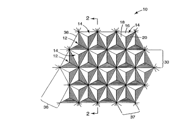
Fig. 1 is a m~grlified s~ ic plan view of a portion of a structured surface
10 of an article that inrludes a plurality of cube corner plPmPnt~ 12, 14 formed by
20 three mutually i.lle.~e.;ti,-g groove sets in-~.lu-ling a primary groove set 30 and two
sets of secondary grooves 36, 37. Cube corner elements 12, 14 have three
a~,r~,.;...~ lely mutually perpen~lic~ r faces 16, 18, 20 and a base triangle bounded
by one groove in each ofthe three groove sets in the ~ubsll~te. The .J;~ ce
~e~ n ~ cPnt grooves in each groove set preferably measures between less than
2~ about 600 microns and more preferably measures about 150-200 n.. cl~ ns, however it
should be applc~;aled that the precise measuré---~,.-ls ofthe cube corner el- ~ are
not critical. The inrhlded angles of the base triangles of the cube corner PlemPnt~ 12,
14 d~ te d in Fig. 1 measure app~ ely 65 degrees, 65 degrees, and 50 degrees,however, the particular geo---el- y of the base triangle of cube corner elements 12, 14
30 is not critical and it will be appreciated that the present invention is not limited to
cube corner el~ s having these specific base triangle measult;..-enls.
CA 02224001 1997-12-08
W 096/42024 PCTAUS96~ 232
The deci~tion of groove set 30 as a pl hl~aly groove set and groove sets 36,
37 as secon~ y groove sets is f?~senti~lly an albill~ly convention. For cube corner
x that have icoscPIP~ base trig~lec, such as the cube corner Pl~mP~nte depicted
in Fig. 1, the second~ry groove sets 36, 37 have sub~ ly identi-f ~l groove angles
s (e.g. 38.721~). By CO~llla~l, the groove angle al of the p.;.. a-y groove 30 (e.g.
27.795~) differs from the groove angle of second~y groove sets 36, 37. By adopting
the co..~..lion of de~;gnA~ , one groove set as a p-in-~ly groove set, the oriP~nt~ti~?n
of a cube corner array relative to the edge of the substrate upon which the array is
disposed can be defined by the angle at which the plilllaly groove set 30 Lll~-se~ls
10 the edge of the substrate.
Fig. 2 is a cross-sectional view of a portion of an article 2 having a structured
surface 10 as depicte(l in Fig. 1. Article 2 in~ des a s.~ lale 4 which, when laid
flat, has a base surface 6 disposed in a base plane and a structured surface 10
d;~l - eed from base surface 6. The material from which ~ub~ll ale 4 is formed may
15 vary d~pP.~ P upon the particular application for which article 2 is suited. Suitable
m~teTi~lc for di~re.~..l applic~tion~ are ~~ sed below. ~ ition~lly, in the
embodiment illu~ led in Fig. 2, structured surface 10 is opposite ~orn, and
~ubsl~lially co-planar with, base surface 6, however, it will be applc;ciated that
structured surface 10 need neither be directly opposite from, nor co-planar with,
20 base surface 6.
Refe..i.lg to Fig. 2, the syrnmetry axes 24, 26 of cube corner elP-~P~.Is 12,
14 are canted through a cant angle, a, of appro~i-,-a~ely 7.47 degrees from an axis
28 that extends ~ubsl~lially normal to base surface 6 and intersects the apex of the
respective cube corner ~ 12, 14. It will be apple-,iated, however, that the
precise cant angle, a, is not critical and the present invention co~lenlpla~es a range of
cant angles ~ - k ~ from about 4 degrees to about 15 degrees. In the embodiment
illustrated in Fig. 2, cube corner ~hPmPntC 12, 14 are canted in a plane that isapp,ox;~ y perpenrlic~ r to p,i,.,a,y groove 30. More precisely, cube corner
e~ 12, 14 are canted such that the symmetry axes 24, 26 lie in a plane that is
- 30 a~)~lox;~ ely perppn~liG~ r to primary groove 30 and to base surface 6. Canted
cube corner elf -~f~ such as those depicted in Figs. 1-2 may be referred to as
CA 02224001 1997-12-08
W O 96/42024 PCT~US9G~232
'backward' canted cube corner PIF-mPnt~ Bachvard canted cube corner PIPmPn
may be further characterized in that only one in~luded angle of the cube corner
~1~n~. .11 base triangle measures less than 60 degrees; the other two int~lnded angles
."easure at least 60 degrees and, in the embodiment illustrated, measure about 65
s degrees. By co~ , rc,l w~ ~l canted cubes may be characterized in that two of the
in~ de~ angles ofthe base triangle measure less than 60 degrees and a single base
triangle included angle ",easures greater than 60 degrees.
Fig. 2 also shows that the groove side angle al of primary groove 30
measures al~p,~ ely 29.795degrees. ~Itho~lghnotshowninFig.2,thegroove
side angle of second~y grooves 36, 37 measure a~,u~ hl ely 38.721 degrees.
Retroreflective eheeti~ inco,pG,~li"g cube corner ek-.~P,~ subst~nti~lly as depicted
in Figs. 1 and 2 is disclosed in U.S. Patent No. 2,310,790 (Junge.se~
Fig. 3 is an isobri~htness contour graph illustrating the predicted total light
return for a ,el,o,t;nective cube corner element m~t~hed pair formed by bac~w~d
15 canted cube corner ~l- ."- ."~j 12, 14 formed from a material having an index of
refraction of 1.517 at varying enl,~nce angles and orientation angles. Predicted total
light return for a cube corner m~t~hed pair array may be c~lc~ ted from a knowledge
of percent active area and ray intensity. Total light return is defined as the product of
percent active area and ray ",lensily. An PYCPllpnt diecusQ;on of total light return for
20 directly ...~ h;..~d cube corner arrays is presented by Stamm U.S. Patent No. 3,812,706.
For an initial unitary light ray intensity, losses may result from two pass
l~ne...:,C on through the base surface of the ~I.Pe~ and from reflection losses at
each of the three cube surfaces. Base surface tr~nemie~eion losses for near normal
in-;~l.on~e and a eheeting refractive index of about 1.5 are roughly 0.92. l~eflectinn
losses for cubes which have been reflectively coated depend for ~ )Ic on the type
of coating and the angle of inc;dence relative to the cube surface normal. Typical
r~fleGtior coefficients for alumimlm reflectively coated cube surfaces are roughly 0.85
to 0.9 at each of the cube surfaces. Reflection losses for cubes which rely on total
internal reflection are ess~pnti~lly zero. However, if the angle of in(idence of a light
ray relative to the cube surface normal is less than the critical angle, then total
CA 02224001 1997-12-08
W O 96/42024 PCTAUS~.~J~g2~2
internal reflection can break down and a ~i~nificsnt amount of light may pass through
the cube s~lrfs-ce. Critical angle is a function of the refractive index of the cube
msterisl and of the index of the material behind the cube (typically air). Standard
optics texts such as Hecht, "Optics", 2nd edition, Addison Wesley, 1987 explain
s front surface 1~ cn losses and total internal reflection.
Effective area for a single or individual cube corner ~lem~nt may be
dclelll..ned by, and is equal to, the topological intersection ofthe projection ofthe
three cube corner surfaces on a plane normal to the re~acted in~;d.ont ray with the
pr~je-~ion ofthe image surfaces ofthe third reflection on the same plane. One
0 procedure for dt:le----mi-lg effective ap~,.lu-~ is tlicc~ ed for example by Eckhardt,
Applied Optics, v. 10 n. 7, July 1971, pg. 1559-1566. Straubel U.S. Patent No.
835,648 also ~iecusses the concel)l of effective area or aperture. Percent active area
for a single cube corner elemt:.-l is then defined as the effective area divided by the
total area ofthe proje~ion ofthe cube corner surfaces. Percent active area may be
5 r,~slr,nlsted using optical modelin~ terhniq-les known to those of or~ .a,y skill in the
optical arts or may be detelll--lled numerically using conventional ray tracing
te~ s Percent active area for a cube corner ....~14l~çd pair array may be
e~lcl-lsted by averaging the percent active area ofthe two individual cube corner
P1~rn~.nt~ in the ...~l~ hed pair. Allt~ ,ly stated, percent active apellu-e equals the
20 area of a cube corner array which is r1l,o-çnecting light divided by the total area of
the array. Percent active area is ~ffected for eY~mple by cube geol.leLIy, refractive
index, angle of inri~l-onr,~, and ~heetins~ orientation.
R~;~l-ill~, to Fig. 3 vector Vl l~plesel-ls the plane that inr.l.ldes the sy.l--lle~ly
axes24, 26 of cubecorner~le~ 12, 14. Forexample, inFig. 1, vectorVl liesin
2s a plane s~L~Ilially perp~ontliclll~r to primary groove 30. The concentric
isobrightness curves I cpl ese--l the predicted total light return as a ,oercenlage of the
light inr;~Pnt on the base surfaces of cube corner ~1em~onts 12, 14 at various
col..l)inalions of entrance angles and orientation angles. Radial movement from the
center ofthe plot ~ s~ increasing entrance angles, while ch~;u.~c;nlial
30 r"ovt;.,.e.-l ~~ ;sellls r,h~nging the orientation ofthe cube corner elrmlont with
respect to the light source. The innermost isobrightness curve de---a~ cales the set of
CA 02224001 1997-12-08
WO 96/42024 PCTAJS9G~5232
e~ ce angles at which a m~tçhed pair of cube corner Fl~mFntc 12, 14 return
applox;...~lF,ly 90% of light incjdent on their base triangles. .~lcc~csively outlying
isob~ .e.ss curves d~."al~,ale c..~ ce angles which return s~lccçssively lower
pclcl .I ~es of light inl~;dent on the base triangles of f ~ 12, 14.
s Fig. 4 is an isobrightnecq graph, similar to the graph pre~ellled in Fig. 3, that
illustrates the measured total light return of a cube corner element m~t~ ed pair
having the same ~eoln~tl~/ as the cube corner element ...A~çl-ed pair depicted in Figs.
1 and 2. The cube corner ~ " .1~ are formed from BK7 glass, which has a
~ia~ilive index of 1.517. ~Itho~gh slight variations in the plots exist due to
lo m~nllf~ctllring i",p.,.reclions and meas-lle-n~.,l errors, the measured results illu~llaled
in Fig. 4 confirm the shape of the isob, ;gl~ ess profile depicted in Fig. 3 .
Two aspects of the isobrightness plots illustrated in Figs. 3-4 should be noted.First, the plots dt;lllonsllale that a ~Atehed pair of cube corner cle-.~ 12, 14 has
two planes of broad e.,l, ~lce ang~ ily that are s~lbsl ~ lly perpPnt~iC~ r to one
another and that lie in a plane that is not coinr;dPnt with the plane in which the cube
corner F~l~nnentc are canted, in~ir~ted by vector Vl. For the cube corner m~tched pair
depicted in Figs. 1-2, the two broad planes of e~lllallce angularity are oriented at
~p~ux;i.~ltly 45 degrees relative to the plane in which the cube corner cl~ 15 are
canted and may be identified on the isobri~htness graphs as two subsla"lially
20 pe.~endicular planes 40, 42 which are coincident with the broad lobes ofth
isobrightness graph.
A second aspect of the isobrightnes~ curves depicted in Figs. 3-4 results from
the fact that cubes 12, 14 are s~ lA~ lly symmetrical about plane V,. Accûldingly,
a ~--~ -ed pair of cube corner ~le ~ having the ~.eQI~ y depicted in Figs. 1-2 will
25 return al)pl.)~ t~ly the same pe,ce.llage of light at a given entrance angle in either
plane 40 or plane 42. This aspect is illustrated in greater detail in Fig. 5, which plots
the predicted total light return of cube corner elem~nts 12, 14 as a function ofthe
enl,~lce angle of light ineident on the base of elomentc 12, 14 in planes 40 and 42.
Curves 44 and 46 rel"ese"l the total light return of a I el~ulenective cube corner
30 ~ F..~ 1F,d pair formed from a material having an index of refraction of 1.6
The two curves are virtually superimposed across the entire range of entrance angles,
CA 02224001 1997-12-08
W 096/42024 PCT~US3~'~232
11
in~ ?tin~ that the total light reflected by the .~A~çl-ed pair is app,o~..-ahly equ~ at a
given c.~ ce angle in either plane 40 or plane 42. The slight di~.~nces above 60~
result from .. i~ Al errors in p,~U~ * p~,.ro--ll~lce for cubes at very high
~ ~n~ ce angles. Curves 48 and S0 are analogous curves for a .c~-urenective cube
s corner c~ -hed pair formed from a material having an index of refraction of 1.5.
Fig. 6 cO~ S the r~lr~r~le~liv-e ptlr~"",~lce ofthe cube corner element
l,fd pair geG~ y d., ~e~ in Figs. 1-2 with the ru. w~d canted cube corner
e1/ -"~ C'l~p~d pair B~~~ dep--~ted in U.S. Patent 4,588,258 (the '258 patent).
0 Curve 52 plots the total light return as a function of entrance angle in the broadest
plane of enl ~ ce angularity in the '258 patent ~omet~ This plane is id.-ntifi~d as
the 'X' plane in the '258 patent. Curve 54 plots the total ligh~ return as a function of
c~ ce angle in the second broadest plane of e.,~ ce angularity in 258 geometry.
This plane is identified as the 'Y' plane in the '258 patent. Curves 56 and 58 plot the
lS total light return as a fimCtio~ of entrance angle for the two broad planes of e .I~ ce
angularity for the ~.~o,..- I~y depiGted in Fig. 1. Fig. 6 d~ on~ tes that, at c.~ ce
angles of greater than about 35-40 degrees, the cube corner F~ mAt~hed pair as
dF~i~-1~1 in Fig. 1 retums a greater pel~,~,nl&ge of light in both planes of broad
el,l,~ce Angl~lAnty 40, 42 than the peo...~y dep;cted in the '258 patent returns in
20 the 'Y' plane.
Fig. 7 is a srl~P ~A~ic plan view of a ,t;~lesenl~ re r~Lrort;nective ~heeting 60
that has two broad planes of e l-L-~ce angularity in acco,dance with p,inci~lcs ofthe
present invention. ~heeti~ 60 inrludes first and second longit~ inAI edges 62 and a
structured surface ~ n.,~;AIIy as desc~ ed in connection with the structured surface
2s depiA,ted in Figs. 1-2. The structured surface in~ludes an array of cube corner
,"A1~.hl~d pairs defined by three inte.:ie~Li-lg sets of substantially paraUel
~ooves incl~l~ing a plilllaly groove 66 and two sets of secondary grooves 68, 69.
neÇA~e the cube corner el~ nt~ have isosceles base triangles, two ofthe base
in~ ded angles are the same. The primary groove set may be defined as the groove30 set joining the two equal angles of the base triangle. The re., ~ groove sets may
be considered seconclaly groove sets. In the embodiment depicted in Fig. 7, the array
CA 02224001 1997-12-08
W O 96/42024 PCTfUS~'03232
12
extends ~ubsl~lially entirely across the surface of the sheeting Each m~tched pair of
cube corner çlFm~nt~ in~lu~les two opposing individual cube corner CIC~I~GIIIS 70, 72
canted in a plane s~ ;Ally perpen~lic~ r to plhll~y groove 66. Additionally, a
major portion of subs~ Ally every primary groove 66, and preferably the entire
s ~ y groove 66, lies in a plane that inl~ a lon~tu-linAl edge 62 of the article
at an angle, a, that plt;rt;lably ~--eas-lrcs app-u~ lPly 45 degrees. It should be noted
that the structured surface is greatly magnified in Fig. 7 for illustrative purposes. In
practice, the ~ re between ~ cent grooves typically me&~ul es between about 60
and 600 m: Ol s.
o Although opposing cube corner el~ s 70, 72 of each m~tl hed pair
del: cted in Fig. 7 are physically located directly opposite primary groove 66 from
one another, it will be app- ec;aled that such relative physical location is not a
r~uh~..~ of the present invention. In its broadest sense, the term 'opposing', as
used herein may be construed to mean optically opposing Cube corner rl~ e~ may
15 be con~;~iered optically opposing when they generate 'mirror image' l~l-u~t;nection
p&lle --s. It is well known in the cube corner ~ t;l~ u- t;nective arts that cube corner
~1F ~ I S which are physical mirror images of one another--that is, F 1~F~ C which are
iAlly idFntic~l but are rotated 180 degrees relative to one another, yield
mirror image ..,~-u.~nective patterns. Direct m~rhinin~ techn~ F ~ make it
20 ndv~ u.-~ to posil;on opposing cube corner elemPnts directly opposite a groove
from one another, as depicted in Fig. 7. However, it will be app-ecialed that
opposing cube corner el~-"~"l~ could be physically remote from one another one the
~,l,F,"~ Additionally, it will be apprccialed that opposing cube corner elF-"....l~
need not be perfect physical mirror images of one another to yield optically opposing
2s cube corner F~ Slight variations in the physical shape of opposing cube corner
P~ will yield only slight variations in the l~l-u~t:nective pattern which are not
~letect~ble by the human eye under normal viewing conditions. Such cube corner
F1FmPntS are still oppo5;,lgF1FmFnh: within the mF~nins~ ofthe term used as used
herein.
A rel.urt;nective ~h-F,eting having a structured surface as depicted in Fig. 7
exhibits a theoretical isobrightn-F,ss proffle substantially the same shape as that
-
CA 02224001 1997-12-08
WO 96/42024 PCTAUS96/09232
13
~lepict~Pd in Fig. 3. However, be~;~use the array of cube corner f lr ~ 1 S iS oliG.,led
such that the plillla.y grooves 66 lie in a plane which intersects the edge ofthe
~hçeting at an angle of appl~ çly 45 degrees, one broad plane of c .,~ ce
angularity, corresponding with plane 40 of Fig. 3, is a~p~o,~;...AIely parallel with the
s longih~ n~l edges 62 of shp~eting 60. The other broad plane of entrance angularity,
coll~ .polldill~ with plane 42 of Fig. 3, is applv~ .A~Pl~ perpen~iC~ r to the
longitu~in~l edges of ~h~ g 60. One of or-lin&,y skill in the art will recognize that
the .GllulGnective pc~r~ .ce of ~I~P~I;U~ 60 may vary from the theoretical
p~;. rO~ ", a~.ct; ~ ,f- ~ r d in Fig. 3 as a result of factors such as m~mlf~ctllring
10 i l*clre.;lions and measurement errors. Such minor variations are considered within
the scope of the present invention.
One applic~tion in which ~ u~enective ~I.ee~ g 60 is particularly
advantageous is in the field of vehicle co~pic~ity ~hçeting Fig. 8 is a schPm~tiC .
depiction of a large vehide 82 having a strip of retroreflective .~hf~etin~ 60 disposed in
lS a h~ ...l ,.l vl ;~ l ;oll and a strip of rGIlvl Gnective ~hçeting 60 disposed in a vertical
O~ nl;Qn Retroreflective ~he~t;~g 60 ~ lulGnects light from the he~-llight~ Of
passing aulvlllobiles to f .h~-ce the conspicuity of vehicle 82. To ...~,c;,..;,e the
amount of light I Glullled by ho. ;,o..l ~lly oriented strip of I ~tl olGnective ~hpeting 60at
high e.ltl~ce angles, its broadest plane of entrance angularity should be ~ubsl~lially
20 parallel with its lon~gitu-lin~l edge62. By contrast, to ...~x;..-;,e the amount of light
returned by vertically oriented strip of ~ olenective sheeting 60 at high enl.~llce
angles, its broadest plane of c ~ nce angularity should be ~lb~ lly perpPn~ir,lll~r
to its lon~yt~ldin~l edge 62.
RetrOref1eCtiVe .~hFel;~g 60 is particularly well suited for such vehicle
2s co-~s~ ity appl;c~ti~m~ When ~heeting 60 is placed on vehicle 82 in the ho.i~o..l~l
Oli~lnl;Qn~ one broad plane of entrance angularity is aligned subst~nti~lly parallel
with the longitu~in~l edge 62 of rcll orc;nective sheeting 60, thereby . ~;1 x;~ ..;,;. .g the
arnount of light relullled by holi~olll~l strip 84 at high entrance angles. Sirnilarly,
when ~heeting 60 is placed on the vehicle in the vertical orientation, one broad plane
- 30 of c.. L~Ice angularity is aligned s l,~ ially perpçn~1iC l1~r to the longit~ in~l edge
62 of-e~-olt;llective sheetin~ 60, thereby ,n~xi...;,.;..g the amount of light returned by
CA 02224001 1997-12-08
W O 96142024 PCT/U'3G~0~232
14
vertical strip 86 at high entrance angles. The ability to supply a single ~1 e~ g
product for this application yields savings in the design, m~m-f~cturing, and
n process for such consp~ e~ g
.~h~eting 60 is similarly adv~ntageo~lc in the highway sign ~h~eting
S appl;rAti~n~ As ~I;c~ c~ed above, the ,.L,o.t;nective pelru""ance of most canted
cube-corner ~I.eel;.~g products is ~~.o.p.on~l~nt upon the orientation ofthe ~heetin~r on
the sign. For ~ ~ ~le, ~ g illu~llal~,d in the '258 patent has better e.,l,~nce
angularity in the plane identified as the X-plane. To ensure the best optical
p~;,f,~ ce from the ~h~eting ofthe '258 patent, the ~l~ee~ g must be oriented such
0 that the X-plane is coinrident with the entrance plane of inA.id~nt light. By conll~sL,
the cl~e~ g depicted in Fig. 7 may be oriented such that either plane of broad
e~ ce angularity is coin~ident with the enl,~llce plane of in- ident light.
For most applicaLions, ~I.eet;~.g 60 exhibits its best ~cl~urt;llective
pe~ 1~" ~ e when one plane of broadest e"l~al,ce angularity is aligned s~"ially
15 parallel with the longitu~linAI edge 62 of sl.ee~ For the cube corner geometry
depicted in Fig. 7, this co"cal,onds to a structured surface in which the major portion
of the p".n~y grooves 66, and pl ~rer;~ly the entire length of each plilllaly groove
66, lies in a plane that inle. ~ecls a lon~tu~lin~l edge 62 of the ~heeting at an angle
45 degrees. However, it will be applc~;;aled by one of ordinary skill in the
20 art that the p,iln&,y grooves need not lie in planes which intersect the edge of a piece
of sheelii~ at exactly 45 degrees. ~Ithough the rcllolcnective bri~htness ofthe
article will de.;leasc as the angle at which primary groove 66 intersects the edge 62 of
the article deviates from 45 degrees, the decl ~ asc will be gradual. De~uendi,,g upon
the p~,.rull,~ance requ;r~,."enls, the advantages of the present invention may be
2S obl~ned with the geometry depicted in Fig. 7 provided primary groove 66 intersects
the edge 62 at an angle that measures between about 35 and 55 degrees and more
preferably bct~een about 40 and 50 degrees. Additionally, numerous other cube
corner ~ . ies exist that have planes of broad entrance angularity angularly
di~pl~ced from the plane in which the optical axis of the cube corner element is30 canted. One of ol dh~&~y skill in the rcl~ ul cnective arts will a~precidle that the
pclfwlllal~ce of l~ ùlenective ~l.eel;~ incorporating such cube corner elem~nts may
CA 02224001 1997-12-08
WO96/42024 PcT/u'~Gl~5232
lS
be improved by o-i~.. Led the cube corner ~ such that the broad planes of
e ~ll~lce angularity are aligned sllhs~ l1y parallel with an edge of the ~hPPtit~g
The optical fldvantages of the present invention may be achieved using cube
corner PlP - "_.11 geo---~l ~ ;es other than the geome~ i y depicted in Fig. 1. A broad class
s of cube corner el- -..-,-.l ~ that have scalene base triangles have isobrightness profiles
that are s~it~h~-~ for ,.. ..-r, ,I...",g ~ u~enective ~ g in a cco~dance with aspects
ofthe present invention. Scalene base triangle cube corner ~-IF..n~l.le may be
characterized in that none ofthe three in~ ded angles ofthe cube corner element
base triangle are the same.
One PY~mple of structured surface 100 employing a ~ .llali~e scalene
base triangle cube corner element geon.cl~y is dep;cted in Fig. 9. The ;nrlllded angles
of the base triangle of each cube corner ~el~lt;nective element Illeavule
approx;~ ely 62.09 degrees, 67.91 degrees, ~nd 50.00 degrees (,BI, 132, and ,B3,especli~ely)~ The groove side angle of groove 102 (a 2) measures ~ro~;.n,-~ely
42.295 deg-ees, the groove side angle of groove 104 (a 1) measures apl,lo,.;in~ly
26.284 degrees; and the groove side ang1e of groove 106 (a 3)"~eavu~S
appro~ ly 36.334 degrees. The optical axis of each cube corner element is
canted a~prox;...-lPly 8.38 degrees from an axis normal to the base surface ofthe
vul,vl ale in a plane that is app~ ,x;~ ely parallel to groove 104 and pel~e~ cul~r to
20 the base surface of the m~t~ri~l
Fig. 10 is a predicted isob,;gl~ s profile of a ,~,u,~nective ~hPetin~
employing cube corner element m~tr.lled pairs formed from a material having a
refractive index of 1.590 and having the g~o...~ y depicted in Fig. 9. Vector Vlcoll.,v,.onds to the plane in which the cube corner PlPmPnt~ are canted (i.e. the plane
2s that col;.;~ the vyll~"~l,y axes ofthe cube corner Pl~mPnt~) The cube corner
g~~ hy depicted in Fig. 9 exhibits two planes of broad entrance angularity, denoted
by planes 110, 112, that are angularly ~ plrlced from the plane in which the cube
corner c~ are canted by applù~ tply 30 degrees and 120 degrees,
respectively. Additionally, planes 110 and 112 are app~uX;.~ ly perp~n~ic -l~r to
- 30 one another. Accol.lh~gly, orienting the structured surface such that groove 104
intersects a lon~ih~lin~l edge of a lel, ~" t;nective ~I.eel ;,.g at either 30 degrees or 120
CA 02224001 1997-12-08
W O 96/42024 PCTAJS96/09232
16
degrees wi11 align one broad planes of e,-l,~lce angularity parallel with the
longit ~ edge of the chPetir~ and another broad plane of entrance angularity
pe.~n~lic~llnr to the lon~h~ n~l edge ofthe sheeti~
Fig. 11 illu~ les a structured surface 120 inc~ i~ another scalene base
s triangle cube corner gf.~O"'~ )r that has two broad planes of c .I~ ce angularity
angularly rl;cp!~ced from the plane in which oppos;"g cube corner clenl~lls are
canted. The included angles ofthe cube corner el~ f -.1 base triangles depicted in
Fig. 11 Illea~ appru~ ely 68.71 degrees, 63.29 degrees, and 48.00 degrees (~1,
and ~3, resl,e~ ely). The groove side angle of groove 122 (a 2)ll-c~i~iul~s
0 al~plu~ lf Iy 42.295 degrees; the groove side angle of groove 124 (a l )measures
applo~ f l~/ 26.284 degrees; and the groove side angle of groove 126 (a 3 )
measures appr~ ,ly 36.334 degrees. The optical axes ofthe cube corner
f~l. -... -.1~; are canted appro~-ll,alely 9.Sl degrees from an axis normal to the base
surface ofthe substrate in a plane that intersects groove 122 at an angle of
al)~,lu~ ely 45 degrees.
As illustrated in Fig. 12, a l~llolt;llective ~l.e~ g that incl~ldes an array ofcube corner e~ as c~epicted in Fig. 11 and having a refractive index of 1.590 has
t~vo broad planes of entrance angularity 130, 132 angularly ~iepl~ced from the plane
in which the ~ are canted Vl by about 26 degrees and 116 degrees,
I~:~e~ ,ly. Accoldin~ly, ulie~ g the structured surface such that groove 124
intersects a longitutlin~l edge of a rtilr-,l c;nective cheetin~ at either 49 degrees or
139 degrees will align one broad planes of c.,ll~-ce angularity parallel with the
longit l-lin~l edge of the cl.Pt ~ g and another broad plane of entrance angularity
p~l~,.... ......,.lir,llls-r to the longjtll~in~l edge ofthe cheeti~
2s Cube corner elc.ll~.,l designs employing scalene base triangles have some
additional ad~ gcs over cube corner elements having isosceles base triangles. One
advantage is that a structured surface having scalene base triangle cube corner
may allow a greater degree of canting of opposing cube corner PIPmPntc in
the m~nllf~ctllring process without causing physical damage to ~dj~cPnt cube corner
e,l~
CA 02224001 1997-12-08
WO 96/42024 PCT~US96109232
17
In directly m~-hined cubes using three sets of mutually i..~ e~,ling grooves,
cube Cl;ppillg occurs when any one of the groove side angles c~ceeds 45~, causing
the cutting tool to clip the edge of an ~jacent cube. A ~l~m~ged cube corner element
results in losses in ~ tinectivity. For ~ , the cube corner element geo~ y
s depicted in U.S. Pat. No. 4,S88,258 cannot be canted beyond a cant angle of 9.736
degrees in a co~ ;on~l array. In Table I, below, leplese.llali~e scalene ~,ec,...f~y
values for base triangle in~ ded angles (13) and groove side (a) angles, are shown for
canting opposing cube corner e~ k~lc in a plane which is roughly parallel to a
groove and perpentliclll~r to the base plane.
10 Scalene geo---ell;es may permit greater ~mollntc oftilt prior to any groove side angle
~Yceeding 45 degrees, thereby allowing tilting of cube corner e1ementc beyond the
known limit~tionc due to ...ec~ ;c~l clipping caused by a cutting tool. For; ,~le7'
Table I df -~o~ les that a tilt or cant angle of up to roughly 13.376 degrees can be
utilized without edge clipping.
CA 02224001 1997-12-08
W O 96/42024 PCT~US9G/~5232
18
Table I
~2 ~3 ~1 al a2 a3 Tilt A~n~e
40.0 73.321 66.679 36.695 21.063 45.789 14.912
S 41.0 72.84S 66.1SS 36.S77 21.677 45.485 14.305
42.0 72.3S8 6S.642 36.464 22.300 4S.161 13.689
42.5 72.110 6S.390 36.408 22.614 44.992 13.376
43.0 71.8S8 6S.142 36.354 22.931 44.818 13.061
44.0 71.34S 64.6SS 36.247 23.S71 44.4SS 12.421
4S.0 70.817 64.183 36.14S 24.221 44.071 11.769
46.0 70.274 63.727 36.047 24.881 43.666 ll.lOS
47.0 69.713 63.287 3S.953 2S.SS0 43.238 10.426
48.0 69.133 62.867 3S.864 26.230 42.787 9.733
49.0 68.533 62.467 35.780 26.921 42.313 9.025
lS S0.0 67.912 62.088 35.700 27.623 41.814 8.300
Sl.0 67.266 61.734 3S.626 28.336 41.289 7.SS9
S2.0 66.S9S 61.40S 3S.SS8 29.061 40.738 6.801
S3.0 6S.896 61.104 3S.49S 29.797 40.160 6.024
54.0 6S.167 60.833 3S.440 30.S4S 39.SS3 S.228
SS.0 64.40S 60.S9S 35.391 31.304 38.917 4.412
56.0 63.607 60.393 3S.349 32.075 38.250 3.574
S7.0 62.770 60.230 35.316 32.857 37.SS2 2.715
S8.0 61.892 60.109 3S.291 33.6S0 36.822 1.833
S9.0 60.967 60.033 3S.275 34.452 36.058 0.927
60.0 60.000 60.000 3S.264 3S.264 3S.264 0.000
In col..l.;.. ~I;on with the teaçhing.c ofthis invention relating to improved
ple~ll ~d entrance angularity not in the plane of cant, scalene base gec l~,~lly cube
comer clcll,e"l arrays also enable tilting beyond previously known limits at which
total light retum breaks down for light incid~nt perpendicular or nommal to the base
of the cubes. Total light retum (TLR) for reLI orenective ch~eting iS derived from the
product of percent active aperture and rell ort:flected light ray intensity. For some
co...l.;.-~l;on.c of cube geQ...~l~ies, entrance angles, and refractive index, significant
red~lctiQn.c in ray inlt;l,~;ly may result in relatively poor total light return even though
3S percent active aperture is relatively high. One ~ ,le is lellu.enective cube comer
CA 02224001 1997-12-08
W O 96J42024 PCTAUS96J'~323
19
f ~ arrays which rely on total internal reflection of the r e~-Ol~nected light rays.
Ray il.tenD;Iy is s~l..s~ ;Ally reduced if the critical angle for total internal reflection is
~Yceeded at one of the cube faces. ~lthough met~ 7çd or other reflective co~ting~
~ may be utilized adv~nt~geQusly in such sittl~tion~ these co~tings are not always
s de~;l~lc due to cost, process, appeal~lce, or other factors. In such ~itl-~tion~, the
use of scalene base triangle cube corner e1~mentc is prer~ d.
Table II shows limiting total light return geometries for normally inc;dçnt 1ight
and cubes with a refractive index of 1.586. For a 52.2~-52.2~-74.6~ base angle cube
comer el- ..- ~-~ the limiting tilt angle is 15.60~, for ~Y~mple as shown in U. S. Pat.
No. 4,588,258 (EIoopman). However, this limit~tion may be ~Yçeeded without totallight return breakdown using scalene base geometries, for example, 16.41~ (45.40~-
58.57~-76.03~) or even 18.830~ (77.358~-65.642~-37.00~). Data in Table II l~iltiSe,lL
mlm~ric~l rather than analytical solutions.
Tuble II
1S ~1 B2 B,3 a, a2 a3 Tilt
7S.600 S2.200 S2.200 50.867 26.505 26.S05 lS.602
7S.749 48.900 S5.351 50.939 24.769 28.080 lS.8S7
76.030 4S.400 S8.S70 S0.924 22.949 29.689 16.408
76.623 41.400 61.977 S0.985 20.840 31.290 17.476
20 77.3S8 37.000 6S.642 S0.816 18.S82 33.064 18.830
Principles ofthe present invention may also be applied to tiled ~~;l-u-~nective
.cl.e~l;..p. As used herein, a tiled structured surface in~ dçs a plurality of discrete
arrays of cube corner elom~nt m~tched pairs positioned at di~rt;-ll oriçnt~tion~2S relative to the edge of the !~hee~ g Tiling is one :~tl~egy employed to produce
~ ,olene~ e ~heeting having multiple planes of broad entrance angularity. Tiled
~etl~l~;nective shçeti~ suffers some inherent loss of bri~htn~ss at high en~ ce
angles because, by definition, only a portion of the arrays are oriented to r t:~- oleLlect
the ..~ .~.h~ .. arnount of light at a given entrance angle and ~heeting orientation.
30 However, it is possible to ...;..i...;~-, or at least to reduce, the bri~htness loss inherent
in tiled !~hf,~ h~B by orienting the arrays of cube corner Plom~nt~ on the structured
surface in acco- d~ce with principles of the present invention.
CA 02224001 1997-12-08
W O 96/42024 PCT~US96~0~232
The utility oftiling may be ~Ypl~ined with .~.felence to the lel-u.~,nective
cheeting d epicted in Fig. 7. As diccllcced above, the structured surface of thecl.olellective .c1.~ 2, d e~ ~ ted in Fig. 7 has a single array of cube corner cl~
m~tr.h~d pairs which results in two broad planes of entrance angularity: a first plane
s s~ s~ ly parallel with a lnngitl~-lin~l edge 62 of ch~eting 60 and a second plane
s~ ;AIlyperpen~lir,ul~to lon it~ in~l edge62 of shc~,Ling 60. Atiled
olcllective ~he.,~ g inrl~ltling a structured surface having two distinct
,ositir~ned at two di~.~ ;onc relative to the edge ofthe ;~heel;n~ may
have as many as four broad planes of c.~ ce angularity. Similarly, a ~cL-u~t~e-;live
0 .cheeting inr.l~l~ing a tiled structured surface having three distinct tiled arrays
positiQ~d at three di~l ~.-l orientations relative to the edge of the she~ may have
as many as six broad planes of e.,lr~1ce angularity. In general, for the cube corner
~eo---e~y d., i~ d in Fig. 7, a lel,orcnective cheeting having a number X broad
planes of c.,l-~ce angularity may be produced by a structured surface having a
lS plurality of tiled arrays positioned at X/2 distinct oriçn~tion~ relative to the edge of
the ~h~etir~g
In acco~dance with the present invention, at least one ofthe arrays of cube
corner element m~trhed pairs should be oriented such that one broad plane of
~,.llla.~cc angularity is positioned appr~X;..~ Iy parallel with the edge ofthe shc~li"g.
20 Acco~.li-.~,ly, for the cube corner el~ment ~eomlo,try depicted in Fig. 7, one array of
cube corner ~1~ .".-,~ .ed pairs should be oriented at such that the plilllaly
groove i..lt;. ~c~,ls the edge of the article at an angle of ap,olox;. ~ .z~ely 45 degrees.
The o-ic..l~lion of the ~ 8 arrays depends upon the number of discrete
arrays of cube corner ~ m~tched pairs in the structured surface. For the cube
25 corner geometry of Fig. 7, a~ 8 that the goal oftiling is to produce a more
rot~tio. ~lly :,y~ ical ~t;l,."~nection pattern, the angular ~lif~,ence ~betweenarrays of cube corner e~ m~tched pairs may be e,~ ssed by the forrnula:
~ = 90/N
where N lt;~.~.se..ls the number of discrete arrays of cube corner f~ ment~ Thus, in a
30 .~;~.o.~flective !~I.edi,~g having four broad planes of entrance angularity (e.g. using N-
2 arrays of cube corner elements) the angular di~,~,nce ~ in the orientation ofthe
CA 02224001 1997-12-08
WO 96~42024 PCTAJS9~ 232
21
cube corner arrays should measure a~ Iy 4s degrees. Accoldill~ly, the
second array of cube corner c~ should be oriented such that the p~h~&ly
groove intersects the edge ofthe article at an angle of app,u,~;...~tely 90 degrees.
Similarly, in a rcl.o~cne~ e ~he~ having six broad planes of entrance ~ng~l1srity
s the di~.~.~ce ~in the ori-P~ Qn ofthe cube corner arrays should ~"e&s.
appru~ fly 30 degrees. Acco,du,~ly, a second array of cube corner e1=.... ~
should be o. i-,-~led such that the p,h~a-y groove intersects the edge of the article at
an ang1e of applv,.;~ y 15 degrees relative to a 1Ongitlldin~l edge of the ~l.cc~ p
and a third array of cube corner elP -~nl ~ should be oriented such that the plhllaly
0 groove i~ e~,ls the edge of the article at an angle of ~y~u~ alely 75 degrees
relative to a longit~l~lin~l edge ofthe ~he~;.lg This progression may be contin-led
lhlo~h as many distinct orientations as desired.
Fig. 13 is a s~ l.- -~. l;c depiction of one embodiment of a tiled rGl~u,t;nective
.d.fel;l~p 150 in accoldance with the present invention which has six arrays of cube
corner fl~ .. lc r~ in six planes of broad entrance angularity. In a pler~"~,~embodimf nt, ret,ù~nective cheeting 150 is m~mlf~r~hlred as a contimlollc web ofthin, flexible l_holenective ~l.e~ g capable of being wound onto a roll. The
structured surface of ~ urt;ne~ re cheeting 150 in~l~ldes six groups of cube corner
P~ ed pair arrays po~ilioned at six distinct orientations relative to a
lon~t~ edge 152 of .I.P~l;.~g 150: a first group of arrays 154 positioned such
that the plUIl&ly groove intersects the edge 152 at an acute angle of 15 degrees, a
second group of arrays 158 positioned such that the plilll&ly groove intersects the
e dge 152 at an acute angle of 75 degrees, and a third group of arrays 162 positioned
such that the plinlaly groove intersects the edge 152 at an acute angle of 45 degrees,
a fourth group of arrays 155 positioned such that the plilll&ly groove intersects the
edge 152 at an acute angle of 45 degrees, a fifth group of arrays 159 po~itioned such
that the p~iUI&ly groove h~lf ,~e.ils the edge 152 at an acute angle of 75 degrees and a
sixth group of arrays 163 oriented such that the plhn&ly groove intersects the edge
152 at an acute angle of 15 degrees. Each ofthe arrays is formed from cube corner
30 f IP .". ,1 ...~ ed pairs sul,sLal,lially id-Pnti~l to those desc-il,ed in comleclion with
Figs. 1 and 2, above. Vectors 156, 160, and 164 l~,plesenl the directiûn ûfthe
CA 02224001 1997-12-08
W O 96/42024 PCTAUS96J0~232
22
pliln&ly grooves of each array 154, 158, 162, rts~,ec;~ ely, of cube corner rl~ .I.F...~
Similarly, vectors 157, 161, and 165 r~lese,ll the direction ofthe pl;nlaly groove of
arrays 155, 159, and 163, r~ s~e~ ely~ .Altho~-~h not nece~ y, it is p-Grt;llcd that
each ofthe six distinct groups of arrays 154, 155, 158, 159, 162 and 163 cover
5 appro~ 3A I ~ one-s~ll- of the surface area of structured surface of sl-e~ 150.
~ hPPtirlg 150 has six broad planes of e.l~ ce angularity. Two broad planes
of e.lll~lce S~ng~ rity~ COIl~Ollding to the group of arrays 162 and 155 are aligned
at a~r~,~;...AlPly O degrees and 90 degrees relative to lor~itu-1inAl edge 152 of
~hP~ 1g 150. Two broad planes of e.~ ce angularity, colle~onding to the set of
0 arrays 154 and 159 are a1igned at ap~ ly 60 degrees and 150 degrees relative
to an edge of ~heel;~g 150. Two broad planes of e.ll-~lce angularity, co..es~ondi~.g
to the set of arrays 158 and 163 are aligned at appro~ ely 30 and 120 degrees
relative to an edge of che~ p 150.
The ~I-P,~ P 150 d~F~ ~- d in Fig. 13 employs six arrays oriented at six
lS distinct o~;v-.lAlinne to produce a l~ oltllective eheeting with six broad planes of
e.-l-~cc angularity, one of which is aligned sllbstAntiAlly parallel with a lnngit~ldi
edge 152 of sl-c~ 150. However, it will be apl)-cc,ialed that sl .P,~ g 150 could
incorporate a greater or lesser number of arrays to produce a LeL-u-eflective ~he~ g
with a correspor~di.lgly greater or lesser number of broad planes of e nll~lce
20 ~Igul~uily.
As ~iccll$sed above in co~ eclion with single-array embodimP,nte ofthe
present invention, the arrays need not be p. ~;-,isely aligned to achieve the advantages
ofthe invention. For many applications positioning the cube corner arrays withinabout five degrees of the p- ~r~ d o~;e.-l~lion will be sufficient to produce the
25 le~Uil ed b~ c~ at a given entrance angle.
Fig. 14 is a sc~ -A~ic rtprese~ ion of l~llulenective eheetin~ 170 which
employs a plurality of tiled arrays of backward canted cube corner element mAAtAhec~
pairs similar to those depi~: o ~ in Figs. 1-2. The .eheeting depictecl in Fig. 14 is
co.-....P-c;ally available from Sli-.-so- ile Corporation of Niles, Illinois and is
30 mAmlfrctured and di~ ibuled under the trade name STIMSONITE High P~.r~lllallce
Grade Reflective ShP,eting ~Lot 1203W, Product Number 8432170). The structured
CA 02224001 1997-12-08
W 096J42024 PCT~US96~2.',~
23
surface of .~l, ul ~nective SI~G~ g 170 inrl~ldes a pluralit,v of groups of cube corner
Pl- ...f..-~ m~tr.hed pair arrays positioned at a plurality of distinct ori~ont~tir~ne relative
to a k>ngiturlin~l edge 172 of sl.e~ 170. The cube corner arrays are oriented such
that the p,;,n~ grooves of the arrays lie in planes that are positioned at oric- .~ e
s of 0 degrees, 30 degrees, 60 degrees, and 90 degrees relative to lon~it~ldin~l edge
172 of sheet 170.
Pos;tioning the tiled sectionc of ~ ulellective eheeting to align the broad
planes of ~..I. ~ce angularity at angles of app~ v~ çly 0 degrees and 90 degreesrelative to a longitu~in~l edge 152 of chçeti~ 150 in acco--lance with the present
0 invention a~ /cs signifir~nt p~;.ro"nallce gains over the tiled ~ ,ling depicted in
Fig. 14. These p~;,ru"..ance gains are illustrated in Fig. 15, which depicts thel~....;nAI-ce (in r,~nrlel~e per square meter) of rel~"c;nective eheeting as a fi-nr,tinn of
the J;~ ce (in rneters) for vA~ying G.;c"l~lions oftiles section~ on ~t;L-ur~nective
~l-e~ g (e.g. varying groove ~lignm~nt angles). The h .~ni~ r~e data in Fig. 15 is
IS ~ s~ Li~e. of a sL~ dal d sedan approaching a semi-truck trailer which is parked at
a 45 degree angle across the road. The lel~ol~nective ~h~ g is pneitioned
ho,;,.oi~lly across the bottom edge ofthe semi-trailer. A detailed description ofthe
testing environl"~ and methodology employed to generate Fig. 15 may be found in
Sign T-~ ce as a Methodology for ~tchin~ Driver Needs, Roadway Variables,
and Signing M~teri~l~, by Woltman and S7-'.7eÇll, T~ s~o, lalion Research Record,
1213, Human p~.rul"-~ce and IIigllway Visibility--Design Safety and Methods,
T~ ,.oll~lion Research Board, National Research Council, pp. 21-26, (1989).
In Fig. lS, curve 180 co".sl)ollds to .~he~ g having cube corner arrays
positioned at o.i~ ;ol~c of 0, 30, 60, and 90 degrees, as depicted in the
rtl,u,.llective ~he~ of Fig. 14. Curve 182 col~ .ondsto sheeli"ghaving cube
corner arrays posi~ioned at o,it;~ lions of 5, 35, and 65 degrees, curve 184
coll~ ollds to eheeting having cube corner arrays positioned at orientations of 10,
40, and 70 degrees, curve 186 coll~ onds to eheeting having cube corner arrays
poeitioned at o nl;OI .e of 15, 45, and 75 degrees, and curve 188 corresponds to~ c~ g having cube corner arrays positioned at orientations of 20, 50, and 80
degrees. Fig. 15 d~ on~l~ales that ~heeting having cube corner arrays positioned at
CA 02224001 1997-12-08
W O 96142024 PCT~US96/09232
24
u~ nc of appro,~ lely 15, 45 and 75 degrees exhibits the best r~ ult;nectivepe.ru~...ance at almost all ~ r.es from the cheeting Similarly, sheeting having
cube corner arrays posilioned at orientations of 10, 40, and 70 degrees and .cl.e~ g
having cube corner arrays po~;l;Qned at 20, 50, and 80degree ori~..laliolls exhibit
5 good r~_hu.-,nective ~.,.rù~ ance across the range of.l;~ ces modeled. A 0 degree
o,;r~nl~l;on, cG11~3pOn~ling to ch~oeting 170, c~lubiled the poorest ~~l-ult;nective
pe~ru..l.ancc. Tiled l~t-olenective ch~tin oriented in accol-lal-~ce with the present
invention oul~lrulllls the ~1 e~ r ~ ted in Fig. 14 at all ~ nces d~ d on thecurve. ~lditiQn~lly~ ~he~ B in accGIdance with the present invention is nearly twice
lO as bright in the critical range of ~ 5e~.on(1ing from about 50 meters to about
150 meters.
R~,ne~;live ~he~1;u~ in accoldance with the present invention may be made as
one integral m~teri~l e.g., by embossing a preru.med sheet vvith a desw;l,ed array of
cube-corner e~ or by casting a fluid material into a mold. Alternatively, such
5 ..il,ùrli;Ilc~,liv~ chP~ may be made as a layered product, e.g, by casting theP~ ; against a p.~fo--ned film as taught in U.S. Patent No. 3,684,348, or by
a pr~,fo-~,-ed film over the front face of individual molded ~lc-~" -"c
Useful tools for m~ fs~cl~ ~ ing r~l. ul enective .~ ec;l ;.~g in accorda,lce with the
present invention include embossing molds which may be in the form of contin--ouC
20 belts or mandrills. Such continllol~c molds may be formed using a replic~tion process
which begins with the direct m~rhining of a structured surface in a m~rhin~h~e
~ubsl~le using a precision m~rhining tool such as, for C~n?lC, a diamond ruling or
turning rn~rhin~ to produce a master mold tool. The structured surface may
r~lic~ted by electrolytic deposition of nickel onto a master article. A plurality of
such rerlir,~trcl tools may be cc-nlle~,led into an embossing or casting mold. To the
extent that the present invention deswibes articles having novel structured surface
geo...~l~;ec, the claims ofthe present invention are intended to cover replicas, tooling
and molds used in the m~nnf~ctllring process of-et-olenective sl.eel;~.g
S ~- bl~ materials for rc;l~o,t;nective articles or cheel;l~g ofthis invention are
30 pr f~,. bl~ lll materials which are ~ n.c;onally stable, durable, ~w~all,e ~ble,
and easily rep1ic~ed into the desired configuration. Illustrative e,.~"ples of suitable
CA 02224001 1997-12-08
W O 96/42024 PCT~US9CJ'~232
m~t~ri~lc include glass; acrylics, which have an index of refraction of about 1.5, such
as PLEXlGLAS brand resin m~mlf~ct~lred by Rohm and Haas Col.lpa -y,
poly.i~l,ollales, which have an index of refraction of about 1.59; reactive materials
such as taught in United King~lom Patent No. 2,027,441 and U. S. Patents Nos.
s 4,576,850, 4,582,885, and 4,668,558; materials ~ spalc~ll to the wavrle-~gll.C of
actinic r~ tion used in curing cube corner Ple-~P~.ls formed ofthe material(s);
polymeric lllalelial selected from the group co~ g of poly(carbonate),
poly(lnc;~ rlate), poly(ethylel1etel~ph~ lste), and crosclin~e~ polymers of
multi-fi~nction~l acrylate Illonolll~ , polyethylene based ionomers, such as those
0 lll&l~led under the brand name of SURlYN by E. I. Dupont de Nemours and Co.,Inc.; polyesters, polyureth~n~c; and cellulose acetate butyrates. Polycarbonates are
particularly suitable because of their tou~hn~cs and relatively high refractive index,
which generally conl-il~ules to improved ll;l-ol~nective pe-rullllance over a widef
range of c.lll~ulce angles. These materials may also include dyes, colorants, pigm~ntc,
W stabilizers, or other additives. Colorants may include fluorescelll dyes or
pi~ to improve daytime visibility and con.~pi~ ty of the cheetin~ T.~.s~ y
of the materials ensures that the separation or truncated surfaces will h~lsllli~ light
through those portions of the article or sllee~
The illCC,l~Olalioll oftruncated or separation surfaces does not ~ le the
n,~.or-,nectivity of the article, but rather it renders the entire article partially
l-~-~arenl. In some applications requiring partially l-~--~are--~ materials, lowindices of refraction ofthe article will improve the range of light ~n~ ed through
the article. In these applications, the increased tr~n~miCsiQn range of acrylics (.er, - ve index of about 1.5) is desirable.
In fully le~-olenective articles, materials having high indices of refraction are
pl~f~ cd. In these applic~tionc~ materials such as polycarbonates, with ~t;r a~i~ive
indices of about 1.59, are used to increase the di~lei-ce between the indices ofthe
material and air, thus h~c.easing r~tlult;nection. Polycarbonates are also generally
pl~r~;;l-ed for their le,l,p~ re stability and impact reCiet~nce
- 30 The invention also contemplates use of a cast and cure type of m~mlf~ctllring
process using the cube corner element optical designs disclosed about to create a
CA 02224001 1997-12-08
W O 96/42024 PCTAJS96/09232
26
.~hee~ g having superior optical p~,lru~ al~ce and excellent flexibility. One
embodiment of an article using this process co...p. ises a first polymeric composition
for the cube corner el~ and a second polymeric overlay materials which is a
thcl--.oplai,lic material. Plcrc~ bly, the overlay material is l.~l~arc..l to the
S wa~ hq of actinic r~ tiQn used in curing the resin forming the cube corner
~l~.". .l~ Another p-cfc--cd characteristic ofthe materials ofthis embodiment is the
relative elastic m~ llls for each COIllpOll~,.lt. High elastic mod~ s materials are
p-cr~. ble for the cube corner el( .". ..lc due to their mech~n;c~l p~ùpc lies that impart
distortion l -~ ql ~ ce The overlay material is p~ . ably a polymeric ..-alc ial of
10 SOlll~ ~ . Ldl lower relative elastic mo~ul lq During curing of the cube corner
c~j-n~on~ .-l, ~lep~n~ing on the composition of the cube corner material, the individual
cube corner el- -"~-~lC can experience a certain degree of sh-ii~ing. If the elas~ic
mori-ll~lc ofthe overlay material is too high, torsional stresses can be applied to the
cube corner ~1r . ,....l e as they shrink during curing If the stresses are sllffir;~ntly
lS high, then the cube corner el~ .1 e can become distorted with a res--lting
degradation in optical pe.rO....~nre When the elastic mndllllls ofthe overlay film is
sllffir;~ntly lower than the modulus of the cube corner materials, the overlay can
deform along with the shrinking of the cube corner element without eAcl Li.lg the type
of dcîu-.. ~I;on~l stresses on the cube corner ele.--.,.-L to which it is adhered that
20 would lead to a deg-a~l~tion of optical characteristics.
Alternatively, the di~.clLal belwccn the elastic modulus ofthe cube corner
el ..~ .1 and the overlay material need not be as great depending on the llimPncionc Of
the cube corner el~ ~ .ls When the cube corner Pl~omPnts are of lower height, the
di~c cn~ between the elastic mocllll~lc ofthe cube corner Plement and the overlay
2s film need not be as great, presumably because the smaller cube corner PlemPnte do
not u..d~ as great a shrinkage during curing, as measured in absolute rlinnPn~;onal
units, and the overlay film does not interact with the cube corner el~m~Pntc toward the
cn,alion of torsional and l;,.. -nc;on~l stresses to as great an extent as with the larger
cube corner e~ lc In general, it is possible to state that the modulus difrcn,.lLial
30 bcL~ n the overlay material and the cube corner element material should be on the
order of 1.0 to 1.S x 107 pascals, or more As the height ofthe cube corner el~ le
CA 02224001 1997-12-08
WO 9~42024 PCTAUS~ 232
27
.l;...;..~l.e5, it is possible for this mo~llllle dirre,enlial to reach the low end ofthe
range given ;..~ ely above. However, it should be kept in mind that there is a
practical lower limit to the modulllc of the cube corner cle~llGlll m~t~.ri~l Below a
certain level, generally on the order of about 2.0 to 2.5 x 10⁸ pascals, the cube corner
s el~ ..f -1~ c becolllc too flexible and do not possess sufflcient . ~e~h~nic~l rigidity to
plcJpf,ly L~lule upon applic~l;on of a stress. Fracturing is a feature which is
d~ b!~ in some embo~ n~ to achieve discrete cube corner PlO-..~ ; Without
such L~lu~ g, the de-c~-lylil~g ofthe individual cube corner Pl~-.-- ~-lc that is
eccf-~ 1 to the fl/ .;l~ y and the s.lp~-;or optical p~,pc~Lies ofthe !~I.r,~ g under
o stress cannot be ~tt~ine~
Aside from the c! - ~1erations conce,..mg the relative elastic modulus
b~tweell the cube corner e~ c and the overlay film onto which the cube corner
el- -..- - .l ~ are cast, there is a .~ui,~,..,- .,l of relatively low elastic mo~ lllc for the
overlay film. This is i",l,o,l~,l if a goal ofthe m~mlf~r,tllring is to achieve a high
lS degree of flexibility in the ,~,~. Ili,~ ,~l,u,t;nective ~1~ç~ g material. Pler~l~bly, the
cube corner f~lP..~f ..~1 C are cast onto the overlay film with a minim~l amount of land.
Provided that the land can be suffir,iently ~ e~ elcllillg or other suitablee1astic distortion of the overlay fi1m results in the fracture of the cube corner m~teri~
b.,l~..~.~ the individual cube corner ~k ~ This can be accomrliehed by
applic~tinn of elastic stress to the overlay/cube corner m~tçri~lc post-fabrication, or
can result from the process of simply removing the m~tPri~ls from the fabrication
appalalus. This r~plese.lLs considerable ~ffir;enry in fabrication in that cignifil;~nt
post-casting op_.~lions to fracture more sul,slanLial lands to achieve the same effect
are ~ ececc~y, with ~ulling savings in fabrication costs.
2s As a concequ~nre of the fracture of the minim~l land of the cube corner film,
the individual cube corner optical rlP..~. .,lc are ecsenti~lly totally decoupled from
each other and from the overlay material. Signific~nt advantages derive from this
deco~plil-g The first of these is the ultra-flexibility that is sought for the m~t~ri~lc
The decou~led optical el~mentC are no longer ",e~ ~ c~lly cons~,~ined by the effect
- 30 ofthe land, regardless ofthe land's th;~l~ness This permits cignific~nt distortion of
the elastic ove,lay/cube corner composite m~t~ri~l, while at the same time pelllliL~ing
CA 02224001 1997-12-08
W 096/42024 PCT~US9G/~232
28
çcc~nti~lly complete ...cc.l.hl~ic~l recovery ofthe composite material post-distortion.
Also, the decoupling of the individual cube elements makes it possible to isolate any
distortional stresses applied to the composite material. The direct benefit of this is
that stresses applied to the rellol~lective material generally have minim~l degradative
s effect on the optical p~upwlies ofthe materials. With less-flexible, prior art~licfi~;onc, localized stress applied to one area ofthe cube corner composition can
bell~n~ edto~ c~ areaswiththeresultthatSig~ir~Cdnllossofoptical
plup~,.ties is eYtl~n~ed to a much greater area ofthe ~el~u~nective material.
In another, ~l;c~ ---;l~r, process for achieving a certain degree of flexibility in a
0 rel,ur~nective article, the first step is to te~po~ily affix an array of cube comer
I lr ~ to a sheet of base material. The cube corner Plem~ntC may be formed by
casting a suitable material onto a release coating on the base material. Then, areflective layer on the cube corner ~l~om~nte is formed by met~li7ing or other means.
A sul~sllate is then affixed to the reflective layer side of the cube corner ~lement.c
15 The sheet of base material is removed, leaving an exposed array of relatively free
$l~ g cube corner el~ formed on the substrate.
A suitable b~L ;. ~g layer may be made of any transparent or opaque m~teri~l,
inrl~ ing colored or non-colored material, which can be sealingly çng~ge~i with the
,~llole[lective Pl~ c Suitable backing materials include ~ mim~m cheeting,
20 galvanized steel, polymeric materials such as polymethyl meth~r,rylates, polyesters,
polyamides, polyvinyl fluorides, poly.,~l,onates, polyvinyl chlorides, and a wide
variety of l~ t.. c made from these and other materials.
The b~r~ing layer or sheet may be sealed to the reflecting cube corner
el~ C, in a grid pattern or in any other suitable configuration. Sealing may be
2s ~cted by used of a number of methods, inclu-ling ultrasonic welding, adhesives, or
by heat sealing at discrete locations on the array of reflecting ~lPmentS (see, for
. Ie, U.S. Pat. No. 3,924,928). Sealing is desirable to prevent entry of
co~ such as soil or moisture and to preserve the air spaces around the cube
corner r~flectinp surfaces. Edge sealing may be beneficial in applic~tionc such as
30 tluck cûn-cpicl~ity which require relatively long narrow strips of rel-o~t:nective
;,h~
CA 02224001 1997-12-08
W O 96/42024 PCT~US9~092?,2
29
If added ~ h or tou~hn~cc is required in the composite, backing sheets of
polycarbonate, polybutyrate or fiber-reil~u~-;ed plastic may be used. Depending upon
the degree of fl~.Yihility ofthe resulting l~;L,olGnective material, the material may be
rolled or cut into strips or other suitable designs. The rt;L,olellective m~tçri~l may
S also be backed wil:h an adhesive and release sheet to render it useful for appliç~ti~ n to
any substrate wilhu~ll the added step of applying an adhesive or using other t~
means.
While not speçifi~lly dicc~osed in conne.;l;on with each embodiments
~iccllcced above, various mo-lific~tionc or CollL;ll~lionsillcGl~ol~l;ng existing
10 rcalur~.s of the cube corner l elr~,renective arts are contemplated by the present
invention. For e ~&lllple, it would be obvious to one of ordinary skill in the art to
provide a separatiûn surface in the grooves which separate cube corner P~le"~ s
iti~n~ny~ it would be obvious to coat a portion of the structured surface with aspecllls~ly reflective ~ -ce such as, for PY~mplç, by vapor coating a layer of
~1.. ;~.. " or silver on the surface. Further, one of oldi~ y skill will recognize that
the dihedral angles between ~ cPnt cube co ner Pl~ .lc may be varied as ~1icclosed
in U.S. Pat. No. 4,775,219 to Appeldorn. Products incoll,o~ lg such obvious
mo-lifi-~tions or cc,l,ll~;llalions are considered to be within the scope of the present
invention.
EXAMPLE I
This .. . '~ illu~ les the angular range of cube corner Pl~mP!nt canting
which results in a desired amount of angular deviation bt;lween a plane in which the
optical axes of the cube corner Pl~ s are canted and a plane of broadest entrance
angularity. Figs. 16A to 16J are isobrightnPcc curves which illustrate the predicted
25 .~,L,or~e~,liv~ pt;lrollllallce of a cube corner element m~tçhçd pair as depicted in
Figs. 1-2. Generally, Figs. 16A to 16E dçmonctrate the inw~as;llg angular
pl~ce~~~P!nt of the broadest planes of entrance angularity from the plane in which
the cube corner Plr-..~-.lc are canted as the elemPnts are canted through increasing
cant angles up to a cant angle which results in â 65-65-50 base triangle. Thereafter,
~ 30 i~ ,as;llg the cant angle of opposing cube corner çlemçnts results in decreasing
CA 02224001 1997-12-08
W O 96/42024 PCTAUS96/09232
angular displ~cçmf nt between the broad planes of entrance angularity and the plane
in which the cube comer elf m~ntc are canted.
Fig. 16A is an isobrightnçse profile for a single cube corner f.'iF~ having an
equilateral base triangle and a refractive index of 1.59. It exhibits the we11-known
six-lobe isob~ .f ~c pattetn, resulting from the three axes of symmetry of the
equil~tP-~a1 base triangle cube corner F~ mf nt Figs. 16B to 16J illustrate the
dislc,- lion of the isobri~htnçcc pattern of a cube corner çl~mf~nt m~tçhed pair as the
oppos:ng cube corner Pl~ .".~ c are canted through increasing cant angles. The
opposing cube corner fl- ~"~,lY are canted in a plane which extends holi~onlally0 though the isobri~htn~cc graph. Fig.16B rel)res~.lLs a 1.60 degree cant, to yield an
isosceles base triangle having inl~luded angles which measure applvx ...~ y 61
degrees, 61 degrees, and 58 degrees. Fig. 16C l~plesellls a 3.14 degree cant, to yieid
an isosceles base triangle having inc1uded angles which measure appro,.;...~lFly 62
degrees, 62 degrees, and 56 degrees. Fig. 16D repre~e~ a 4.63 degree cant, to yieid
lS an iCQsceles base triangle having included angles which measure appro,~;,~lf-ly 63
degrees, 63 degrees, and 54 degrees. Fig. 16E lt;plese.lls a 7.47 degree cant, to yield
an iCoscF~les base triangle having in~ rled angles which measure applvx;~lA~ely 65
degrees, 65 degrees, and 50 degrees. Fig. 16F lt;plf se.lls a 10.15 degree cant, to
yield an isosccles base triangle having inrlu~ed angles which measure applox;.n~lf~ly
20 67 degrees, 67 degrees, and 46 degrees
An f ~ lion ofthis sequence of isobri~htness graphs illu~ es the
incr~s;ll~ angular ~icpl~cFmpnt of the broadest planes of entrance angularity from
the plA~e in which the opposing cube corner e~emPntc are canted.
The r~....A~ isobli~ ..çss graphs illustrate the decreasing angular
2s divergence bt;lwf;ell the broadest plane of e ll~ ce angularity and the plane in which
OppGS;I-g cube corner e1e-..F,..l~ are canted.. Fig. 16G lt;presenls a 12.69 degree
cant, to yield an icoscçles base triangle having in~lllded angles which measure
applv~;~n~lçly 69 degrees, 69 degrees, and 42 degrees. Fig.16H l~leselll~ a 15.12
degree cant, to yield an icoscF~Ies base triangle having inr~ led angles which measure
a~plu~;.n~çly 71 degrees, 71 degrees, and 38 degrees. Fig.16I rel~lese,ll~ a 17.46
degree cant, to yield an isosceles base triangle having int~luded angles which measure
CA 02224001 1997-12-08
W 096/42024 PCTAUS~6J~3232
31
app,vx;~Ately 73 degrees, 73 degrees, and 34 degrees. Fig. 16J .ep,esc~,ls a 19.72
degree cant, to yield an isosceles base triangle having in~ ded angles which measure
approx;...A~Iy 75 degrees, 75 degrees, and 30 degrees.
This series of isob. ;~ .e ~s graphs de"~ons~ es that as opposing cube corner
s el~ are canted through increasing cant angles up to about 12 degrees, the
e..l.~ce angularity ofthe article cQntimles to broaden in two subst~nti~ny
p~.r,nr1 ~ r planes which are oriented at approx;...~ ~ly 45 degrees relative to the
plane in wbich the cube corner e~ are canted. Further canting increases the
e.,L.~Ice angularity in these planes and de~,-cases the e,~ ce angularity in a plane
0 which is sub~L~--lially coinri~lPt)t with the plane of cant. While the opli---ul-. amount
of canting appears to be app.u,~ lçly 7.47 degrees, co.-t;sponding to a 65-65-50
base tri~le it will be apprecialed that a range of cant angles ~oyten~ing from
app~u~ ely S degrees to ap~-v~ ely 12 degrees appear feasible to produce a
-v.~nective article having two broad planes of entrance angularity oriented
5 ap~)~V~ y pel~ç~ c~ r to one another.