Note: Descriptions are shown in the official language in which they were submitted.
CA 02224244 1997-12-OS
WO 96/40332 PCT/AU96/00345
-1 -
PATIENT CONTROLLED DRUG DELIVERY DEVICE
. Technical Field
The present invention relates to an improved apparatus for effecting patient-
controlled infusion of medicaments and is particularly applicable to the
delivery
of medicaments which may be absorbed across dermal and mucosal surfaces
such as the respiratory tract, the nasal mucosa, the sublingual area, the
ocular
surface, intravaginal mucosa or intrarectal mucosa.
Background Art
It has been recognised for some time that patient controlled medicament
delivery
(PCDD) as in the case of patient controlled analgesia (PCA) is desirable in
many
situations. Before the advent of patient controlled medicament delivery,
therapeutic treatments relied upon periodic injections of medicaments such as
natural and synthetic opioids by a physician or nurse. This has the
disadvantage
that for most of the time the patient's medicament level may be significantly
above or below the optimum.
PCDD improved on the prior art by enabling the infusion of small quantities of
medicaments at regular intervals as perceived to be required by the patient.
However, to date PCDD has been effected by sophisticated electronic pump
systems which have a number of disadvantages:
(a) They are expensive;
(b) They are complex and require skilled maintenance; and
(c) They are capable of administering an overdose as a result of
machine failure or of operator error in setting up; a number of deaths
from this cause have been reported.
Recently mechanical PCDD pumping systems have been developed to
ameliorate some of the disadvantages attendant with prior art devices. Such
CA 02224244 1997-12-OS
WO 96/40332 PCT/AU96/00345
-2-
devices generally consists of a reservoir and a pumping assembly that contains
a dose chamber which takes a predetermined amount of time to fill. These
pumps have the disadvantage that filling of the dose chamber in the pumping ,
assembly may take a long time and filling of the last portion of the dose
chamber
may be extremely slow. Moreover, if patients activate mechanical PCDD
pumping systems prior to complete filling of the fluid dose chamber they may
receive an excess of medicament. Thus, physicians may have no means of
controlling the total amount of medicament delivered to a patient, leading to
possible medicament overdosing by the patient.
Physicians generally associate the term "lockout" with a period of delay
between
medicament deliveries. They also have an expectation that the dose chamber in
the delivery device will be 100% full at the end of each lockout period.
The filling cycle of electronic PCDD pumps is generally immediate. Electronic
pumps allow a unit dose of medicament to be delivered and control a time
interval where no further doses of medicament can be delivered. When this time
interval is completed the patient can activate a switch which indicates
his/her
desire for another dose. The next unit dose will then be delivered and the
next
lockout will take effect.
In mechanical PCDD pumps the filling time of the dose chamber is progressive
over a period of time which is equivalent to the predetermined lockout period.
Typically, a concave filling curve is observed wherein the majority of the
dose
chamber fills rapidly after medicament delivery/release after which there is a
slow and progressive filling of the last portion of the dose chamber. Often
the
filling time which leads to 100% filling of the dose chamber in such pumps is
greater than the lockout period. Thus, a patient who activates the device
prior to ,
specified delivery times may obtain less than the absolute dose that is
required
to fill the dose chamber. .
Depending on the type of PCDD pump employed, a patient may also gain
significantly greater doses of a medicament than he/she should receive, by
using
CA 02224244 2006-09-06
-3-
the device at frequent intervals before the dose chamber is completely full.
For
example, a patient who activates a mechanical PCDD pump once every few
minutes for an hour will gain significantly greater amounts of a medicament
than
they should receive if they use the pump once every 10 minutes over a 1 hour
period. This is because the most rapid filling in mechanically controlled PCDD
lockout pumps occurs in the first minutes. In some circumstances a patient
may,
for example, receive more than 200% of the expected dose of medicament if
he/she activates the device at shorter time intervals than recommended for
medicament delivery. This phenomena has in the past led to patient overdose.
It has been found that by controlling the number of doses of a medicament that
a
patient receives per hour, it is possible to control many patient symptoms. In
particular, patients can control their own symptoms by measuring the symptoms
and adding doses of medicaments as required. In such situations physicians
would choose the limit which will be an index of medicament safety for a
certain
dose to be delivered per hour.
Summary of the Invention
It is desirable to provide an improved PCDD apparatus which is simple and
inexpensive to manufacture and use, and which has a high level of inherent
safety.
Thus, in accordance with an aspect of the present invention, there is provided
a
delivery device for patient-controlled infusion of a medicament, the delivery
device
comprising: (i) a reservoir for the medicament; (ii) a first conduit
comprising fine
calibre tube with a lumen diameter of about 0.001 mm to 0.2 mm and a length of
between 1 and 700 cm; (iii) a pump means comprising (a) a dose chamber in
fluid
communication with the first conduit via a one-way valve that permits
medicament
flow into the chamber but prevents reverse flow there from, (b) a resilient
restoring
means capable of drawing medicament through the first conduit into the dose
chamber following displacement of medicament from the dose chamber, (c) a
controlling means in fluid communication with the dose chamber which has a
CA 02224244 2006-09-06
-3a-
minimum opening pressure of greater than 800 mmHg but less than 5000 mmHg
and which prevents the reverse flow of medicament and air into the dose
chamber, and (d) a second conduit, having side walls, wherein the second
conduit
is in fluid communication with the controlling means having a distal end
through
which the medicament may be released; and wherein: (1 ) an effective dose of
medicament is only dispensed from the dose chamber when the pressure
threshold capable of being generated in the dose chamber through actuation of
the device exceeds the minimum opening pressure of the controlling means and
is sufficient to discharge the medicament, through the second conduit with
sufficient velocity to atomise or nebulise the medicament; and (2) following
displacement of medicament from the dose chamber the filling time of the dose
chamber is greater than 1 minute.
In one exemplary embodiment, a delivery device for patient-controlled infusion
of
a medicament is provided, which includes: (i) a reservoir for the medicament;
and
(ii) a pump which has a predetermined delivery dose, wherein the pump
comprises a first conduit which connects the reservoir to a pump chamber, a
one-
way valve in fluid communication with the first conduit and the pump chamber
which permits medicament flow into the chamber but prevents reverse flow
therefrom, a second conduit extending from the pump chamber and having a
distal end through which the medicament may be released, and a controlling
means in fluid communication with said pump chamber and said second conduit,
CA 02224244 1997-12-OS
"~i.Li NyeJ ~ .. l~llil iJ,rr
-4-
into the chamber to a predetermined maximum delivery rate, and wherein the
controlling means is adapted to: (a) open only when pressure within the dose
chamber exceeds a pre-selected minimum opening pressure for the controlling
means; and, (b) is adapted to prevent the reverse flow of medicament and air
into the pumping means.
The present invention attempts to minimise the potential for patients to
overdose
with medicaments by providing a physical time delay between one dose and the
next. This delay is created as a working interrelationship between the first
conduit, the pumping means and the controlling means. The first conduit
restricts the passage of medicament into the dose chamber thereby providing
the dose chamber with a predetermined filling time. In combination the
controlling means retards the release of medicament from the dose chamber
until a suitable opening pressure (driving force) can be generated in the dose
chamber to open the controlling means. Thus, an efficient lockout may be
created whereby a patient is prevented from obtaining additional doses of a
medicament from the delivery device until the chamber. contains a suitable
dose
of spray to treat said patient's ailment.
The first conduit is preferably a fine calibre tube which has a very narrow
bore
and which limits the filling time of the dose chamber to between 1 minute and
12
hours. The desired time delay for filling the dose chamber would depend on a
variety of factors such as the concentration of medicament to be delivered by
the
delivery device, the physical properties of the medicament, the delivery
route,
the delivery volume and the number of times that the medicament is to be
delivered per day. Preferably, the time delay is between 1 and 60 minutes with
10 to 20 minutes being optimal. For example, the time delay may be 15
minutes.
Any fine calibre tubing that is able to limit the flow rate of medicament into
the
dose chamber to a desired fill time may be used in the invention. Such a tube
and a method for producing it are described in co-owned international patent
CA 02224244 1997-12-OS
WO 96/40332 PCT/AU96/00345
-5-
application W088/02637. Preferably the tube is 1 to 700 cm in length is
substantially resistant to kinking and has a lumen diameter of about 0.001 mm
to
0.2 mm. For example, nasal spray apparatuses for the delivery of fentanyl
which
employ fine calibre tubing that have a lumen diameter in the range of 0.003 of
an
inch (0.025 mm) and a length of approximately 9 cm give a filling time of
approximately 5 minutes with a dose chamber of 0.2 ml (200 ~,I).
Preferably the fine calibre tubing is connected to the pumping means by a
releasable engaging means. The fine calibre tubing employed in the invention
has a fine calibre bore which makes it difficult to prime the apparatus.
Accordingly the tubing should be separable from the pumping means to
facilitate
priming and or the attachment of other fine calibre tubings with alternative
specifications. Preferably, the flow control tubing is also anchored to the
base of
the medicament reservoir to ensure that the orifice in the fine calibre tubing
through which medicament flows is in constant contact with the medicament.
Preferably the controlling means is biased towards the closed position by a
resilient biasing means such as a spring. In a highly preferred form of the
invention the controlling means may be a one way ball valve or as a two part
plunger wherein the parts are biased together by a biasing means and which is
opened by separation of the plunger parts.
The controlling means is preferably positioned in conjunction with the second
conduit and is activated only under high pressure. For example, the opening
pressure of the controlling means should be greater than 760 mmHg so that all
fluid leaving the dose chamber leaves under high pressure thus facilitating
atomisation of the medicament as it leaves the second conduit. Preferably the
controlling means has an opening pressure in the order of 760 mmHg to about
5000 mmHg. In a more preferred form a pressure of about 1000 mmHg to about
3500 mmHg would be a typical opening pressure with about 3000 mmHg being
optimal for the controlling means. Any controlling means which opens when a
predefined pressure is reached may be used in the invention.
CA 02224244 1997-12-OS
WO 96140332 PCT/AU96/00345
-6-
Once fluid has started to move through the controlling means the pressure
required to maintain the controlling means open will preferably be much lower
than the initial opening pressure. Means for achieving this end are known in
the
art.
By employing a high pressure controlling means in the pumping assembly it is
possible to restrict a patient's access to small partial doses of medicament
present in a delivery device during the phases of most rapid filling. If the
controlling means has a high opening pressure, a patient will generally have
great difficulty generating suitable opening pressures when the chamber
contains a small amount of medicament and a large vacuum. The mechanical
pressure required to generate a high opening pressure while pressing a vacuum
against a medicament makes it exceptionally difficult, if not impossible, to
release any medicament in a suitable form from the pumping assembly unless
mechanical assistance is given to the patient's hand. The abound of mechanical
assistance that may be given to the patient's hand may be controlled by the
size,
diameter and length of the dose chamber and the configuration of the
mechanism that allows pressure to be applied to the device. Means for
achieving this end are known in the art.
The effect established by employing a working interrelationship between the
fine
calibre tubing and the controlling means is characterised by the availability
of
medicament throughout the lockout period. Post release of medicament from
the dose chamber there is a phase of rapid filling of the chamber. Throughout
this phase medicament is prohibited from release from the device because there
is insufficient pressure in the dose chamber to force open the high pressure
controlling means.
As the volume of medicament in the dose chamber increases the pumping
means may become capable of generating a suitable pressure to open the
controlling means. However, because all of the energy exerted on the
medicament is utilised in opening the controlling means there is insufficient
positive pressure generated in the dose chamber to drive the fluid through the
CA 02224244 1997-12-OS
WO 96/40332 PCT/AU96/00345
_7_
second conduit. Thus, any medicament released from the device quickly
coalesces to form fluid droplets at the apex of the second conduit. Thus,
medicament is not released from the device.
As the dose chamber in the device of the present invention becomes about three
quarters full the pressure that may be generated therein is sufficient to
force the
controlling means open and drive fluid through the second conduit. Thus,
medicament may be released from the device. However, because most of the
energy (driving force) created upon activation of the device is used to open
the
controlling means the force driving the spray is relatively low. The released
spray quickly coalesces as it leaves the dose chamber. Absorption of the
medicament into the dermal or mucosa surrounding the region of medicament
delivery is retarded because only a small surface area of tissue comes into
contact with the medicament. The quantity of medicament absorbed is
proportional to the size of the dermal or mucosal surface which is saturated
with
the medicament.
When the dose chamber becomes full, maximum pressure can be generated in
the dose chamber upon compression of the pump. The droplet size of the
medicament decreases as the pressure generated in the dose chamber
increases. The decreasing size of droplets and increasing size of the spray
allows the medicament to reach the whole of the dermal or mucosa surface that
is to be saturated by medicament release. Thus, allowing maximum absorption
of a unit dose of medicament.
A preferred feature of the present invention resides in the provision of a
means
for reducing the medicament to fine particles by atomising it or nebulising it
as it
passes through the second conduit. To achieve this, fluid is preferably pumped
under high pressure along the side walls of the second conduit, preferably in
a
rotary action. Such an action may, for example, be achieved by forming groves
in the inner walls of the conduit which facilitate rotary movement of fluid
therein.
The conduit is preferably made narrow towards its distal end so that fluid
rotating
around the conduit increases its centrifugal rotation as it converges on the
CA 02224244 1997-12-OS
WO 96/40332 PCT/AU96/00345
_g_
aperture at the distal end of the conduit. The high centrifugal force causes
the
fluid emerging from the aperture to break into fine droplets.
The droplet size is determined by the rate of flow through the first conduit,
the
pressure pushing the fluid up the conduit, the amount of rotation that has
been ,
achieved as the fluid moves up the conduit, the amount of convergence at the
distal end of the conduit as it narrows into the aperture and the viscosity of
the
fluid itself. If the invention is employed to deliver a nasal spray, the
droplet size
may be decreased by increasing the opening pressure of the controlling means.
An increase in opening pressure of the controlling means also helps to produce
a greater time delay.
Any pumping means that is able to draw medicament through a first conduit and
discharge a defined volume of it through a second conduit may be used in the
delivery device. Preferably the pumping means has a dose chamber into which
medicament is drawn and from which it is expelled. The dose chamber
preferably defines the volume of medicament that is drawn into and expelled
from the pumping means. A dose chamber with a low unit dose size is
preferably employed in the pumping means so that manual pressure applied
without any levers or complex devices by a patient is capable of generating
high
pressures inside the dose chamber. This usually means that the chamber must
be small and have a small diameter such that a patient may be able to generate
pressures above several 'thousand millimetres of mercury within the dose
chamber to open a controlling means. For nasal sprays a typical unit dose size
may be 50 to 250 ~I.
The pumping means may be of any form that is capable of withdrawing
medicament through fine calibre tubing and then displacing it under high .
pressure through a second conduit. For example, the pumping means may be a
syringe-type design having a plunger biased upwardly within the dose chamber
by a resilient restoring means wherein depression of the plunger provides the
means for volume reduction and displacing the medicament in the dose
CA 02224244 1997-12-05
WO 96/40332 PCT/AU96/00345
-9-
chamber. Such a pump is described in European patent application EP 0301615
in the name of Elettro Plastica s.r.l.
If, for example, the pump takes the form of a syringe-type pump the delivery
device may be actuated by the user to deliver a fixed dose of medicament by
applying pressure to the pump plunger. This forces medicament from the dose
chamber through the second conduit which preferably atomises/nebulises the
medicament as it passes from the delivery device. A resilient restoring means
in
the dose chamber then returns the plunger to its resting state thereby
reforming
the dose chamber. This creates a vacuum in the dose chamber which opens the
one-way valve and which draws fluid from the reservoir through the first
conduit
(eg fine calibre tube) re-filling the dose chamber.
For some medicaments a limit of 2-3 doses per day with delays as long as 6 to
8
hours may be required. It will be appreciated that the administration volume
and
the time delay between deliveries may be varied by altering, for example, the
calibre and/or length of the first conduit and the volume in the dose chamber.
If for example, the pumping means is of a syringe-type design the resilient
restoring means may be a spring. The return pressure of the spring should be
sufficient to push the syringe mechanism up to create a vacuum. Preferably,
the
spring is arranged in such a way that at the beginning of pressing the syringe
plunger, the pressure on the spring is minimal and as the movement continues
the spring pressure increases. When the pressure exerted by the spring is
significant it may be very difficult for a patient to express the last part of
the fluid
unless a high opening pressure in the controlling means has been overcome.
Preferably, the return spring on the plunger is relatively short such that the
pressure required to activate the device is low when the chamber is full,
medium
when the chamber is half full and extremely high when the chamber if full of
small quantities such as 10 or 20%. When such a spring is combined with a
high pressure controlling means it becomes very difficult to deliver a dose
from
the dose chamber except when it is full to a significant amount. By altering
the
CA 02224244 1997-12-OS
WO 96/40332 PCT/AU96/00345
-10-
balance of pressure exerted by the spring pressures on the return spring
driving
up the plunger and the inertia pressures on the controlling means it is
possible to
vary control of medicament release from the initial part of the dose chamber
so ,
that expulsion of fluid from it becomes impossible until a desired quantity of
fluid
has entered the dose chamber. .
Alternatively the syringe-type pump may be replaced by a balloon or a
concertina type pumping mechanism. In these forms activation of the pump may
be achieved by compression of the balloon or concertina mechanism to create a
pressure change within the dose chamber. The balloon or concertina
mechanism is preferably a thick-walled rubber balloon or concertina mechanism
with sufficient recovery force to draw medicament from the reservoir through
the
first conduit.
Preferable the one-way valve is engaged to either the first conduit or is
located
between the first conduit and the dose chamber. Without the presence of the
one-way valve the small volumes involved with nasal sprays and the pressure of
the operating system would create a back flow of fluid through the first
conduit.
The valve may be, for example, spring, ball or elastomeric activated valve.
The second conduit may be of any length or diameter. Preferably its length and
diameter are adapted to suit the orifice or dermal region for which medicament
delivery is intended. For example, if medicament delivery is intended for the
nasal mucosa or the respiratory tract via the nasal cavity then the second
conduit may be short and of a suitable diameter to fit the nostrils) of a
patient.
Alternatively, if medicament delivery is intended for the rectal or vaginal
mucosa
then the second conduit may be comparatively longer and of a wider diameter.
The second conduit may also be sheathed. If the conduit is sheathed then the
distal end of the sheath must contain at least an orifice through which
medicament can pass as it is released from the delivery device. The sheath
may be disposable or a permanent fixture engaged with the delivery device. The
sheath may also serve as a means for actuating the pump. For example, if the
CA 02224244 1997-12-OS
WO 96/40332 PCT/AU96/00345
-11 -
pump is a syringe-type pump the sheath may partially cover the plunger and
may have one or more perpendicular extensions which allow the user to depress
the plunger. If however, the pump is an elastomeric balloon then the sheath
may serve only as a means for protecting the second conduit.
The reservoir employed in the invention may take any form or contain any
volume of medicament. Preferably the reservoir is a bottle or collapsible bag
which is adapted to engaged the pump and which is capable of holding the
length of the first conduit. Medicament may fill the reservoir or
alternatively the
reservoir may contain a collapsible bag which holds the medicament.
If the reservoir is in sealing engagement with the pump, there may be provided
in the wall of the reservoir one or more means for introducing a medicament
into
the reservoir. If the reservoir is provided with a delivery portal for
introducing
medicament into the apparatus, there is preferably provided a means for
trapping gases to prevent air inadvertently introduced at the injection site
from
reaching the reservoir. Alternatively, a release portal may be provided for
removing from the system air either introduced inadvertently or in the initial
purging of the system.
In an embodiment of the invention the reservoir may be connected to the
delivery device via a fluid control system, comprising: (i) a second reservoir
which holds a small number of medicament doses which is located between the
end of the flow control tubing and the delivery device; (ii) a fluid delivery
means
interposed between the reservoir and the second reservoir; and (iii) a high
pressure activated valve with an opening pressure above atmospheric pressure
which is interposed between the fluid delivery means and the second reservoir,
wherein the fluid delivery means is capable of drawing medicament through the
flow control tubing, is capable of holding a volume of medicament equivalent
to
the volume held by the second reservoir and is capable of delivering that
medicament across the a high pressure activated valve to the second reservoir.
A typical opening pressure for the high pressure activated valve would be
above
800 mmHg ensuring that even with a full vacuum pressure transferred to the
CA 02224244 1997-12-OS
WO 96/40332 PCT/AU96100345
-12-
valve, that no fluid will flow cross the valve as the opening pressure is
above
atmospheric pressure (760 mmHg). In this embodiment the maximum number of
doses that can be delivered to the patient is defined by the number of doses
held in the second reservoir.
Any fluid delivery means may be used in this embodiment of the invention. For
example the fluid delivery means may be an electronic or non electronic pump
system or an aspirating syringe etc. If for example, the fluid delivery means
is
an aspirating syringe and is attached to the reservoir by flow controlling
tubing
the time for filling the aspirating syringe is controlled by the rate of flow
across
the flow control tubing. Once the aspirating syringe is full, it may be
activated to
discharge its contents across the high pressure valve to the second reservoir.
The delivery device can then be used to withdraw medicament from the second
reservoir to fill the dose chamber prior to delivery to a patient without the
need
for flow control tubing between the delivery device and second reservoir. The
number of doses available to the patient is determined by the number of doses
in the second reservoir. Preferably a patient is able to re-prime the second
reservoir at a rate controlled by the flow control tubing which controls the
rate of
fill of the dose chamber. In this embodiment a patient could delivery 3, 4, 5,
6 or
whatever number of doses are necessary in order to get the desired clinical
effect but the dose number would be limited by the volume of the small
reservoir.
In an alternative embodiment the main reservoir may be pressurised. (ie, a
spray
can). Fluid is then pushed through the flow control tubing to the unit dose
reservoir.
In another embodiment of the present invention there may be provided a
secondary delivery control assembly which is releasable engaged to the second
conduit, to facilitate control of fluid delivery. The secondary delivery
control
assembly comprising (i) a second delivery chamber, (ii) a return tube to the
reservoir and (iii) an intravenous delivery line. The return tube preferably
extends from the second delivery chamber to the reservoir bottle and
facilitates
the return of medicament released into the second delivery chamber which is
CA 02224244 1997-12-05
WO 96/40332 PCT/AU96/00345
-13-
incapable of entering the intravenous delivery line. Within the housing of the
second delivery chamber there is provided an air filter to remove trapped air
and
a delivery portal within which there is located a second pressure activated
controlling means. Connected to the delivery portal in a releasable manner is
the intravenous delivery line which may be connected to a patient.
In use when a high pressure dose of medicament is released into the second
delivery chamber from the delivery device the pressure driving the-dose out of
the delivery device forces open the second pressure activated controlling
means
enabling the medicament to pass through the intravenous delivery line to the
patient. However, when a low pressure dose enters the second dose chamber
the energy driving the dose is insufficient to activate the second pressure
activated controlling means. In such circumstances fluid returns to the
reservoir
via the a return tube to the reservoir.
Patient controlled delivery of medicaments that have a rapid action of onset
may
be delivered onto any dermal or mucosal surface that absorb medicaments
quickly. Examples of surfaces that absorb medicaments quickly include the
ocular surface, the respiratory tract, the nasal mucosa, the sublingual
surface,
the vaginal mucosa and the rectal mucosa. Preferably the route of delivery is
dictated by the pharmokinetic properties of the medicament that is being
delivered.
A typical intranasal medicament dose might be between 1 and 300 ~L while
doses used for applying medicaments to skin or modified skin such as vagina or
rectum may be significantly larger. The following represents a list of some of
the
medicaments which may be used with the apparatus of the present invention:
1. Drugs affecting the alimentar~r tract
(i) H2 Receptor Antagonists: A large group of receptor H2 antagonists
may be delivered intravenously to control symptoms. They may
also be delivered hourly, they could also be delivered by intra-nasal
delivery virtually as a constant infusion to control symptoms from
CA 02224244 1997-12-OS
WO 96/40332 PCT/AU96/00345
-14-
ulcers. Examples include: Famotidine, Cimetidine and Ranitidine
Hydrochloride.
(ii) Gastrointestinal tract - antispasmodics such as
Hyoscine
Butylbromide and Hyoscine Hydrobromide.
(iii) Cardiovascular medicaments such as Methyldopate
HCI,
Hydralazine hydrochloride, Clonidine hydrochloride,
Verapamil,
Glyceril Trinitrate, and Diazoxide and Sodium nitroprusside.
(iv) Cardiovascular medicaments - Beta-adrenergic blocking
agents
such as: Esmolol hydrochloride, Propranolol HCI
and Atenolol.
(v) Cardiovascular medicaments with diuretic effects
such as
Frusemide.
(vi) Cardiovascular medicaments - anti-arrhythmic agents
such as:
Amiodarone hydrochloride, Verapamil hydrochloride,
Procailnamide hydrochloride, Disopyramide, Flecainide
acetate,
and Lignocaine hydrochloride.
(vii) Cardiovascular medicaments - anti-angina agents
such as:
Glyceryl trinitrate.
(viii) Cardio-ionatropic agents such as Digoxin
(ix) Adrenergic stimulants such as: Adrenalin, Metaraminol
bitartrate,
Dobutamine hydrochloride, Isoprenaline hydrochloride,
Noradrenaline acid tartrate and Dopamine hydrochloride.
(x) Antimigraine preparations such as: Dihydroergotamine
mesylate,
and Sumatriptan succinate.
(xi) Other cardiovascular agents such as: Indomethacin.
2. Central
nervous system
medicaments
(i) Sedatives and Hypnotics such as: Chlormethiazole,
Midazolam,
Paraldehyde and Propofol.
(ii) Anti-anxiety agents such as: Diazepam, Droperidol,
Chlorpromazine hydrochloride, Haloperidol decanoate,
and
Chlorpromazine hydrochloride.
3. Movement
disorders
such as Benztropine
mesylate,
Phenytoin
sodium,
Phen obarbitone sodium and Clonazepam.
CA 02224244 1997-12-OS
WO 96/40332 PCT/AU96/00345
-15-
4. Narcotic analgesics such as Fentanyl citrate, Sufentanyl, Alphentanyl,
Morphine Sulphate, Pethidine hydrochloride, Phenoperidine
hydrochloride, Papaveretum, Methadone hydrochloride and Buprenophine
hydrochloride.
5. Non-steroidal agents such as Indomethacin, Naproxen and Ketorolac
trometamol.
6. Hormonal preparations such Menopausal Gonadotrophin, Growth
Hormone - Somatropin, Desmopressin acetate, Bromocriptine mesylate,
Octreotide, Insulin, Glibenclamide, Metformin hydrochloride, Glipizide and
Tolbutamide.
7. Agents acting on the uterus such as: Oxytocin.
8. Prostaglandins such as Ritodrine hydrochloride and Salbutamol sulfate.
9. Bronchospasm relaxants such as Aminophylline, Theophylline,
Salbutamol sulfate, Orciprenaline sulfate, Ipratropium bromide, Fenoterol
hydrobromide, Terbutaline sulfate and Adrenaline acid tartrate.
10. Other peptides and proteins.
The above list of medicaments that may be applied in a rate controlled manner
using the present invention is not an exhaustive list. These are specific
medicaments which may have maximum hourly infusion rates that need to be
prescribed by a physician to maintain patient safety. Preferably any
medicament
that might be given by continuous intravenous infusion or by a patient
controlled
intravenous infusion can be potentially delivered using the present invention.
It will be understood that there may be modifications and changes to the
present
invention that will be apparent to one skilled in the art upon reading this
specification. These modifications and changes are to be encompassed in the
scope of the present invention.
Brief Description of Drawinos
The present invention will now be described by way of example only, with
reference to the accompanied drawings in which:
CA 02224244 1997-12-OS
WO 96/40332 PCT/AU96/00345
-16-
Figure 1 shows the medicament filling and availability curve for an
electronically driven pumping means.
Figure 2 shows the filling curve for a 5 minute intravenous vacuum driven
PCA pump.
Figure 3 is a schematic representation of the subject apparatus forming a
first embodiment of the invention;
Figure 3(a) is a schematic representation of an alternative from of a one-
way valve;
Figure 4 shows the medicament availability curve for a 6 minute PCDD
pump produced according to the present invention.
Figure 4(a) shows the medicament filling and availability curve for a 6
minute PCDD produced according to the present invention.
Figure 5 is a schematic representation of the subject apparatus depicting
an alternative form of the medicament reservoir;
Figure 6 is a schematic representation of the subject apparatus depicting
yet another form of the medicament reservoir;
Figure 7 is a schematic representation of the subject invention depicting a
second alternative form of the reservoir wherein the reservoir is separated
from the delivery device by a non-electronic pump system; and
Figure 8 is a schematic representation of the subject invention depicting a
third alternative form of the reservoir wherein the reservoir is separated
from the delivery device by a second reservoir system.
Figure 9 is a schematic illustration of the subject apparatus depicting a
further embodiment of the present invention.
CA 02224244 2006-09-06
-17-
Best Mode of Carr)~ingi out the Invention
Figure 1 illustrates a typical prior art type medicament filling and
availability curve
for an electronically driven pumping system. Drug availability is only
accessible
once every 5 minutes in a 5 minute delivery schedule. Departure from the
delivery schedule is prohibited by electronic locks which prevent access to
the
medicament.
Figure 2 illustrates a typical prior art type medicament filling and
availability curve
for a vacuum driven PCDD pump. The curve represents the filling time of the
dose chamber followed by medicament delivery in a 5 minute delivery schedule.
Provided the patient does not depart from the delivery schedule 100% of the
medicament will be delivered every 5 minutes. However, if a patient attempts
to
obtain access to the medicament before the scheduled 5 minute filling time is
completed, he/she may obtain significant amounts of the medicament at 1, 2, 3
and 4 minutes post delivery of the previous administration. This may lead to
an
overdose of the medicament.
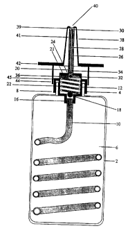
Figure 3 illustrates one form of the present invention comprising a reservoir
in the
form of a bottle 2 which is releasably engaged with a pump means 4 of a
syringe
type design. Within the reservoir there is a quantity of medicament 6, in
liquid
form, which is to be administered by the delivery device 8. The pump means 4
is
in communication with the reservoir 2 via a fine calibre tube 10 which
restricts the
flow rate of the medicament into the dose chamber 12. The fine calibre tube 10
releasably engages the base of the pumping means 4 by way of a connection
joint
16. Interposed in the base of the pump means 4 is a first one-way valve in the
form of a ball valve 18. The ball valve prevents the passage of fluid through
the
fine calibre tubing 10 when a positive pressure is applied to the dose
chamber.
Within the dose chamber there is a plunger 20 which is biased towards the top
of
the chamber 21 by a return spring 22. Extending perpendicular from the
plunger,
through an orifice 24 in the top of the chamber 21, is a plunger shaft 26.
CA 02224244 1997-12-OS
WO 96/40332 PCT/AU96/00345
_18_
Through the central axis of the plunger 20 and plunger shaft 26 is a conduit
28
which provides a means for venting the medicament from the dose chamber
when the plunger is depressed. The conduit 28 may also aid in atomising the
medicament prior to release from the delivery device. At the distal end of the
plunger shaft 30 the conduit 28 widens in diameter to facilitate dispersal of
the
medicament as it leaves the delivery device.
Interposed in the conduit is a controlling means 32 in the form of high
pressure
ball valve within an opening pressure of about 3000 mmHg. This valve prevents
the influx of air into the dose chamber when the pump draws medicament from
the reservoir and prevents the escape of fluid from the dose chamber when it
is
full. The valve comprises a seat and a ball above which is a spring which is
biased towards sealing of the ball with the seat. When the plunger is
depressed
pressure is created in the dose chamber. When the pressure in the chamber
exceeds the biasing force (eg 3000 mmHg) applied by the spring the valve
opens, providing a passage through which medicament may flow.
Around the peripheral edge of the orifice 24, in the top of the chamber 21,
there
is a fluid seal 34 in sliding arrangement with the walls of the plunger shaft
26.
The seal is capable of preventing the release of medicament and any vacuum
formed within the chamber.
Around the plunger there is a second fluid seal 36 in sliding arrangement with
the walls of the dose chamber. This seal is also capable of preventing the
release of the medicament and any vacuum formed within the chamber. Sealing
between the plunger and the chamber walls may be achieved using rubber or
plastic gaskets.
Seated over the plunger shaft 26 is a sheath 38 which provides protection for
the
shaft. At the distal end of the sheath 37 there is at least a orifice 40 which
allow
release of the medicament from the delivery device. The sheath 38 extends
down over the wall 41 of the plunger shaft and terminates above the top of the
pump housing 14 at a height equivalent to the distance that the plunger
travels
CA 02224244 1997-12-OS
WO 96/40332 PCT/AU96/00345
- 19-
downwards within the dose chamber when the plunger shaft is depressed. The
sheath 38 then extends perpendicular from the shaft for a distance slightly
greater than the horizontal width of the pump housing. The perpendicular
extension 42 provides a means by which an external force applied by a user of
the delivery device may be used to force the plunger shaft 26 downwards and
hence drive the plunger 20 downwards within the dose chamber 12.
Protruding from beneath the perpendicular extension 42 is at least one
projection 44. The projection 44 preferably envelopes part or all of the side
walls
of the pump housing 14 when the plunger is depressed. The projection may
also aid as an engaging means between the sheath 38 and the pump housing
14. In this instance the peripheral rim 45 on the top of the pump housing may
possess a flange (not shown) which engages an inverted flange (not shown) on
the inner surface of the bottom of the projection, when the plunger is
released.
In operation the user depresses the sheath 38 which in turn forces the plunger
20 downwards within the dose chamber 12 and creates a positive pressure
within the chamber. The positive pressure forces the valve in the base of the
pump housing to close and the controlling means 32 to open once a critical
pressure had been reached. Depression of the plunger 20 within the dose
chamber 12 causes a quantity of medicament 6 equal to the volume of the dose
chamber to pass through the conduit 28 and out through orifice 40, releasing
the
medicament. When the sheath 38 is released the spring 22 in the dose chamber
drives the plunger upwards towards the top of the dose chamber creating a
vacuum within the chamber. The vacuum opens the first one-way valve 18 in
the base of the pump and closes the controlling means 32 in the conduit 28
thereby enabling medicament to be drawn from the reservoir 2 through the fine
calibre tubing 10 into the dose chamber 12. The rate at which the plunger is
driven upwards towards the top of the dose chamber is determined by the rate
of
flow of medicament from the reservoir through the fine calibre tubing 10. The
overall infusion rate into the dose chamber is thus controlled by the volume
of
CA 02224244 1997-12-OS
WO 96/40332 PCT/AU96I00345
-20-
the dose chamber and the flow resistance of the tube 10 in relation to the
medicament.
The fine calibre tube 10 is preferably a plastics tube having a very narrow
bore
and a relatively thick wall, the latter ensuring that it does not kink in use.
Such a
tube and the method of producing it are described in published International
Patent Application W088/02637. The tube 10 preferably has a length in the
range 10 to 700 mm and a lumen diameter in the range 0.001 inch (0.025 mm)
to 0.008 inch (0.20 mm). In a particularly preferred form, the lumen diameter
is
0.070 mm and the tube length is about 30 to 60 mm.
The use of fine bore tubing not only sets the refill time of the dose chamber
12,
but also acts as a rate limiting factor in inhibiting over use of the delivery
device
by the patient. As an additional safety factor, the controlling means 32
located in
the conduit 28 should have an opening pressure greater than the maximum
possible hydrostatic pressure which is required to produce an appropriate
spray.
Figure 3(a) illustrates an alternative form of a one-way valve that may be
used in
the delivery device. Instead of a ball-valve the valve may consist of at least
two
pieces of elastomeric material 50 formed in an inverted cone, pyramid or V-
shape. When a vacuum is applied to the apex 52 of the valve mechanism the
elastomeric material separates creating an opening through which medicament
may flow. When a positive pressure is applied to the apex of the valve the
elastomeric material is forced together closing the passage way.
Figure 4 illustrates a series of medicament availability curves from a device
produced according to the present invention. The curves each represent
medicari~ent availability over a 5 minute delivery schedule. During the first
2'/i
minutes of filling of the delivery device there is insufficient liquid in the
dose
chamber to facilitate release of the medicament. After 3 minutes there is an
exponential increase in the availability of the medicament followed by a
gradual
peaking of medicament availability as the dose chamber becomes full. By
modifying the opening pressure of the controlling means and the return
pressure
CA 02224244 2006-09-06
-21 -
in the pump, it is possible to shift the availability of the medicament closer
towards
the optimum lockout time, (ie 5 minutes) in these graphs. The opening pressure
of the controlling means must be balanced against the patient's ability to use
the
device.
Figure 4a illustrates the filling and medicament availability curves for a
device
produced according to the present invention. Curve 1 illustrates the filling
rate of
the dose chamber of the device. Curve 2 illustrates the availability of
medicament. Curve 3 illustrates the effective absorption of medicament as it
is
released from the device. Initially filling of the dose chamber is rapid yet
relatively
inaccessible because of the influence of the high pressure controlling means.
As
the dose chamber begins to reach a substantially full state the amount of
medicament that may be released from the invention increases. However
because the dose chamber is not entirely full there is insufficient pressure
behind
the medicament to drive it through the second conduit to disperse it upon
release.
Thus most of the released medicament quickly coalesces as a liquid which in
the
case of a nasal spray is incapable of reaching the tissue surface where
absorption
takes place. Consequently medicament absorption is minimal. As the dose
chamber becomes completely full a spray may be generated when the device is
activated. This in turn is capable of saturating the surface area of the
tissue
surrounding the point of medicament administration which is reflected in a
rapid
rise in curve 3.
Figure 5 illustrates an alternative form of the medicament reservoir. In this
form
the medicament is contained within a collapsible sealed bag 60 which prevents
entry of air into the fine calibre tubing when properly filled. The bag
resides within
the reservoir 2 and is connected to the pump means 4 via a fine calibre tube
10.
The tube 10 is releasably engaged to the pump means 4 via a connection joint
16.
To assist in re-use of the bag 60 there is provided a refilling port 62, where
the
bag can be filled or emptied by means of a standard hypodermic syringe. The
CA 02224244 2006-09-06
-22-
bag also contains graduated markings 64 to indicate what volume of medicament
is within the bag.
Attached to the open end of the fine calibre tube within the bag is a spacer
66
which prevents the collapsible bag from covering the opening of the tube.
Figure 6 illustrates a second form of the medicament reservoir. In this form
the
reservoir is provided with a fill line 70 terminating in an injection site 72
which
allows priming of the fine calibre tubing 10 by means of a standard hypodermic
syringe. A hydrophilic filter (sponge) (not shown) may be included in the fine
calibre tubing or the fill line to prevent any air inadvertently introduced
into the
injection site 72 from reaching the reservoir 2.
Figure 7 illustrates a third form of the medicament reservoir. In this form
there is
provided between the reservoir 2 and the delivery device 8 a non-electronic
pump
system. In this embodiment the reservoir 2 is connected to a non-electronic
manually operable pumping mechanism such as an aspirating syringe 80 via fine
calibre tubing 10 which has a fine bore. In this embodiment the reservoir is
enclosed within a transparent plastic bag 81 for reasons of safety and
hygiene.
The return spring (not shown) of the aspirating syringe 80 is housed within a
cylindrical casing 84, the plunger 86 being actuated by a patient demand
button
88 extending from the casing. The syringe and the bag are linked by a cord 90
which allows the apparatus to be hung around the patient's neck for ambulatory
use.
An important preferred feature is the ability to remove the syringe (or
equivalent)
to assist in priming the system. The fine calibre tubing 10 has such an
extremely
fine bore that it is difficult to force liquid through it from the reservoir 2
to prime the
system. Accordingly to prime the system the aspiration syringe is removed from
the connector 92 and the patient line is filled with medicament, which may be
done by connecting a relatively large syringe at the connector and injecting
this to
overcome the resistance of the one way valve 94. The fine calibre tubing is
also
primed with liquid at this stage.
CA 02224244 1997-12-OS
WO 96/40332 PCT/AU96/00345
-23-
The aspirating syringe is then reapplied to the connector with the patient
demand button 88 held down. On release of the patient demand button 88, fluid
is drawn through the fine calibre tube 10 and is stored in the aspirating
syringe
80. When the patient demand button 88 is depressed medicament is forced out
of the syringe past the one way valve 94 and fills the delivery device line 96
within which there is interposed a non-elastic balloon 98. The balloon serves
as
a secondary reservoir from which the delivery device draws medicament.
Fine calibre tubing between the reservoir and the actuating syringe restricts
the
filling time of the syringe to the rate of flow of medicament through the
tubing.
Thus there is an induced time delay in the refilling of the syringe.
An important preferred feature is the provision of a one way valve 94 between
the actuating syringe 80 and the delivery device tubing 96 (illustrated as
being of
undefined length). Preferably this valve is activated under high pressure
only.
The pressure of actuation being equivalent to or slightly greater than the
pressure generated by a vacuum at sea level (ie, greater than 760 mm of
mercury). Thus the one way valve 94 serves as a lock out mechanism
preventing premature release of liquid in the actuating syringe until the
syringe is
full.
The delivery device line 96 is not formed of fine calibre tubing, but of
tubing of a
suitable diameter that does not substantially restrict the flow of liquid into
the
dose chamber. In this form the delivery device may be actuated in rapid
succession to deliver all of the medicament in the delivery device line 96 and
the non-elastic balloon 98. However once the medicament in the delivery device
line 96 and the non-elastic balloon 98 has been delivered, the patient is
unable
to obtain further medicament until the patent demand button 88 is depressed
thereby forcing medicament across the one way valve 94. Release of the
patient demand button causes the return spring within the cylindrical casing
to
return the plunger to rest position. This in turn creates a vacuum within the
syringe and draws medicament across the flow control tubing 10.
CA 02224244 1997-12-OS
WO 96/40332 PCT/AU96/00345
-24-
Figure 8 illustrates a fourth embodiment of the medicament reservoir. In this
form there is provided between the reservoir 2 and the delivery device 8 a
second reservoir 100.
The reservoir 2 is enclosed with a transparent plastic bag for reasons of
safety
and hygiene. In this embodiment the reservoir is connected to the second
reservoir 100 via flow control tubing 10 having a fine bore. Further the
plastic
bag containing the reservoir 102 is connected to a priming pin by a cord which
prevents accidental loss of the pin when it is separated from the second
reservoir 100.
Within the casing 104 of the second reservoir 100 there is a return spring 106
which is engaged to a plunger 108. The spring is also engaged to a first end
110 of the second reservoir. Passing centrally through the first end and the
casing is an adjustable stopping means 112 which defines the maximum
distance that the plunger 108 may be moved within the casing 104. Outside the
second reservoir 100 above the first end is an adjustment means 114 which
provides a system for adjusting the relative position of the stopping means
within
the second reservoir. The volume of liquid that may be drawn into the small
reservoir may be adjusted by altering the distance of the first end 116 of the
stopping means relative to the first end.
Passing centrally through the first end 110 and the stopping means 112 is a
separable priming pin 102 which extends from above the adjustment means 114
to the first end 116 of the stopping means. When the priming pin is inserted
into
the second reservoir the first end of the pin abuts the plunger 108. Priming
of
the second reservoir may be achieved by depressing the priming pin thereby
forcing the plunger towards the second end of the reservoir. This extends the
biasing means. When the priming pin is released the contractile pressure
created by the return spring draws the plunger 108 towards the first end 116
of
the stopping means thereby drawing medicament into the second reservoir.
CA 02224244 1997-12-OS
WO 96/40332 PCT/AU96/00345
-25-
An important feature is the ability to remove the second reservoir 100 to
assist in
priming the system. The control tubing 10 has such an extremely fine bore that
it is difficult to force liquid through it from the reservoir to prime the
system.
Accordingly, to prime the system the second reservoir is removed from the
connector and the delivery device tubing 118 is filled with medicament, which
may be done by connecting a relatively large syringe (not shown) at the
connector and injecting medicament into the delivery device tubing 118 as well
as the fine calibre tubing 10.
The second reservoir 100 is then reapplied to the connector while the priming
pin 102 is held down. On release of the priming pin, fluid is drawn through
the
fine calibre tubing and is stored in the second reservoir. After release of
the pin
it may be removed from the second reservoir. Fine calibre tubing 10 between
the reservoir 2 and the small reservoir 100 restricts the filling time of the
second
reservoir to the flow rate of medicament through the tubing.
An important aspect of this invention is the contractile tension of the return
spring 106 in the second reservoir 100. Preferably the spring is capable of
drawings of vacuum within the reservoir which is less than the vacuum drawn
within the dose chamber in the delivery device. For example, the second
reservoir 100 would be capable of generating a pressure of negative 400 mm Hg
(compared to atmosphere).
Upon actuation of the delivery device 8 medicament is released from the dose
chamber. The pump then draws a vacuum of greater than atmospheric pressure
which fills the dose chambers using medicament in the delivery device line.
Since the vacuum drawn by the delivery device is greater than that drawn by
the
second reservoir fluid will pass from the second reservoir into the delivery
device. Once the dose chamber in the delivery device is full no further vacuum
is drawn across the delivery device line. The second reservoir 100 continues
to
draw liquid through the small reservoir until the plunger 108 abuts the first
end of
the stopping means 116.
CA 02224244 1997-12-OS
WO 96/40332 PCT/AU96/00345
-26-
In this configuration a patient is able to rapidly deliver all of the
medicament
stored in the secondary reservoir but is prevented from drawing further
medicament from that reservoir until the second reservoir gains sufficient
fluid to
refill the delivery device. The rate of filling the second reservoir is
dictated by the
flow rate across the flow control tubing. Thus if a patient delivers all of
the
medicament in the second reservoir in a number of rapid doses they will be
locked out from obtaining additional medicament until there is sufficient
medicament in the second reservoir to refill and activate the delivery device.
Figure 9 illustrates an alternative embodiment of the present invention. In
this
form there is provided a secondary discharge control assembly attached to the
delivery device 8 and reservoir 2. The delivery device 8 comprises a modified
pump actuating means consisting of a lever 120 which is pivotally mounted to
the pump housing on a mount 122 . The lever engages the plunger shaft in a
manner which facilitates slidable engagement between the lever and the shaft
(not shown). When the lever is depressed it drives the shaft through the pump
housing thereby forcing actuation of the pumping assembly.
Releasably mounted to the distal end of the plunger shaft is a second dose
chamber 124. Located within the second dose chamber housing is a venting
system 126, a return line 128 and a release portal 130 within which is located
a
pressure activated controlling means 132. The release portal is connected to
an
intravenous delivery line which in turn is connected to a patient.
The venting system 126 is adapted to release any air trapped within the second
dose chamber and which may enter the chamber follow discharge of
medicament into said chamber
The return line 128 passes from the second dose chamber and is in fluid
communication with the reservoir 2 where it meets connection joint 16. Excess
medicament passing through the return line is thus recirculated into the
operational filling of the dose chamber 12.
CA 02224244 1997-12-OS
WO 96/40332 PCT/AU96/00345
_27_
The pressure activated controlling means 132 is in the form of a ball valve.
The
valve prevents the flow of medicament from the delivery line into the second
dose chamber. It also provides a means of restricting the passage of
medicament through the delivery line, at least, until sufficient pressure is
generated by the fluid entering the second dose chamber to open the valve.
Thus be selecting suitable valves to act as the pressure activated controlling
means it is possible to restrict the passage of fluid entering the delivery
line to
that which has come from a full dose chamber.
Upon activation of the pumping assembly, medicament is forced into the second
dose chamber 124 via the conduit 28. If the pressure generated by medicament
entering the second dose chamber is sufficient to open the pressure activated
controlling means 132 it will enter the delivery and pass via an air filter
134 to a
patient. If however, there is insufficient pressure behind the medicament
delivered to the second dose chamber the pressure activated controlling means
will remain closed and no liquid will enter the delivery line. Excess liquid
retained in the second dose chamber may be returned to the reservoir 2 via the
return line 128.
The invention thus provides a patient-controlled apparatus which is of simple
and inexpensive construction and has a high level of inherent safety. The
apparatus is extremely simple to operate. Owing to its simplicity and
cheapness
it can be used as a disposable item. The apparatus can be manufactured for
use with a particular medicament by suitable choice of delivery device and
bore
of the fine calibre tube; on-site adjustment is then not required, and the
apparatus can be used by a patient without specialist training.