Note: Descriptions are shown in the official language in which they were submitted.
CA 022246~7 1997-12-12
W O 96/41981 ~ _ PCT/GB96/01405
FLUID FLOW C~..l-~L VALVE
This invention relates to a fluid flow control
valve and, in preferred aspects, to a fluid flow
control valve in combination with an immobilising
system for a motor vehicle, and to a method of
protecting against theft a vehicle powered by an
internal combustion engine.
It is known to provide a motor vehicle powered by
an internal combustion engine with a fuel flow shut-off
valve, whereby operation of the engine is inhibited
until the valve has been opened. In an attempt to make
it significantly more difficult for an unauthorised
person to start the engine of the vehicle, there have
been proposals to fit such a valve with a key-operated
mechanism, whereby opening and closing of the valve may
be achieved only by use of an appropriate key for the
mechanism. Though in principle this will increase the
security against theft of the vehicle, it does have the
disadvantage that a driver of the vehicle has to insert
the key into the lock mechanism and operate that
mechar.ism to close the valve, when the vehicle is to be
left for any significant period of time. Though it may
be simple and take only a relatively short time to
effect closing of the valve with a key, experience
shows that people are reluctant to undertake this extra
step on leaving a vehicle, and so the vehicle often
will not benefit from having a security fuel flow shut-
off valve fitted to the engine.
In an attempt to overcome the above disadvantage
associated with the use of the known kind of fuel flow
shut-off valve fitted with a key-operated lock
mechanism, the present invention provides a fluid flow
control valve including a fluid passage in which is
provided valve seat, a valve member and a spring urging
-
CA 022246~7 1997-12-12
WO 96/41981 - 2 - PCT/GB96/01405
the valve member to a closed position where the valve
member seals against the valve seat, the valve further
comprising a key-actuated setting mechanism arranged
upon operation with a key to move the valve member away
from the closed position to an open position, latch
means to restrain the valve member in the open position
when moved there by the setting mechanism, and
electrically-operable release means for the latch means
whereby operation of the release means frees the valve
member to move under the action of the spring from the
open position to the closed position.
Though it will be appreciated that the fluid flow
control valve of the present invention may be used in a
variety of situations where a security fluid flow valve
may be required, the valve is particularly suitable for
use as a fuel flow shut-off valve for an internal
combustion engine. The engine may be installed in a
motor vehicle, such as a car, truck or lorry; equally,
the engine could be installed to power a boat or
aeroplane. The term "vehicle" as used herein should
thus be interpreted broadly, to cover all of these
possible internal combustion engine powered modes of
transport.
With the fluid flow control valve of the present
invention, once the valve has been closed by the
electrically-operable release means, a key has to be
used to cause actuation of the setting mechanism if
fluid flow is required once more. In the case of the
valve being installed to control the fuel flow to an
internal combustion engine of a vehicle, the valve may
be opened only by use of the key whenever the engine is
to be operated, following closing of the valve by the
release means. It is therefore preferred for the
electrically-operable release means to be connected to
the electric circuits associated with the vehicle in
which the engine is installed so that closing of the
CA 022246~7 1997-12-12
W O 96/41981 _ 3 _ PCT/GB96/01405
valve is performed automatically, whenever at least one
pre-determined electrical system of the vehicle is
turned off. In this way, the valve may be arranged to
ensure a driver of the vehicle cannot prevent closing
of the valve on leaving the vehicle,= and the driver and
must take positive action with the appropriate key,
whenever the vehicle is thereafter to be started.
In one particular embodiment of the fluid flow
control valve of this invention, the valve member is in
the form of a spool arranged for linear sliding
movement towards and away from the valve seat. In this
case, the latch means may comprise a plunger mounted
for movement in a direction substantially per-
pendicular to the line of movement of the valve member,
the plunger being engageable with the valve member to
hold the valve member in its position where the valve
is open. Preferably, the plunger is spring-urged to a
position where the plunger is engaged with the valve
member, and the release means comprises a solenoid
arranged to act on the plunger, to move the plunger
against the spring bias, so freeing the valve member to
move under its spring bias to its position where the
valve is closed.
The setting mechanism may be purely mechanical,
and take the form of a key-operated lock mechanism
connected to the valve member. Alternatively, the
setting mechanism may be electrically operated, for
example having a solenoid which is arranged, when
energised, to cause movement of the valve member to its
open position. In such a case, the supply of
electrical energy to the setting mechanism may be under
~ the control of a key-operated switch, so that the
operator has to use the key to open the valve. Another
possibility is for the supply of electrical energy to
be under the control of a vehicle immobiliser system,
which system may be operated only with the use of an
CA 022246~7 1997-12-12
W O 96i41981 ~ _ 4 _ PCT/GB96/01405
appropriate key. Such a key may be a conventional
mechanical key which may be inserted into a lock, or
could be in the form of a card or other data carrier
which may be read electronically by the immobiliser
system. A so-called l'smart cardll is particularly
suitable for this purpose, where the card carries an
integrated circuit pre-programmed with information.
For the case of a mechanical key-operated lock
mechanism, the key may be restrained against withdrawal
from the mechanism other than when the mechanism is at
a first position, and movement of the mechanism from
the first position to a second position serving to open
the valve. As the valve member is then latched at the
second position, the lock mechanism may be returned to
its first position to permit withdrawal of the key. By
closely associating the key for the lock mechanism with
the llignitionll key for operation of the engine, for
example by mounting both keys on the same key ring,
before the engine can be started, the operator has to
turn the lock mechanism back to its first position to
withdraw the key. This ensures that the valve member
can move to its position where the valve is closed when
next the electrical release means is operated; in turn
this ensures that a key must be used to open the valve,
the next time the engine is to be started.
The fluid flow control valve may include
electrical contact means arranged to detect manual
opening of the valve. Such contact means may be
connected to an external circuit, such as an
immobilising system of a motor vehicle, to control the
operation thereof. In addition, there may be provided
further contact means to detect return of the key to
the first position or the removal of the key, following
opening of the valve with the key.
This invention extends to a fluid flow control
valve of this invention as described above, in
CA 022246~7 1997-12-12
W O 96/41981 5 PCT/GB96/01405
combination with an immobilising system for a motor
vehicle, the immobilising system being disarmed by the
contact means detecting opening of the valve by use of
the key, then to permit operation of a vehicle to which
the valve and immobilising system is connected
In the case of such a combination, the
electrically-operated release means preferably is
powered to release the latch means by an activity
associated with a driver leaving the vehicle. For
example, that activity may be one or more of turning
off the ignition supply to the engine, closing all of
the doors of the vehicle with the engine already turned
off within some preset period beforehand, and locking
the doors of the vehicle.
This invention extends to a method of protecting
against theft a vehicle powered by an internal
combustion engine, comprising installing in the fuel
line to the engine a fluid flow control valve having
open and closed positions, the fluid flow control valve
having a key-operated setting mechanism for opening of
the valve and electrical release means to close the
valve, and connecting the electrical release means to
the vehicle electrical systems so as to be energised
automatically upon the vehicle being left unattended.
Preferably, a vehicle electrical immobilising system is
connected to the electrical circuits of the vehicle and
is also arranged to detect opening of the valve by use
of the key, so as then to allow operation of the
vehicle.
By way of example only, two specific embodiments
of fluid flow control valve constructed and arranged in
accordance with the present invention and intended for
use in association with a vehicle immobilising system,
to control operation of both the vehicle and its
engine, will now be described in detail, reference
being made to the accompanying drawings, in which:-
CA 022246~7 1997-12-12
W O 96/41981 6 PCT/GB96/01405
Figure 1 is a diagrammatic, part--sectional view
through the valve;
Figure 2 is a diagrammatic, part--sectional view
through the valve of Figure 1 and taken on arrow A
marked on Figure 1;
Figures 3 and 4 diagrammatically show the
important component parts of the valve of Figures 1 and
2, when respectively closed and opened; and
Figure 5 diagrammatically shows a second
embodiment of fluid flow control valve of this
invention and having an electrical setting mechanism.
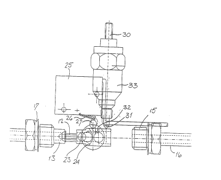
Referring initially to Figures 1 and 2, the fluid
flow control valve comprises a main body 10 in which
there is defined a fuel flow passageway 11, a valve
member 12 being slidably mounted in the passageway 11
and co--operating with a valve seat 13 threaded into a
counterbore at one end of the passageway 11. Spring 14
acts between the valve member 12 and union 15 threaded
into the opposite end of the passageway 11, so as
thereby to bias valve member 12 into engagement with
the valve seat 13. Union 15 serves to connect an inlet
fuel pipe 16 to the main body 10, and valve seat 13 is
formed as part of a union 17 which serves to connect a
fuel outlet pipe 18 to the main body 10.
A security lock mechanism 20 is mounted within the
main body 10 and is operable by means of a key 21
unique to that lock mechanism 20. The lock mechanism
20 is drivingly coupled to a camshaft 22 having an
eccentric peg 23 at its end remote from the lock
mechanism 20. That peg 23 lies within the passageway
11 and is engageable with an arcuate surface 24 formed
on the valve member 12. Figure 3 shows the peg at its
initial position with the valve member closing the
valve seat 13. Rotation of the lock mechanism 20 by
means of the key 21 turns the camshaft 22 in the
clockwise sense, so moving peg 23 to the right. This
CA 022246~7 l997-l2-l2
W 096/41981 _ 7 _ PCT/GB96/01405
acts on arcuate surface 24 of the valve member and so
moves the valve member to the right, opening the valve.
A microswitch 25 iS mounted within the main body
10 and has an operating lever 26 provided with a cam
follower 27 resting on the camshaft 22. The camshaft
has a cam profile which interacts with the cam follower
27, thereby to actuate the microswitch 25. The
arrangement is such that the contacts of the
microswitch are closed when the lock mechanism is in
its initial position, as illustrated in Figure 3.
A latch mechanism is provided to hold the valve
member 12 in its valve--open position, that latch
mechanism including a plunger 30 mounted for movement
radially of the passageway 11 and spring-urged to a
position where the free end 31 of the plunger projects
into the passageway. The valve member 12 has an
annular recess 32 into which the free end 31 of the
plunger may locate, when the valve member 12 iS lifted
off the valve seat 13.
A solenoid 33 is located in a bore in the main
body 10, the plunger 30 extending through the solenoid.
Energisation of the solenoid pulls the plunger out of
the passageway 11, so freeing the valve member 12 to
move under the influence of spring 14 back to the
initial position where the valve seat 13 is closed.
The fluid flow control valve described above is
intended to be fitted in the fuel line to an internal
combustion engine installed within a vehicle, which
also is fitted with a vehicle immobilising system. The
microswitch 25 is arranged to supply an input to the
immobilising system and the solenoid 33 iS controlled
by that immobilising system.
When the immobilising system is fully armed, the
solenoid 33 iS briefly energised in order to lift the
plunger 30 and so free the valve member 12 to close the
valve seat 13. Fuel cannot then be supplied to the
- CA 022246~7 1997-12-12
WO 96/41981 8 PCT/GB96/01405
engine. When the engine is to be operated, a key 21
must be used to operate the lock mechanism 20, manually
to lift the valve member 12 away from valve seat 13.
The valve member 12 is latched in that lifted position
5 by the free end 31 of the plunger 30 engaging in the
annular groove 32. Turning the key back to the initial
position will close the contacts of the microswitch 25.
This closing action is detected by the immobilising
system, which then disarms those circuits of the
10 vehicle rendered inactive by the armed immobilising
system. Thereafter, the engine may be started and the
vehicle driven in the usual way.
The immobilising system should operate on at least
two separate electrical circuits of the motor vehicle.
15 For example, when armed, the immobilising system may
protect both the starter motor circuit and the ignition
circuit. Those circuits are rendered active once more
when the key is used to open the valve.
The immobilising system should provide the
20 required pulse to the solenoid 33 to lift the plunger
30 following the detection of certain pre--defined
activities associated with the driver leaving the
vehicle. For example, the pulse may be provided when
the doors are locked some preset period after the
25 engine has been turned off.
Figure 5 shows a second embodiment of fuel flow
control valve of this invention, which uses an
electrically operated setting mechanism indirectly
controlled by a key. The valve comprises a valve body
30 35 in which is formed a fuel flow passage 36 and
defining a valve seat 37 against which a valve member
38 may seal in order to close the valve. The valve
member 38 is arranged for linear sliding movement with
respect to the valve body 35 and is provided with a
35 resilient valve face 39 for sealing against the seat
37. An annular groove 40 is formed around the valve
CA 022246~7 1997-12-12
W O 96/41981 9 PCT/GB96/0140S
member 38 adjacent the valve face 39 and a latching
mechanism includes a peg 41 spring--loaded to engage in
that groove, as shown in Figure 5. The latching
mechanism has a release solenoid 42 which when
energised withdraws the peg 41 from the groove 40, so
freeing the valve member 38 to move to the left (in
Figure 5) under the action of a compression spring (not
shown).
A setting solenoid 43 is arranged around the axis
10 of movement of the valve member 38 and when energised,
withdraws the valve member from a position where face
39 seals on the valve seat 37 to the position
illustrated in Figure 5 so permitting peg 41 to latch
the valve member at the open position when solenoid
15 43 is de--energised again. A further groove 44 is
formed in the valve member and provides a shoulder
against which the peg 41 may engage when the valve
member is in its closed position. This serves to
prevent the valve member being moved to its open
20 position when setting solenoid 43 is energised unless
release solenoid 42 is also energised to withdraw peg
41.
The supply of energy to the two solenoids 42 and
43 is under the control of an immobiliser shown
25 diagrammatically at 45. This immobiliser includes a
data card reader into which a data card 46, serving as
a key for the immobiliser, may be inserted. Unless
such a key is inserted and the appropriate security
codes entered in a manner known per se, the immobiliser
30 will maintain immobilised a vehicle to which the fuel
valve and immobiliser are fitted. Provided a key is
inserted and the entered codes are recognised by the
immobiliser, the immobiliser energises solenoids 42 and
43, to move the valve member 38 to the open position
35 shown in Figure 5.
CA 022246~7 1997-12-12
WO 96/41981 PCT/GB96/01405
-- 10 -
The valve is provided with suitable sensors (not
shown) so that a signal may be provided to the
immobiliser indicative of the state of the valve.
Then, in other respects the immobiliser may interface
with the valve and the electrical systems of the motor
vehicle as has been described above with reference to
the first embodiment. Operation thus corresponds to
that which has previously been described and will not
~ be described again here.
It will be appreciated that both embodiments
employ passive arming but manual key-operated dis-
arming. Enhanced security is in this way assured. An
operator cannot fail to arm the system on leaving the
vehicle, which is then protected by the fuel shut-off
valve as well as the disabling of two separate
electrical circuits. The key-operated setting
mechanism requires the use of a security key to open
the fuel valve and so should someone try to overcome
the disabling of the electrical systems, the vehicle
still cannot be driven.
.
.. . . ..