Note: Descriptions are shown in the official language in which they were submitted.
' CA 02224837 1998-01-23
LIFT TRUCK
BACKGROUND OF THE INVENTION
The invention relates to lift trucks also known as forklift trucks
used for manoeuvring loads such as crates of goods and the like.
More particularly, the invention relates to such trucks adapted for use
in narrow aisle warehouses which trucks are highly manoeuvrable.
i
A known truck of this type is disclosed in WO91/01938 which
describes a narrow aisle lift truck having a pair of rear drive wheels
and a forward pair of wheels fixedly attached to a lifting device
comprising a mast, lifting mechanism and lifting forks. The lifting
device is pivotally connected to the main body of the truck such that
rotational movement of the lifting device about the pivot axis acts
both to steer the direction of movement of the vehicle and any goods
held by the forks. In order to provide increased manoeuvrability,
WO91/01938 provides reversible independent drives to each of the
rear wheels.
An object of the invention is to provide greater performance
than that known from prior art trucks and especially to provide greater
manoeuvrability in narrow aisles. A further object of the invention
is to provide a truck capable of handling long loads in narrow aisle
warehouses.
CA 02224837 1998-01-23
SUMMARY OF THE INVENTION
According to one aspect of the invention there is provided a lift
truck for lifting crates of goods and the like comprising a body having
ground engaging means, a lifting device having a mast and means for
lifting goods with respect to the mast which lifting device is pivotally
attached to the body about a first axis, at least one steerable wheel
proximal the lifting device which wheel is pivotable about a second
axis to enable steering of the truck, and means for independently
pivoting the lifting device about the first axis and the steerable wheel
about the second axis. Beneficially therefore the direction of
movement of a truck can be determined by the steerable wheel and/or
lifting device and the goods can be handled and directed in a different
direction to the movement of the truck. Additionally, increased
manoeuvrability is provided.
Preferably the second axis is positioned further from the truck
body than the first axis and more preferably the steerable wheel is
below the lifting means thereby to provide good stability of the truck
n use.
In one form, the steerable wheel is pivotably attached to the
lifting device and in another form the steerable wheel is pivotably
attached to the body and therefore entirely independent of the lifting
device.
CA 02224837 1998-01-23
Preferably the truck comprises two steerable wheels which are
axially separated along a common rotational axis. In one form, the
two steerable wheels are connected to the truck at a common pivot
providing the second axis. Preferably the second axis is disposed
between the wheels. In another form, the truck comprises two
steerable wheels each being pivotal about independent second axes.
Accordingly, each steerable wheel is attached to the truck, at either
the body or the lifting device, at a separate point.
According to another aspect of the invention a lift truck of the
generally known type is provided wherein the body is adapted to
allow a load operably to be positioned over part of the body thereby
enabling the centre of gravity of the load to be kept close to the
centre of gravity of the truck. Beneficially, the lifting device is
adapted to position the load to one side of the body whilst still
allowing the truck to move in a forward and other directions.
Therefore, a long load can be positioned on the lifting device and
preferably can also be supported by part of the truck body. For
example, a body part above rear drive wheels can be kept low and a
support means provided for the load in the vicinity of the body part.
Embodiments of the invention will now be described, by way
of example only, with reference to the accompanying drawings.
CA 02224837 1998-01-23
BRIEF DESCRIPTION OF THE DRAWINGS
FIGURE 1 is a plan view of a truck according to the invention;
FIGURE 2 is a side elevation view of the truck shown in
Figure l;
FIGURE 3 is a plan view of the truck shown in Figures 1 and
2 at four different stages of manoeuvring a load into a space;
FIGURE 4 is a rear elevation view of the truck shown in
Figure 1 having a load positioned to the side of the vehicle;
FIGURE 5 is a plan view of the truck shown in Figure 4 during
two stages of manoeuvring a long load;
FIGURE 6 is a partial plan view of a second embodiment of a
truck according to the invention;
FIGURE 7 is a partial plan view of a third embodiment of a
truck according to the invention; and
FIGURE 8 is a plan view of the invention showing in particular
details of the drive mechanisms.
' CA 02224837 1998-01-23
DESCRIPTION OF THE PREFERRED EMBODIMENTS
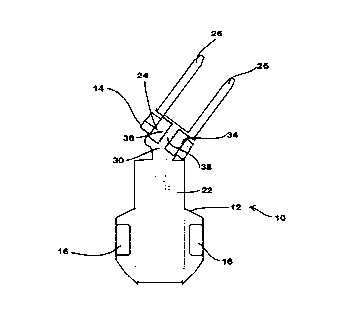
Referring to Figures 1 and 2, there is shown a truck 10
according to the invention comprising a body 12 and lifting device 14.
Body 12 comprises a pair of rear wheels 16, a cabin 18 housing a seat
20 and steering and lifting controls 22 and 22a. The lifting device 14
comprises a mast 24, forks 26 and a mech~ni~m 28 for raising and
lowering of the forks on the mast. The lifting mechanism 28 can
comprise hydraulic and/or chain and sprocket mechanisms for
example. Lifting device 14 is pivotably attached to body 12 at a
pivot hinge or bearing 30 having a pivot axis 32.
Truck 10 further comprises front steerable wheels 34 rotatable
about a common horizontal axis 36. The steerable wheels are
pivotally attached by a pivot 38 having a pivot axis 40 to a plate 42.
Plate 42 is in turn connected, in this embodiment, to lifting device 14.
In this configuration, axes 40 and 32 are alignable along the
longit~ldin~l axis of the truck 10, with axis 40 furthest from the body
12, and beneath device 14.
Independent mechanisms (described later in relation to Figure
8) are provided for effecting rotation of the lifting device 14 about
axis 32 and for rotating steerable wheels 34 about axis 40.
Additionally, a drive system such as a combustion engine is provided
in body 12 for driving any one of wheels 16 and 34. Preferably,
' CA 02224837 1998-01-23
means is provided for driving any wheel in a forward or reverse
direction.
Figure 3 shows four different plan views of a procedure of
placing a load L into a storage bay using truck 10. As can be seen
from Figure 3a, truck 10 can be used with axes 40 and 32
substantially in line along the longitudinal axis of the truck to drive
load L in a forward (or reverse) direction. To manoeuvre the load L
into a storage bay (or other predetermined position) lifting device 14,
and accordingly forks 26 and load L, are rotated about axis 30. The
angle of movement of the truck and the load L can also be adjusted
by rotation of steerable wheels 34 about axis 40. By suitable
manoeuvring of steerable wheels 34 and lifting device 14, it is
possible to maintain the truck body 10 substantially at right angles to
the direction of movement of load L. Accordingly, truck 10 enables
the positioning of loads L in narrow aisles.
A rear view elevation of truck 10 is shown in Figure 4 where
a long load L is supported on forks 26. As can be seen in Figure 4,
in this version cabin 18 is relatively narrow compared to the width of
the body 12. Shoulder panels 44 are provided above wheels 16 and
it is possible to carry a load L in a relatively low position wherein
part of the load passes over a shoulder portion 44 of body 10 on one
side of the truck. Indeed, it is possible, as shown in Figure 4 for load
L to abut the shoulder 44. Shoulder 44 can be provided with internal
supports for increased load handling. Beneficially therefore, whilst
' CA 02224837 1998-01-23
the centre of gravity of a long load should be positioned between
forks 26, it is possible to carry some of the load on shoulder 44.
Moreover, it is possible to keep the centre of gravity of the load close
to truck 10 thereby to increase stability of the truck in use. Figure S
shows the benefit of manoeuvrability of truck 10 in handling a long
load L. Lifting device 14 is positioned at right angles to the
longitllclin~l axis of the truck. This causes pivot 38 to be displaced
to one side of the truck as shown in Figure Sa. However, the
independent steering mechanism to steer wheels 34 enables the truck
to continue in a forward direction. Additionally, the load can be
manoeuvred sideways into an appropriate bay through suitable
rotation by a driver of the steerable wheels and lifting device about
axes 40 and 32 respectively.
A further embodiment of the invention is shown in Figure 6
wherein a pair of steerable wheels 134a and 134b is provided each
having an independent rotation axes 136a and 136b respectively.
Additionally, each steerable wheel 134a and 134b has a separate pivot
138a and 138b respectively and first axis about which it can be
steered. In the embodiment shown in Figure 6 the pivots 138a and
138b are attached to lifting device 114. Beneficially the axial
separation of steer wheels 134a and 134b along axis 136 provides
greater lateral stability of a truck 100.
A further embodiment is shown in Figure 7 wherein wheels
234a and b each comprise separate pivots 238a and b respectively.
' CA 02224837 1998-01-23
'
The pivots are attached to body 212 independent of lifting device 214.
Referring to Figure 8, the independent drive means are shown.
The complete assembly (i.e. the lifting device 14) is steered by
rotating motor 64, which in turn drives steer chain 62. Steer wheels
34 are steered by rotating motor 63, which in turn drives steer chain
65.
The motor could be hydraulic or electrically controlled. Power
from the steering wheel 22 can be directed to either motor 63 or 64.
Both motors steer the truck, however with motor 64 the whole
assembly (14) turns (i.e. the mast, forks and steer wheels).
For example a switch can be provided such as a lever to change
control by the steering wheel to either motor 63 or 64. However, a
separate steering wheel can be provided to drive motor 63 and
accordingly a driver can, with practise, steer the truck using both
steering wheels at the same time.
When steering motor 63 is powered then only the steered
wheels 34 turn, leaving the forks stationary. This increases
manoeuvrability dramatically. The lifting mechanism 14 is mounted
above the steer wheels 34 and consists of a conventional telescopic
construction. It could be fed hydraulically and is fixed above plate
66. To turn the forks together with the lifting mechanism 14, motor
64 is powered by operating the steering 22 through that particular
circuit. The forks are normally powered up and down by hydraulic
pressure operated by a separate hand control lever 22a.