Note: Descriptions are shown in the official language in which they were submitted.
CA 02224838 1997-12-12
1
Apparatus for Processing Sheet-Like Products
Background of the Invention
The present invention relates to an apparatus for processing sheet-like
products, in particular printed products.
An apparatus of this type is disclosed in U.S. Patent Application Serial
No. 08/741,259 (corresponding to EP-A-0 771 754), commonly assigned with
the present application. It has a main conveyor that leads past a plurality of
feed locations and has a circulating drawing member, on which elongated
receiving elements are spaced apart one behind the other. These receiving
elements are positioned obliquely with respect to their movement path. The
circulatory path of each feed conveyor runs horizontally, in a rectilinear
manner, over the main conveyor and past the feed locations. Each feed
conveyor has individually controllable clamps that are spaced apart one
behind the other on a circulating chain and are intended for transporting
sheet-like products in a suspended state. When the clamps are open, the
sheet-like products are transferred to the receiving elements of the main
conveyor at the feed locations. The circulatory paths run in vertical planes
that are perpendicular to the longitudinal direction of the receiving
elements.
The clamps are arranged perpendicular to the circulatory path, and thus
parallel to the receiving elements. As a result, the products are fed to the
receiving elements from the side.
It is an object of the present invention to provide an apparatus for
processing sheet-like products, in particular printed products, that, while
handling the products carefully, permits a high degree of flexibility in the
arrangement and design of the main conveyor and the feed conveyors.
1
CA 02224838 1997-12-12
2
Summary of The Invention
The present invention provides an apparatus for processing sheet-like
products comprising at least one main conveyor that runs past a feed
location. The main conveyor has an elongate receiving element to which a
product can be fed at the feed location, and the receiving element defines a
receiving-element plane for the product.
The apparatus of the present invention also comprises a feed conveyor
with a plurality of individually controllable clamps that are arranged one
behind the other. Each clamp has a clamp mouth defining a clamp-mouth
plane. The clamps are moved in a feed direction along a continuous
circulatory path running past the feed location to convey products up to the
feed location and to discharge products at the feed location to the receiving
element. The circulatory path has a selection arranged directly upstream of
the feed location.
In the apparatus of the present invention, the clamps are arranged at
the feed location and in the section of the circulatory path obliquely with
respect to the circulatory path. As a result, the angle that is formed by the
circulatory path and a straight line running parallel to the clamp-mouth
plane,
perpendicular to a longitudinal direction of the clamp mouth, and at least
approximately parallel to the receiving-element plane, is respectively acute
or
obtuse.
Brief Description of the Drawings
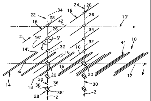
Figure 1 shows a plan view of a rectilinear section of a preferred
embodiment of a main conveyor of the apparatus of the present invention,
with obliquely positioned receiving elements. Also shown are two feed
conveyors of the present invention with obliquely positioned transporting
clamps. At feed locations, the feed conveyors run over the main conveyor
perpendicular to the conveying direction of the main conveyor as shown.
2
CA 02224838 1997-12-12
3
Figure 2 shows a clamp of a feed conveyor shown in Figure 1, in the
direction of the arrow II.
Figure 3 shows a plan view of a further embodiment of the apparatus
of the present invention. In this embodiment, the movement path of the
receiving elements of the main conveyor and the circulatory paths of the
clamps of the feed conveyors run in the same manner as in the embodiment
shown in Figure 1, although the acute angle formed by the receiving elements
and their movement path is larger and the acute angle formed by the clamps
and their circulatory paths is smaller.
Figure 4 shows a plan view of an embodiment of the apparatus of the
present invention, in which the receiving elements of the main conveyor are
arranged perpendicular to their movement path and, at feed locations, two
feed conveyors run obliquely over the main conveyor with their clamps being
directed parallel to the receiving elements.
Figure 5 shows a plan view of a further embodiment of the apparatus
of the present invention, in which the receiving elements of the main conveyor
run perpendicular to their movement path and the feed conveyors run over
the main conveyor at an acute angle that is larger than in the embodiment
shown in Figure 4.
Figure 6 shows in plan view an embodiment of the apparatus of the
present invention having a receiving element that ends in the conveying
direction of the main conveyor, and two feed-conveyor circulatory paths that,
at feed locations, run over the receiving element with their clamps being
aligned parallel to the receiving element.
Figure 7 shows a plan view of an embodiment of the apparatus of the
present invention having a plurality of parallel receiving elements that run
in
the conveying direction F of the main conveyor and are arranged so as to
circulate around a common axis of rotation. This embodiment also has three
feed conveyors that run obliquely over the axis of rotation and have clamps
arranged parallel to the receiving elements.
3
CA 02224838 1997-12-12
4
Figure 8 shows a perspective view of a rectilinear section of a main
conveyor of the apparatus of the present invention with L-shaped receiving
elements and two feed conveyors that slope toward the feed locations and
have clamps arranged obliquely with respect to their circulatory path.
Figure 9 shows a plan view of the embodiment of the rectilinear section
shown in Figure 8.
Figure 10 shows a view of a region of a feed conveyor of the apparatus
of the present invention with obliquely positioned clamps receiving products
that are fed by a belt conveyor.
Figure 11 shows a side view, in the direction of the arrow XI of Figure
10, of those regions of the feed conveyor and of the belt conveyor that are
shown in Figure 10.
Detailed Description
Figure 1 shows, in plan view, a simplified illustration of a region of a
main conveyor 10 of a preferred embodiment of the present invention. The
main conveyor 10 has a movement path 12 that is indicated by chain-dotted
lines and is rectilinear in the region. Receiving elements 14 are driven
continuously in circulation along the movement path 12, and are spaced apart
one behind the other by a fixed distance in the conveying direction F. As
shown in Figure 1, the elongate receiving elements 14 are positioned
obliquely with respect to the conveying direction F and form an acute angle a
with the conveying direction F. As a result of this oblique positioning, one
edge 14' of the receiving element 14 leads the other, as seen in the
conveying direction F. For the purpose of collecting, collating or inserting
products 16, the receiving elements 14 may be designed in a pocket-like
manner or, as best shown in Figure 8, in an L-shaped manner. It is also
possible, however, for the purpose of collecting the products 16, to design
the
receiving elements 14 in a saddle-like manner. The receiving elements 14
establish a receiving-element plane 18 which, in the case of the receiving
4
.. CA 02224838 1997-12-12
elements 14 being designed in a pocket-like or L-shaped manner, is defined
by that wall against which the products 16 that have been fed to the receiving
element 14 come to rest. In the case of the receiving elements 14 being
designed in a saddle-like manner, the receiving-element plane is defined by
5 the center plane running in the longitudinal direction.
The movement path 12 of the main conveyor 10 runs past two feed
locations 20 that are spaced apart from one another in the conveying
direction F. A feed conveyor 22 or 24 likewise runs past each of the feed
locations 20. Each of the feed conveyors has clamps 28 that are spaced
apart one behind the other at a fixed distance on a continuously driven,
endless drawing member 26. The clamps 28 have a circulatory path 30 with
a circulatory-path section 32 that is arranged directly upstream of the feed
location in the feed direction Z. At the feed location 20, the circulatory
path
30 runs above the main conveyor 10 and in a vertical plane 34 that is
perpendicular to the conveying direction F. The distance between the main
conveyor 10 and the feed conveyors 22, 24 at the transfer locations 20 is
small, Preferably, it is smaller than the length, as measured in the vertical
direction, of the products 16 that are to be fed in the suspended state by the
clamps 28.
Figure 2 shows one of the clamps 28 as seen in the direction of arrow
II in Figure 1. It has two clamping jaws 38, 38' that are arranged on a
carrying element 36 which is connected to the drawing member 26. The
clamping jaws can be moved from an open position into a closed position
(shown in Figure 2) and vice versa. The open position is indicated in Figure 1
by the clamps 28 that are located at the transfer locations 20 and downstream
thereof in the feed direction Z. The clamping jaws 38, 38' form a clamp mouth
40, the longitudinal direction of which is designated by the double arrow L.
In
the closed position of the clamping jaws 38, 38', the clamp mouth 40 defines
a clamp-mouth plane 40'. The part of a product 16 that is retained by the
clamp 28 and arranged in the clamp mouth 40 is located essentially in this
5
CA 02224838 1997-12-12
6
clamp-mouth plane 40'. Reference numeral 42 designates a straight line that
runs parallel to the clamp-mouth plane 40' and perpendicular to the
longitudinal direction L.
As shown in Figure 1, the clamps 28 are positioned obliquely with
respect to their circulatory path 30, such that the straight line 42 and the
circulatory path 30 form an acute angle ~i and an obtuse angle ~3' that is
supplementary to the acute angle. Furthermore, the straight line 42 runs
parallel to the receiving-element plane 18.
The distances between the receiving elements 14 and clamps 28, and
the conveying speed of the main conveyor 10 and the feed rate of the feed
conveyors 22, 24, are co-ordinated with one another such that a product 16 is
introduced by each feed conveyor 22, 24 into each receiving element 14 from
the side, in the manner of intermeshing, obliquely toothed racks. The product
16 is transferred as it passes the feed location 20 by virtue of the clamps 28
being opened. As ,a result, the individually fed products 16 are combined in
the receiving elements 14 to form intermediate products or main products 44,
which are removed from the receiving elements 14 downstream of the feed
locations 20 for the purpose of further processing.
In order to ensure optimum introduction of the products 16 into the
receiving elements 14 by the feed conveyors 22, 24, and optimum
introduction of the forces acting on the products 16 (as the direction of the
products changes after the clamps 28 have been opened), the feed direction
Z is advantageously directed with respect to the conveying direction F. The
leading edge 14' of the receiving elements 14 and the leading edge 16' of the
products 16, with respect to the feed direction Z, are directed toward one
another. The leading edge 16' of the products 16 follows behind with respect
to the conveying direction F, the opposing trailing edge of the products 16.
For the sake of completeness, it should be mentioned that the
circulatory-path section 32 may run horizontally or may slope in the feed
direction Z.
6
CA 02224838 1997-12-12
7
The chain-dotted line designated by 10' in Figure 1 indicates a second
main conveyor, which runs parallel to and is of the same design as the main
conveyor 10. The points at which the feed conveyors 22, 24 intersect the
second main conveyor 10' likewise form feed locations at which the feed
conveyors 22, 24 can each discharge one product to the receiving elements
of the second main conveyor 10' in the manner described above. Products
16 that are not to be discharged to the second main conveyor 10' run past the
corresponding receiving elements 14 and can then be discharged to the main
conveyor 10. As a result, two or more main conveyors can be charged by
one feed conveyor.
The embodiment of the apparatus of the present invention shown in
Figure 3 corresponds essentially to the embodiment shown in Figure 1,
although the angle a that designates the oblique positioning of the receiving
elements 14 is larger, and the angle ~3 that designates the oblique
positioning
of the clamps 28 with respect to their circulatory path 30 is smaller, than in
the
embodiment shown in Figure 1. This arrangement permits a smaller distance
between the feed conveyors 22, 24, but may require a larger distance
between the clamps 28.
In the embodiments of the apparatus of the present invention shown in
Figures 1 and 3, it is also conceivable to precisely arrange the circulatory-
' path sections 32 in vertical planes 34, which form an acute angle with the
movement path 12 of the receiving elements 14, so that the feed direction Z
has a component that runs in the conveying direction F. Accordingly, the
straight line 42 runs obliquely with respect to the circulatory path 30 and
parallel to the receiving-element plane 18. In other words, the vertical
planes
34 do not run perpendicular to the longitudinal direction of the receiving
elements 14.
In the embodiment of the apparatus of the present invention shown in
Figure 4, the receiving elements 14 are arranged such that their longitudinal
direction runs perpendicular to the movement path 12, and thus perpendicular
7
CA 02224838 1997-12-12
8
to the conveying direction F. Here too, the receiving elements 14, which are
spaced apart one behind the other, are driven in the conveying direction F at
a certain conveying speed. The receiving-element plane is designated by 18.
At two feed locations 20, which are spaced apart from one another in
the conveying direction F, the circulatory path 30 of each feed conveyor 22,
24 runs over the main conveyor 10. The circulatory paths 30 have their
circulatory-path section 32, which is arranged directly upstream of the feed
locations 20, running in vertical planes 34 that form an acute angle with the
movement path 12 and the conveying direction F. The feed direction Z is
selected so that it has a component Z' that is directed in the conveying
direction F. This component results in the transfer of the products 16 fed by
the feed conveyors 22, 24 to the receiving elements 14.
The clamps 28 of the feed conveyors 22, 24 are positioned obliquely
with respect to their circulatory paths 30, such that the straight line 42 and
the
relevant circulatory path 30 form an acute angle ~3 or an obtuse angle ~3'
that
is supplementary to the acute angle. The straight line runs parallel to the
receiving-element plane 18.
Like the other embodiments described above, the products 16 are
introduced into the receiving elements 14 from the side by the feed conveyors
22, 24 and are transferred to the receiving elements 14 at the feed location
20 by virtue of the clamps 28 being opened. Since each feed conveyor 22,
24 feeds a product 16 to each receiving element 14, the products 16 are
combined in the receiving elements to form intermediate products or end
products 44. Arranging the receiving elements 14 perpendicular to their
movement path 12 makes it possible for the distance between the receiving
elements 14 to be small. Of course, the distance between the clamps 28 and
the feed rates of the clamps are co-ordinated with the distance between the
receiving elements 14 and the conveying speeds of the receiving elements.
Here too, the circulatory path 30 may run over the main conveyor 10 in a
8
.. CA 02224838 1997-12-12
9
horizontal direction or the circulatory-path section 32 may slope toward the
feed location 20.
In the embodiment of the apparatus of the present invention shown in
Figure 5, the main conveyor 10 is of the same design as in the embodiment
shown in Figure 4. However, the angle that is formed between the vertical
planes 34 and the movement path 12 is larger than in the embodiment shown
in Figure 4. If the same distance is maintained between the receiving
elements 14, the distance between the clamps 28 of the feed conveyors 22,
24 is correspondingly larger than in the feed conveyors 22, 24 of the
embodiment shown in Figure 4. Also, in the embodiment shown in Figure 5,
the clamps 28 are positioned obliquely with respect to their circulatory path
30
by the angle (3, with the result that the straight line 42 once again runs
parallel
to the receiving-element plane 18. The introduction of the fed products 16
into the receiving elements 14 and the transfer operation take place in the
same way as in the exemplary embodiments shown above.
Figure 6 shows, in plan view, an embodiment of the apparatus of the
present invention whose main conveyor 10 has a stationary receiving element
14 along which the fed products 16 are transported in the conveying direction
F by conveying elements (i.e. carry-along protrusions). The circulatory paths
30 of two feed conveyors 22, 24 pass over the receiving element 14 at feed
locations 20 that are spaced apart from one another in the longitudinal
direction of the receiving element 14. The circulatory-path section 32 of each
feed conveyor 22, 24 is arranged directly upstream of the feed locations 20
and runs in a vertical plane 34 that forms an acute angle with the
longitudinal
direction of the receiving element 14. The feed direction Z is, once again,
selected such that it has a component Z' that runs in the conveying direction
F. In the circulatory-path section 32, the clamps 28 that retain the products
16 which are to be fed to the main conveyor 10 are positioned obliquely with
respect to the circulatory path 30, such that the straight line 42 and the
9
CA 02224838 1997-12-12
circulatory path 30 form an acute angle Vii, and the straight line runs
parallel to
the receiving-element plane 18.
The clamps 28 of the feed conveyor 22 transfer a product 16 to the
receiving element 14 at the corresponding feed location 20, and the product
5 is then transported in the conveying direction F. This product 16 is then
combined, at the feed location 20 of the other feed conveyor 24, with a
further
product 16 that is fed by the other feed conveyor 24. The combined products
form an intermediate product or end product 44 that is transported further in
the conveying direction F to a removal location. The circulatory-path section
10 32 preferably slopes toward the feed location 20, particularly when the
main
conveyor 10 is designed for the purpose of collecting the products 16.
In the embodiment of the apparatus of the present invention shown in
Figure 7, the main conveyor 10 has a plurality of parallel receiving elements
14 that are arranged in a drum-like manner around a common axis of rotation
54 and are driven in circulation around this axis of rotation 54 in a
circulating
direction U. Each receiving element 14 is assigned a conveyor that is well-
known in the prior art to transport those products 16 that are fed to the
relevant receiving elements in a conveying direction F along the receiving
elements 14. With respect to the direction of the axis of rotation 54, three
spaced-apart feed locations 20 are provided above the main conveyor 10.
The circulatory path 30 of corresponding feed conveyors 22, 24, 24' runs past
these feed locations in a rectilinear manner. The circulatory-path sections
32,
which are arranged directly upstream of the feed locations 20, run in parallel
vertical planes 34 that form an acute angle with the longitudinal direction of
the receiving elements 14. The clamps 28 are positioned obliquely with
respect to their circulatory path 30, such that the straight line 42 runs
parallel
to the receiving-element planes 18. The receiving-element planes 18 are
defined by the receiving elements 14, and form an acute angle ~3 with the
circulatory path 30. Like the other embodiments, the clamps 28 are intended
for retaining the products 16 in a suspended state and for discharging them to
CA 02224838 1997-12-12
11
the receiving elements 14 at the feed locations 20 by virtue of the clamps
being opened.
The distance between the clamps 28 is co-ordinated with the distance
between the receiving elements 14, and the circulating speed of the receiving
elements 14 corresponds at least approximately to the feed rate of the feed
conveyors 22, 24, 24'. This ensures that each receiving element 14 which
runs past the feed locations 20 is fed a product 16 by each feed conveyor 22,
24, 24'. Dashed lines indicate that during one revolution of the receiving
elements 14 around the axis of rotation 54, the products 16 fed by the feed
conveyor 22 are transported in the conveying direction F to the extent where
they are combined with the products 16 that are fed by the next feed
conveyor 24 during transfer to the receiving elements 14. Similarly, the
already combined products are combined with the products 16 that are fed by
the next feed conveyor 24'. The main conveyors 10 and their receiving
elements 14 that are arranged in a drum-like manner and are suitable for the
collation, insertion or collection of products 16, are well-known in the prior
art.
The embodiment of the feed conveyors 22, 24, 24' shown in Figure 7 makes it
possible to transfer the products to the receiving elements 14 with the
conveyor already moving in the conveying direction F as the products are
received.
Figure 8 shows a perspective view of an embodiment of the main
conveyor 10 of the apparatus of the present invention with cross-sectionally
L-shaped receiving elements 14. These receiving elements are fastened on
carriages (not shown) that are well-known in the prior art and are guided in a
cross-sectionally C-shaped rail 46. A conveying chain 48 (indicated by chain-
dotted lines) runs in the rail 46. The conveying chain is connected to the
carriages and is driven in the conveying direction F. As also shown in Figure
9, the receiving elements 14 are positioned obliquely, by the angle a, with
respect to their movement path 12, which is defined by the rail 46 (compare
Figures 1 and 2 in this respect). The rearwardly inclined wall 50, with
respect
11
CA 02224838 1997-12-12
12
to the conveying direction F, of the receiving elements 14 defines the
receiving-element plane 18. At its bottom end, the wall 50 is adjoined by a
base 52 that projects forward in the conveying direction F from the wall 50.
The circulatory path 30 (indicated by chain-dotted lines) of the clamps
28 of the feed conveyors 22, 24 has a circulatory-path section 32 that is
arranged directly upstream of the feed locations 20. The clamps 28 in the
circulatory-path section 32 are spaced apart by a distance corresponding to
the distance between the receiving elements 14, and are positioned obliquely
with respect to their circulatory path 30, such that the straight line 42 runs
parallel to the receiving-element plane 18. Furthermore, the circulatory-path
section 32 slopes toward the feed locations 20, with the result that the
products 16 that are retained by the clamps 28 are introduced into the
receiving elements 14 from above.
As shown in Figure 9 by a solid line, the circulatory-path section 32
may run in a vertical plane 34 in which the movement path 12 of the receiving
elements 14 also runs. As indicated by chain-dotted lines, the vertical planes
34 may also, however, be positioned obliquely with respect to the movement
path 12 by the angle y. In this embodiment, the products 16 which are to be
fed are introduced into the receiving elements 14 from above and, at the
same time, from the side. Of course, the distance between the clamps 28 is
adapted to the distance between the receiving elements 14 in dependence on
the oblique positioning of the vertical plane 34.
As best shown in Figure 8, once the clamps 28 have been opened, the
products 16 slide along the wall 50 or a product already present in the
relevant receiving element 14, onto the base 52, and then come to rest flatly
against the wall 50 or the already present product. This allows products 16 to
be collated to form an intermediate product or end product 44.
Of course, it is also conceivable for a folded product 16 to be kept
open in a correspondingly designed receiving element 14 and for the products
16 that are fed by the feed conveyors 22, 24 to be inserted into the open
12
CA 02224838 1997-12-12
13
product. It should also be mentioned that folded products 16 can be held by
the fold during the feeding operation and can be opened before their
introduction into the receiving elements 14. As a result, they are deposited
and collected in a straddling manner on saddle-like receiving elements 14.
For example, the top border of the wall 50 of the receiving elements 14 shown
in Figure 8 may serve as the saddle-like receiving element.
Figures 10 and 11 show a region of a feed conveyor 22 where the
products 16 are received by the clamps 28. The circulatory path 30 of the
clamps 28 runs around a drive wheel 56 that drives the drawing member 26 in
the feed direction Z. The clamps 28 are spaced apart from one another on
the drawing member 26 such that the straight line 42 and the circulatory path
30 form an acute angle ~i or an obtuse angle ~3' that is supplementary to the
acute angle. A vertically running receiving section 58, which is arranged
downstream of the drive wheel 56, runs past a receiving location 60. The
products 16 are fed to the receiving location 60 by a belt conveyor 62, which
is arranged with a transverse inclination that corresponds to the oblique
positioning of the clamps 28. The conveying strand of the belt conveyor 62
thus runs parallel to the straight line 42 and the clamp mouth 40. Running
along the bottom border of the belt conveyor 62 is a supporting belt 64 that
is
likewise driven in circulation. The bottom side edge 66 of the products that
bear on the belt conveyor 62, rest against the supporting belt 64. The
products 16 bear on the belt conveyor 62 in an imbricated formation S in
which each product 16 bears on the following product.
The respectively foremost product 16 of the imbricated formation S
(with respect to the direction A) is introduced into the open clamp mouth 40
of
the clamp 28 running past the receiving location 60. The clamp 28 is then
closed, and the retained product 16 is raised upward from the following
product 16. The leading edge of the following product 16 is then exposed,
with the result that it can be introduced into the clamp mouth 40 of the next
clamp 28.
13
CA 02224838 1997-12-12
14
The angle ~3 may differ within wide limits but preferably is between
10°
and 80°, and more preferably is between 30° and 60°. The
oblique
positioning of the clamps of the feed conveyor with respect to their
circulatory
path permits, with different arrangements of the feed conveyor with respect to
the main conveyor, accompanying transfer of the products from the feed
conveyor to the receiving elements of the main conveyor. As a result, it is
possible for the forces acting on the products to be introduced into the
receiving elements of the main conveyor in optimum fashion during transfer,
for example, as a result of the change in direction of the movement of the
products.
When products are combined, preferably at least two products are fed
to a receiving element, of which at least one product is fed to the main
conveyor by a feed conveyor of the type shown and described above.
Depending on the required combining of products, a plurality of feed
conveyors of the above described type may be provided, although not every
feed conveyor has to discharge a product to the main conveyor in every
operating cycle of the main conveyor. In this situation, the discharge
operation is controlled, for example, so that not every clamp is provided with
a
product, a clamp that is provided with a product is not opened at the feed
location, or the relevant feed conveyor is not driven continuously. Products
that are not discharged at a feed location may, if appropriate, be fed to a
further main conveyor.
Those skilled in the art to which the invention pertains may make
modifications and other embodiments employing the principles of this
invention without departing from its spirit or essential characteristics,
particularly upon considering the foregoing teachings. The described
embodiments are to be considered in all respects only as illustrative and not
restrictive and the scope of the invention is, therefore, indicated by the
appended claims rather than by the foregoing description. Consequently,
while the invention has been described with reference to particular
14
CA 02224838 1997-12-12
15
embodiments, modifications of structure, sequence, materials and the like
would be apparent to those skilled in the art, yet still fall within the scope
of
the invention.
15