Note: Descriptions are shown in the official language in which they were submitted.
CA 02224988 1997-12-03
~G~ ~yw~CY FA~ YR~r~AT~
BACKGROUN3 OF THE INVENTIO~
1. Field of the Invention.
The present invention relates in general to
mechanical ventilation, and more specifically to a high-
frequency ~an ~entilators for the treatment of
resp.ratory failure.
2. Description of Related Art.
As a result ~f respiratory failure, it occasionally
bec~mes di~ficult for particular indi~idual~ to ~reathe
wi~hout as3i3tance of a respirator or other mechanical
apparatus which tends to achieve ade~uate gas exchange
between the blo2dJlungs and the atmosphere.
A variety of respirators are u~ed to ven~ilate
pa~ients mechanicalLy. Conventional ventil~tors are
operated on a rate of 1-120 cycles~minute ~breaths per
minute~. Such conventional respirators often cause
trauma to the airways and to the lungs due to high
~olume and pressure delivered, and may often fail to
pro~ide adequa~e gas exchange.
To try to solve this problem, methods for high-
~requency ventilztion have been developed, which u3e
less than physiologic tidal volwmes in conjunction with
high respiratory rates of 2-30 ~z (120-1,800 rounds or
cycles per minute). Se~eral me~hods and devices ~or the
delivery of high-frequency ~entilation have been
patented and some of them are used clinically ~or the
ventilation of patients, ~ut with llmited success.
U.S. Pat. No. 4,409,977 issued to Bisera, et al,
describes a pump chamber system ~or high-~requency
ventilation ope~ated by a high-frequency
inflating/deflating bag loca~ed within a closed chamber,
thereby defining a pressure co~npartment be~ween the bag
and the chamber's wall. ~he bag is intermi~ently
compressed by le7s than 10~- of its ~lume an~ ~hus
AMENDED StlEE~
,
~ CA 02224988 1997-12-03
,
convey~ pressure chan~es ilit~ the ~;est~ir~tor~ sy~t~m'~?~
a patient.
U.S. ~at. ~o. 5,092,326 issued to Winn, et al,
describes a method for high-frequency oscillatory
ventilation using an oscillatory member for back and
forth mo~ement, dri~en by a pi~ton and a cylinder
combination, which also control the ~requency and
amplitude of the o~cillatory member.
U.S. Pat. Uo. 4,838,25~ issued to Clark, et al,
describes a mul~i-frequency jet ~entilator and method
usinq a multi-voltage control of solenoid closed val~e
which helps in periodic interruption o~ gas flow, thus
genera~ing ventilatory pul~e~O
U.S. Pat. No. 4,351,329 issued to Ellestad, et al,
describes a method for high-frequency breath pump which
uses two different selected ~olumes dri~en with
synchroni~m of inhalation and ex~alation alternatively
forcing gas during inspiratory phase and drawing qas
during a corresponding expiratory phase.
U.S. Pat. ~o. 5,165,398 is~ued to Bird, describes a
high-frequency ~entilator u~ing a diaphragm which is
associated with a ser~ing chamber and a percussion
chamber leading to high-frequency repositioning of ~he
diaphragm from one direction to the center, and then to
the other direction.
U.S. ~at. No. 4~788,974 is~ued to Phuc, describes a
high-frequency artificial respirator using an
oscillation generation means connected to patient
circuit for imparting high-frequency oscillation, and
means for low-pass filtering slowly ~arying gas
components and means for po~i~ive pressure generation
being interfaced and communicating with means of low-
pass filtering.
U.S Pat. No. 5,271,388 issued ~o Whitwam et al,
describes a ventilator which has a ventilating duct with
one end attached to a patient's tu~e, a gas supply jet
extending into the ventila~or duct which i-~ rotated
about an axis by a motcr at a speed corresponding to the
A~lENDED S~EET
CA 02224988 1997-12-03
required breathing rate, thlls prooucing.c~cl~ low f
gas to and from the patien~. Ho~è~er,'~hi~wam et al
uses ~et pulse~ rotated about an axis, rather than a
rotating fan or fan'~ arms.
U.S. Pat. ~o. 4,155,356 issued to Jo~e G Venegas,
describes a respirator for assisting expiration of
respirator gas from the lungs and/or asslsti~g pulmonary
blood circulation. The re~pirator includes a generator
for generating a serie~ of pressure pul~es which are
transmitted to the air pa3sageway.~ in the lungs through
respirator gas. However, the g~nerator is either a
solenoid controlled pump, a ~olenoid controlled ~alve,
or a reflector for directing pulses into the lungs,
rather than a rotating fan or fan ' s arms
U.S. Pat. No 4,029,093 issued ~o 01e Bj0rn K~hnke,
de.~crl~es a gas supply de~ice wherein a first gas ~nd at
least one second gas in a desired, predetermined ratio
are delivered to a patient. The ga~ supply de~ce
includes an inlet t~rough which the gases are introduced
into the bladder and an.outlet through which the ~ases
are administered to the patient The bladder is adapted
tc expan~ for drawing the gases thereinto through a
bladder inlet and to be compressed for discharging the
gases therefrom through the bladder outlet. However, a
2S rotating fan or fan arms are not used for inspiration
and expiration.
Thus, it can be seen that high-~requency
ventilation modes which have previously been used di~fer
clinically in the following characteristics: (1)
~requency of ventilationi (2) ventilatory impulse
generation (jet, flow interruption, oscillating)i (3)
need for conventional ventilatory pressure back-up; (4)
port of entry of the ~entilatory impulse in~o the
airwayi (5) pressure monitoring ports in the ventilation
circuit; and (6) pattern of expiration: active or
passive.
Thè main rationale for the use of high-frequency
ventilatisn modes is to minimize barotrauma t~ lunss and
~ 3~v~
CA 02224988 1997-12-03
airways caused by high i~fl~tion valuiQes,~nd~r ~
pressure~ used in convenrior.al r~pi=~tors,~and~tO t~y
to achieve better gas exchange and alleviate respi~atory
~ailure. Therefore, ~igh-frequency ventilation modes
use small tidal volumes (equal or less than the dead
space volume) with higher physiological respiratory
ra~es. High-frequency jet ventilation and high-
fr.equency flow interruption have been pro~en to be
e~fective in treatin~ pulmonary interstitial emphysema,
while the use o~ high-frequency o~cillatory ~entilation
in neonates reduces both the need ~or extracorpo~eal
membrane oxygenation (ECMO) and to some extent the ~isk
~or de~elopment of long-term chronic lung disease.
However, the above-mentioned t~ree modes do not
15 significantly reduce mortality from respiratory failure.
In addition, the anticipated change in gas exchange
and ventilation with the above mentioned high-frequency
ventilation modes is questionable, slowly achie~ed
(within hours), and is accompanied by sid~ effects.
~ho~e side effects include injury to airway m~cosa with
life-threatening airway obstruction, systemic air emboli
and reduction of ~enous return to the heart, thus
compromising its function and cau~in~ hypotension and
heart failure. In addition, high-frequency jet
ventilation, high-frequency oscillatory ~entilation, and
high-frequency flow interruption are relati~ely
difficult to handle and ~ery expensive.
Fans have not been used previously ~or therapeutic
mechanical ventilation in humans or animals. While one
~0 study used a ventilation fan on a research basis,
~entilation fans ha~e not been used for ventilation and
gas exohange (Upton CJ, Milner AD, Stokes GM, Carman
PG~. "What are the mechanisms producing increased
~entilation in dead space studies in neonates?" Pediatr
Pulmonol 1990i9:136-139). In this study, the effect of
adding external dead space tube on minute ventil~tion
and on end-tidal oxygen and carbon dioxide tensions in
I CA 02224988 1997-12-03
~rentilated infants was e~a.ni~ed. ~he,2d~tlc~nà L 7 tll~'e' .'
produced a significant r se in m~nùt~ ~ent~at~dn, an-
effect which was dec:reased, but not abolished, by the
use of a ~entilation fan inside the additional tubing.
Furthermore, fans have been widely used to
ventilate closed areas at homes, factorie~ or offices
and thus lead to exchange of gas. ~ans can either
ventilate a specific area by ~orward helical waves
(positi~e pres~ure) or by bac~ward helical waves
(ne~ati~e pre~sure), thus sucking gas from a particular
area (vacuum). In the prior u~e of fans to ventilate
closed area~, the a~ove characteristics are ob-~erved as
long a~ both sides of the fan (in front and behind the
fan's arm~) are free and not obstructed.
It can ~e seen then that there is a need for a
high-~requency fan ~entilator which delivers helical
rotatory waves.
It can also be seen that there is a need f~r a fan
ventilator wherein the rotation of the fan causes two
distinct types of helical rotating waves for sLmulating
expiration of ga-~ from the lungs while also simulating
nspiratian of gas into the lungs.
SU~M~RY O~ THE IN~ENTIO~
To overcome the limitation~ in the prior art
described above, and to overcome other limitations that
will become apparent upo~ reading and understanding the
present specification, the pre~ent invention discloses a
high-~requency fan ~entilator. The high-fre~uency ~an
ventilator delivers helical rotatory waves, in contra~t
to other modes of ventilation which deliYer either high-
volume positive bulk waves (as in con~entional
mechanical ven~ilation) or small-volume ~orward waves
(high-~requency jet ~entilation, high-frequency flow
interruption), or small forward/backward wa~es (as in
high-~requency oscillatory ventilation).
~ ne side of the fan is blocked by a sealed plane or
plate formed by the ba~e of a chamber. The fan rotation
AMENDEDSHE~
CA 02224988 1997-12-03
thus causes two distinct types c~~ nel-ca-l ~ro~2ting~ wa~ s
in a chamber formed by t~e side w~lls ànd t~e ~à~e.
First, helical gas wa~es m~ving towardQ the center of
the fan' s shaft simulate expir~tion of gas frc,m the
lungs. Secon~ly, helical gas waves in the peripheral
p~rt:ion of the fan '5 arrns moving away ~rom the fan
towards the connection to the lung, thereby simulating
inspirat-ion of gas to the lun~
~xternal blended oxygen/air, which is administered
10 beyond the fan's arms, is r~tated, mixed and pu3hed
towards the lungs. Gas ~hich is helically sucked
towards the fan' s ~h.aft is expelled by the rotatlng
fan's arms to the external atmosphere. The ~requency of
ventilation is variable at high frequencies, e~g., 200 -
20,000 rounds per minute
In another embodiment, the present inven~ion mayalso includes measuremen~ and monitoring of
humidification, temperature and pressure. A sa~ety
valve may be attached to the ventilation cham~er to
pre~ent o~er-pressure in.the system. Varying the
surface area of the larger plane of the fan's arm allcws
selection of the amplitude of the ~entilation waves.
A ~entilator in accordance with the princip]es of
the present invention include~ a ~entilation ch~her
having containment walls, a base and a ventilation port
for directing ga es 1:o and from a pa~ient; a fan,
disposed at the base of the ventilation chamber, the fan
having a shaft for holding fan arms, the ~haft of the
fan having a lumen through the length thereof, the lumen
connecting the inside ~f the ventilation charr~ber to
outside air and provi.ding a p~rt for exhale~ ga~es; and
a fan rotator, coupled to the fan, for rotating the fan
at a selectable ~elocity, the rotation of the fan
providing positive and negati~e helical wa~es for
expiration and inspiration.
Other embodiment~ of the present invention provide
a supplementary pressurized air or oxygen flow throuqh
auxiliary openings and their paths, preferably located
~h/lE~lC~EG ~~HE~
-
CA 02224988 1997-12-03
in the wall of the ~entir.~i'~n ~.hambe~ a~ g~r f 7 GW . . t
directed away from fan. Addïtionàl openings in the
ventilati~n chamber'~ wall ~ay be used to expel
expiratory gas (rich with carbon dioxide) from the
ventilation chamber to the atmosphere. Valve~ can be
pro~ided to control the pressure inqide the ventilation
cham~er Ports and hardw~re for moni~oring pressu~e,
temperature and humidifica~ion in the ~entilatory
chamber may also be included.
These and various other ad~antage-q and features of
novelty which ch~racterize the in~ention are pointed out
with particularity in the claims annexed hereto and ~orm
a part hereof. However, for a better u~derstanding of
the invention, its ad~a~tages, and the objects obtained
by its use, reference should be made to the drawings
which form a further part hereof, and to accompanying
de~cripti~e matter, in which there is illustrated and
described specific examples of an apparatlls in '
accordance with the invention.
BRIEF DESCRIPTION OF THE DRAWINGS
Refer~ing now to the drawing~ in which like
reference number~ represent corresponding part~
throuqhout:
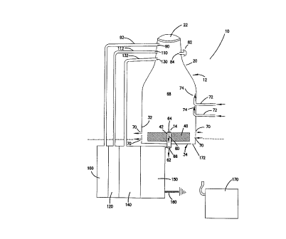
Fig. l is a side cross-sectional ~iew of a high-
~requency fan ventilator according to the invention
including additional aspects which may be included in
additional embodiments of the invention;
Fig. 2 is a lateral cross-sectional view of the
high-frequency fan ventilator according to an embodlment
of the present in~ention; and
Fig. 3 is a side cross-sectional view of the high-
frequency fan ventilator of Fi~. 1 showing the direction
of helical gas flow during the ro~ation of the fan
towards the rotating fan (explration) and away from ~he
fan (lnspiration~.
A~ NDEû S~EET
~3 -
CA 02224988 1997-12-03
DETAILE~ D~SC~I~TION OF TH~ I~EN~IOI~ , ',,; , ' :
In the following description of _~e pr~fe--èd ~-
embodLment, reference i~ made to the accompanying
drawings which form a part hereof, and in which is shown
by way of illu~tration the specific embodiment in which
the invention may be practiced. It is to be understood
that other embod~ments may be utilized a~ ~tructural
changes may be made without departing ~rom the scope of
the present in~ention.
The present invention pro~ides a high frequency fan
ventilator 1~ according to the present invention.
Oxygenation is improved by increases in either the
~raction of oxy~en in inspired gas (Fi~2) and/or ~y
increasing the mean airway pressure (P~) which is also
affected by the rate of gas flow entering the system
Increases in ~requency and/or ~entilation amplitude m~y
also improve oxygenati~n, but to a lesser extent.
Ventilation (carbon dioxide removal) is mainly
controlled ~y either the frequency o~ the fan's
rotation, the mean airway pre~sure, and/or the amplitude
o~ ~entilation waves (which is mainly determined by the
larger ~urface area of the fan's arms).
Re~erring to FIG. 1, the chamber lZ serves for gas
flow both in the direction to and away from the fan 14
The chamber's 12 qhape is tridimen~ional and may be
cyllndrical, rectangular box, conic or cubic. The
volume of the chamber 12 is pre~erably 500-15,000 ml.
A~E'.'IOEO S~EET
CA 02224988 l997-l2-03
WO 96~39216 PCT/lB96~007i2
The chamber 12 has a tapering or narrowing neck 20 which
is connected eventually to the patient's endotracheal
tube at connector or ventilation port 22. At the center
of the chamber's base 34, the rotating fan 14 is ~ixed.
The wall 32 of chamber 12 preferably has a thickness of
1-5 mm. The base 34 of the chamber 12 serves for
obstructing gas flow from the fan 14 in the direction of
the base 34 (contrary to regular ventilation fans in
rooms or offices), and has the rotating fan 14 fixed to
it.
The arms 40 of the fan 14 are connected to a fan
shaft 42. The shape of each arm 40 may be square,
rectangular, triangular or ellipsoid; but in the
preferred embodiment is rectangular. The angle between
the larger plane (length & width) of the fan's arm 40
and the chamber's base 34 iS preferably 90 degrees,
i.e., the planes formed by fan's arms 40 are
perpendicular to the chamber's base 34. However, this
angle can be varied. For example, angles between +3 5
and +150 degrees are effective but yet not as efficient~
In the preferred embodiment, each arm may be 2-50 cm in
length, 0. 5-20 cm wide, and 0. 5-10 mm thick. The
velocity of fan 14 is variable with 200-20,000 rpms
preferred. However, it is to be understood that this
velocity may be changed as needed.
The shaft 42 of the fan has a cylindrical or
rectangular box shape. Preferably the shaft 42 has an
internal radius of 2-15 mm, a height of 1-20 cm, and a
thickness of the wall of 1-5 mm. The shaft 42 has a
cylindrical or rectangular box lumen 60 through its
whole length. This lumen 60 connects the inside of the
chamber 12 to the atmosphere 62. This lumen 60 may be
open or closed as medically necessary. The internal
opening 64 of the fan's shaft 42 may be circular, square
or rectangular. Preferably the shaft internal opening
64 has a radius of 2-15 mm, and a thickness of the wall
of 1-5 mm. The external opening 66 of fan's shaft 42
could be circular, square or rectangular. Preferably,
CA 02224988 1997-12-03
W 096/39216 PCT~B96/00712
the external opening 66 of the fan's shaft 42 has a
radius of 2-15 mm, and a thickness of the wall of 1-5
mm.
The openings 70, through the container~s wall 32
serve for movement o:E gas from inside the chamber 12 to
outside the chamber 12. The openings 70 are preferably
located close to the fan's arms 40, but could be located
at any point on the walls 32 of the chamber 12.
Preferably, there are several openings 70 spaced about
the container 12, with each opening generally having a
width or diameter of 2-40 mm. Each opening 70 could be
intermittently closed or obstructed partially or fully
to serve as a pop-off valve, as a pneumatic valve, or as
a valve controlled by a microprocessor and a computer in
order to create and maintain a positive pressure of 0-40
cm H2O in the chamber 12 (and consequently in the
respiratory system) as pre-set clinically to sustain
lung inflation.
Internal paths 72 introduce the gas which is
enriched with pressurized air and or oxygen into the
chamber 12. The oxygen ports 74 and the internal paths
72 extend through the chamber's wall 32, preferably not
close to the fan's arms 40. Nevertheless, it is to be
understood that the oxygen ports 74 and internal paths
72 could be located at any point on the walls 32 of the
chamber 12. The paths 72 are shaped in such a way so
that the direction of entering gas is towards the
ventilation port 22 of the chamber 12, in opposition to
the direction of the fan 40 location.
Ventilation port 22 in chamber 12 connects the
chamber 12 to the patient's endotracheal ventilation
tube which leads to the patient~s lungs. The
ventilation port 22 may be circular and preferably has
an internal radius of 10-30 mm. Additional tubing may
be needed between the ventilation port 22 and the
patient's endotracheal tube.
Pop-off valve 82 functions as a safety valve. If
the pressure inside the chamber 12 exceeds a pre-set
CA 02224988 l997-l2-03
W096~9216 11 PCT~B96/00712
pressure of 20-80 cm H2O, then this valve 82 opens
immediately and releases extra pressure from the system
10. The internal opening 84 of the safety valve 82 is
located in the wall 32 of the chamber 12. The safety
valve opening 84 may be configured with a circular,
rectangular or square shape and preferably has a radius
or length of 2- 20 mm.
Temperature monitoring port 90 ~acilitates the
measurement and continuous monitoring of the temperature
inside the chamber 12. The temperature monitoring port
90 has a shape that is circular or sguare, and has a
radius or length of 2-15 mm. Furthermore, the
temperature monitoring port 90 is located in the wall 32
of chamber 12 close to the ventilation port.
Temperature monitoring tube 92 connects the temperature
monitoring port 90 to device 100 which continuously
measures, monitors and displays temperature of gas
inside the chamber 12. Preferably the temperature of
the gas inside the chamber 12 is maintained at 31-34~C.
Pressure monitoring port 110 is for measurement and
continuous monitoring of pressure inside the chamber 12.
The pressure monitoring port 110 has a shape that is
circular or square and has a radius or length of 2-15
mm. The pressure monitoring port 110 is also located in
the wall 32 of chamber 12 close to the ventilation port
22. Pressure monitoring tube 112 connects pressure
measurement port 110 to pressure monitor 120 which
continuously measures, monitors and displays pressure of
gas inside the container 12.
Humidity monitoring port 130 iS used for the
measurement and continuous monitoring of humidity inside
the chamber 12. The shape of the humidity monitoring
port 130 is circular or square and has a radius or
length of 2-15 mm. Preferably humidity monitoring port
130 is located in the wall 32 of chamber 12 close to
ventilation port 22. Humidity monitoring tube 132
connects humidity measurement port 130 to humidity
monitoring device 140 which continuously measures,
CA 02224988 l997-l2-03
W 096/39216 PCT~B96/00712
12
monitors and displays the humidity of the gas inside the
chamber 12 with the humidity preferably maintained at
40-100~ as pre-set clinically.
Fan rotator 150 rotates the fan 14. The fan
rotator 150 allows any velocity to be chosen in the
range of 200-20,000 rpm (rounds per minute). The fan
rotator 150, as well as monitoring devices 100, 120, 140
are connected to an electrical power source 160, and
controlled by a computer (not shown).
A water trap 170 may be implemented with the system
to drain extra water/fluid from the ventilation system
10. This water trap 170 may be connected either to the
lower side of the said ventilation chamber 12 via drain
172, to the lower side of the ventilation port 22 or to
the lower side of the additional tubing between the
chamber and the patient's endotracheal tube (not shown).
Fig. 2 is a lateral cross-sectional view of the
high-frequency fan ventilator 10. The fan 14 iS shown
disposed within the walls 32 of the chamber 12. The
shaft 42 of the fan 14 supports the arms 40 of the fan
14 and a lumen 60 through the shaft 42 connects the
inside of the chamber 12 to the atmosphere. This lumen
60 may be open or closed as medically indicated.
Temperature monitoring 92 connects the temperature
monitoring port to the temperature monitoring device
(not shown in Fig. 2). Pressure monitoring tube 112
connects pressure measurement port to pressure monitor
(not shown in Fig. 2). Humidity monitoring tube 132
connects humidity measurement port to humidity
monitoring device (not shown in Fig. 2).
Fig. 3 iS a side cross-sectional view of the high-
frequency fan ventilator 10 of the present invention
showing the direction of helical gas flow during the
rotation of the fan 14. Positive helical waves 200 in
the peripheral portion of the chamber 12 move away from
the fan 14 towards the ventilation port 22 for active
inspiration of gas to the lungs. Negative helical waves
210 move towards the center of the chamber 12 from the
CA 02224988 1997-12-03
W O 96~9216 PC~rnB~6~V~71Z
13
ventilation port 22 to the shaft 42 of the fan 14 for
active expiration of gas from the lungs.
In summary, a novel high-frequency ventilator and
method has been disclosed. Those skilled in the art
will recognize that the present invention may be
combined with other techniques known in the art such as
maintaining and monitoring of pressure, humidification,
and temperature inside the ventilation system, and
achieving better gas exchange between the patient's
lungs and the gas outside the patient and using less
pressure during ventilation, thus avoiding barotrauma to
airways and lungs, and the like.
The foregoing description of the preferred
embodiment of the invention has been presented for the
purposes of illustration and description. It is not
intended to be exhaustive or to limit the invention to
the precise form disclosed. Many modifications and
variations are possible in light of the above teaching.
It is intended that the scope of the invention be
limited not with this detailed description, but rather
by the claims appended hereto.